COMPUTATIONAL STUDY OF FLOW THROUGH A
SUPER HEATER FOR STUDY THE VARIOUS HEAT
TRANSFER CHARACTERISTICS
1
Prashant Kumkale,
2Dr.C.R.Sonawane
1PG Student,
2Associate Professor
Mechanical Engineering Department,
Pimpri Chinchwad College of Engineering, Pune, (India)
ABSTRACT
The super heater can be treated as the heart of any boiler system, the main duty of which is to supply desired
amount of steam regularly at rated temperature and pressure. In this paper internal flow analysis of a super
heater is done to study heat transfer characteristics of super heater of a boiler using a CFD (ANSYS-FLUENT)
package. The Computational Fluid Dynamics (CFD) approach utilized here to study many parameter such as
pressure drop, temperature, velocity, surface Nusselt number, Skin friction coefficient, total surface heat flux.
The mesh conversions study is helpful to choose the optimum mesh for the simulations.
Index Terms: CFD, Simulation.
I. INTRODUCTION
Super heater is mainly a heat exchanger in which heat is transferred from furnace gas to the steam. Due to
improper heat transfer between steam and furnace gas leads to problems of heating. Reduced performance,
repetitive failures in boiler components are common problems related to any type of boiler system. Super heater
tube failure is very common issue in boilers.In this investigation worked on CFD analysis of super heater flow
to study thermal parameters of super heater.
Tube failure in the super heater is hazardous enough to shut down whole plant hence it is important to take
remedial actions to avoid technical as well as economic losses. Proper distribution of furnace gas over entire
super heater tubes and uniform steam flow in each tube is suggested for trouble free operation of super heater.
Uneven heat transfer is a result of non-uniform gas flow or non-uniform steam distribution in super heater that is
because of scale formation on super heater wall. The significant causes of failure in super heaters are localized
prolonged heating, creep damage, thermal fatigue, excessive thermal stresses, water and erosion etc. The various
inspection techniques which, if used as part of a routine inspection program, are capable of identifying
conditions likely to result in failures[5]. It is evident the difficulty and need to solve such problems and even
identify critical regions that may be monitored by installing high temperature sensors, in order to reduce the
International Journal of Advance Research In Science And Engineering http://www.ijarse.com
IJARSE, Vol. No.3, Issue No.9, September 2014 ISSN-2319-8354(E)
system, the main duty of which is to supply desired amount of steam regularly at rated temperature and
pressure.CFD Technology is the tool which is used in boiler super heater tube to analyze the flow distribution of
steam along the tube and identify the critical zone, or maximum temperature regions in the super heater coil also
help to study the velocity and pressure distribution inside the super heater coils. Hence CFD model of super
heater may be utilized to study the velocity, pressure and temperature distribution, surface nusselt number, skin
friction coefficient, turbulence developed in the super heater of a boiler. Thus this study is focused on simulating
turbulent flow within the boiler super heater.
II. MESH CONVERSIONS STUDY
Geometry is drawn in CATIA V5 and step file of geometry is transfer to the Ansys Fluent 14.0 to mesh the
super heater geometry. There are 10 numbers of turns to the super heater of a pipe, geometry divide in 19 parts.
We are simulating only flow inside the super heater pipe, so that geometry material is fluid. The
preprocessor-software Ansys is used to generate the grids. Fig. 4.5 shows typical surface grids. Automatic meshing is done
for super heater pipe geometry so that results obtained are accurate so fine meshing is done and meshed
geometry is shown in fig 4.5.
The numerical simulations in this study have been performed based on some assumptions which were also the
assumptions of other researchers while studying the super heater flow analysis. Following are some of the
assumptions on which the current study is based.
The fluid is assumed to be incompressible with constant thermal physical properties and the flow is
assumed to be three dimensional, turbulent, steady and non-rotating. The working fluid is steam.
A constant temperature is prescribed on the super heater tube wall. No-slip velocity conditions are applied at all walls.
A uniform mass flow rate and temperature are set at the inlet. A pressure outlet condition is assumed at the outlet.
Fig.2 Meshed Geometry of Super Heater
Here geometry is divided in 19 parts to study the various thermal parameters in the different parts of the super
heater pipe as shown in the figure, the fluid flow from inlet to the outlet. Here line is drawn the inside the super
heater geometry at the center and measure the temperature and pressure at the various parts in the super heater
pipe, measure the pressure, temperature and drawn the curves for the section ST.
II. BOUNDARY CONDITIONS
Although the heat transfer in the super heater is important for boiler design, the heat transfer enhancement in the
boiler is the major concern of this project. A temperature is prescribed on wall. no-slip conditions are applied at
all walls. A uniform mass flow rate and temperature are set at the inlet and pressure outlet condition is chosen at
the outlet. The fluid is assumed to be incompressible with constant thermal physical properties and the flow is
assumed to be three dimensional, turbulent, steady and non-rotating. The working fluid is steam. In this study,
because of high Reynolds numbers and the complicated computational model, the standard wall functions of the
k- model are applied on the walls for the near wall treatment. The convergence criterion for continuity,
momentum, k, energy equation equations is 1e-6.
Flow is considered to be steady
Water Vapor is considered as the fluid for computations
Flow considered as Turbulent ( K-ϵ model)
Inlet considered as mass flow rate of magnitude 19.44 Kg/s for 45 pipes
Steam inlet temperature of fluid in 573 0 K
Outlet considered as pressure outlet of magnitude 40 kg/cm2
Steam density 18.46 kg/m3 at 43 kg/cm2 pressure and 573 0 K temperature
Dynamic viscosity of fluid 1.985e-5 kg/m-s
International Journal of Advance Research In Science And Engineering http://www.ijarse.com
IJARSE, Vol. No.3, Issue No.9, September 2014 ISSN-2319-8354(E)
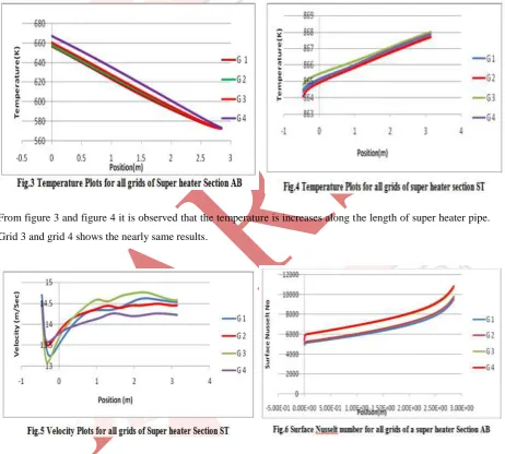
III. VARIOUS PLOTS FOR ALL GRIDS
To ensure the accuracy and validity of the numerical results, a careful check of the grid dependence of the
numerical solutions has been carried out by considering four grid systems with large number of grid points,
i.e.64932cells, 63900 cells, 50048 cells and 42080 cells for the simulations. The temperature, pressure at the
center line of the super heater geometry and surface nusselt number and skin friction coefficient for the wall of
the super heater from these four grid systems is plotted.
From figure 3 and figure 4 it is observed that the temperature is increases along the length of super heater pipe.
Grid 3 and grid 4 shows the nearly same results.
Figure 5 shows that the velocity is changed at the bending portion of the super heater, if a fluid is moving along
a straight pipe that after some point becomes curved, the bend will cause the fluid particles to change their main
From the figure 6 and figure 7 shows that the surface nusselt number is decreases along the length of the super
International Journal of Advance Research In Science And Engineering http://www.ijarse.com
IJARSE, Vol. No.3, Issue No.9, September 2014 ISSN-2319-8354(E)
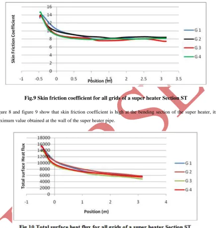
Fig.9 Skin friction coefficient for all grids of a super heater Section ST
Figure 8 and figure 9 show that skin friction coefficient is high at the bending section of the super heater, its
maximum value obtained at the wall of the super heater pipe.
Total surface heat flux is decreases along the length of super heater its magnitude is minimum at section ST of
super heater wall. The velocity is plotted at the centre line of the super heater section ST from this graph it is
observed that the velocity is increased along the length of the super heater then slightly decreased. Velocity is
high at bending section of super heater pipe. Skin friction coefficient is plotted along the super heater wall at the
section ST from this graph it is observed that skin friction coefficient decreases along the length at the last
section ST. Surface nusselt number is plotted along the super heater wall at the section ST from this graph it is
total surface heat flux and skin friction coefficient between 50048 cells and 63900 cells, 42080(i.e. Grid 2, Grid
3 and Grid 4) .Thus, to save computer resources and keeping a balance between computational economy and
prediction accuracy, the grid with 50048 cells is optimum mesh for the simulations.
III. CONCLUSION
From above results and study it is concluded that
1. Velocity is high at bending section of super heater pipe and pressure also decreases at same point.
2. Skin friction coefficient decreases along the length at the last section ST.
3. As the steam flowing inside the super heater tube the temperature of steam increases from inlet to outlet of
super heater.
4. Surface Nusselt number decreases along the length of super heater at the last section ST.
5. It is found that the normal deviation of temperature and pressure, surface Nusselt number, total surface heat
flux and skin friction coefficient between 50048 cells and 63900 cells, 42080(i.e. Grid 2, Grid 3 and Grid 4) .
Thus, to save computer resources and keeping a balance between computational economy and prediction
accuracy, the grid with 50048 cells is chosen for the simulations.
IV. ACKNOWLEDGMENT
It gives me great pleasure to express my deep gratitude to my project guide Dr. C. R.Sonawane for his support
and help from time to time during this work. It is my pleasure to acknowledge deep sense of gratitude to Mr.
Nagesh Bhujbal chief Engineer Shrinath Mhaskoba Sakhar Karkhana Ltd. for their great support.
REFERENCES
[1] Raja Saripalli, “Simulation Of Combustion And Thermal Flow in an Industrial Boiler” , ESLIE-05-05-42
, Proceedings of the Twenty-Seventh Industrial Energy Technology Conference, New Orleans, LA, May
10-13, 2005
[2] RahimiMasoud, Abbas Khoshhal and Syed Mehdi Shariati, (2006) CFD modeling of boiler tubes rupture.
Journal of Applied Thermal Engineering, 26, 2192-2200.
[3] J.S. Jayakumar , “CFD analysis of single-phase flows inside helically coiled tubes ” Elsevier Ltd.,
Computers and Chemical Engineering 34 (2010) 430–446 February 2009.
[4] Ajay N. Ingale,“CFD Analysis of Super heater in View of Boiler Tube Leakage”, International Journal of
Engineering and Innovative Technology (IJEIT) Volume 1, March 2012 ISSN: 2277-3754.
[5] ShajikumarK.R , “An Investigation on Tube Temperature Distribution in a Water Tube Boiler” IOSR
Journal of Mechanical and Civil Engineering (IOSRJMCE) ISSN: 2278-1684 Volume 2 (Sep-Oct. 2012),
pp 45-50.
[6] Shahida Begum, “Analysis of End Crack in Boiler Tube’’ Advanced Materials Research Vol. 576 (2012)
pp 749-752.
International Journal of Advance Research In Science And Engineering http://www.ijarse.com
IJARSE, Vol. No.3, Issue No.9, September 2014 ISSN-2319-8354(E)
[8] Raquel Antunes Hess, “Analysis of Heat Transfer and overheating failures associated with wall
temperatures in Steam Superheaters”,22nd International Congress of Mechanical Engineering (COBEM
2013) pp 3-7.
[9] Amit N Parit ,Tadamalle A. P. and Mrs. V. Ramaswamy “Failure Investigation of Secondary Super
Heater using CFD/CAE Technique”,IJERT Vol. 2 October – 2013 ISSN: 2278-0181.
[10] Prashant M Khanorkar , “Cfd Analysis of Natural Convection FlowThrough Vertical Pipe” Int. J. Mech.
Eng. & Rob. Res. 2013 ISSN 2278 – 0149 ,vol. 2, No. 3.
[11] Raja Saripally, Ting Wang and Benjamin Day. (2005) Simulation of combustion and thermal flow in an
industrial boiler, Proceedings of 27th Industrial Energy Technology Conference, New Orleans, Louisiana.
[12] Rahmani, “Assessment of boiler tubes overheating mechanisms during a postulated loss of feedwater
accident”, Applied Thermal Engineering 29 (2009) 501–508.
[13] Dr T C Mohankumar, “CFD Studies on Multi Lead Rifled [MLR] Boiler Tubes”, Nice Thomachan et al.
Int. Journal of Engineering Research and Applications ,Vol. 3, Sep-Oct 2013, pp.24-26
[14] AtulShivakarTambi ,“Numerical Analysis Of Solid Phase In A Circulating Fluidized Bed Boiler” ,
S.R.M. Engineering College, Kattankulathur Anna University: Chennai 600 025 May 2006.
[15] Qaiser Abbas, “Numerical Simulation and Experimental Verification of Air Flow through a Heated
Pipe”, International Journal of Mechanical & Mechatronics Engineering, IJMME-IJENS April 2010
vol:10 No:02.
[16] Hardeep Singh, “Thermal-Structural analysis of High Pressure Super heater 1 of a Heat Recovery Steam
Generator”, Arizona State University August 2012.
[17] Nicholas J. Mulvany, “Steady-State Evaluation of ’Two-Equation’ RANS (Reynolds-averaged
Navier-Stokes) Turbulence Models for High-Reynolds Number Hydrodynamic Flow Simulations .” ,DSTO
Platform Sciences Laboratory 506 Lorimer St. FishermansBend,Victoria 3207 Australia.
[18] Louise K.C. Axelsson , “Modelling Heat Transfer in the Cooling Pass of a Refuse-Fired Fluidised Bed
Combustor” Louise K.C. Axelsson, 2012. Technical Report No.T2012-381.
[19] Khoshhal , “CFD investigation on the effect of air temperature on air blowing cooling system for
preventing tube rupture” , International Communications in Heat and Mass Transfer 36 (2009) 750–756.
[20] Ang Wei Bing, “Development Of Iterative Analytical Procedure For Boiler Tube Analysis In Matlab” ,
UniversitiTunku Abdul Rahman,April 2013.
[21] Anna Lundborg KTH, “Simulation of the flue gas flow through the superheater in a recovery boiler ”
Sodahuskommittén 2006.
[22] J. P. Hollman, “Heat Transfer”, McGraw-Hill, New York, 1985.