On The Standardization of Ultra-High-Definition
(UHD) Video Transmission by Digital Video
Broadcasting – Satellite Second Generation (DVB-S2)
Urvashi Pal
B.Tech in Electronics and Telecommunications Engineering MSc in Mobile and Satellite Communication
COLLEGE OF ENGINEERING AND SCIENCE
VICTORIA UNIVERSITY
SUBMITTED IN FULFILLMENT OF THE REQUIREMENTS OF THE DEGREE OF
DOCTOR OF PHILOSOPHY
ii
©
Copyright by Urvashi Pal 2016
iv
Doctor of Philosophy Declaration
“I, Urvashi Pal, declare that the PhD thesis entitled ‘On The
Standardization of Ultra-High-Definition (UHD) Video Transmission by
Digital Video Broadcasting – Satellite Second Generation (DVB-S2)’ is no
more than 100,000 words in length including quotes and exclusive of
tables, figures, appendices, bibliography, references and footnotes. This
thesis contains no material that has been submitted previously, in whole or
in part, for the award of any other academic degree or diploma. Except
where otherwise indicated, this thesis is my own work”.
vi
ABSTRACT
Currently, the best quality video that can be viewed on our TV is at a resolution of 1920 x 1080 pixels, standardized as High-definition (HD). To view a video even bigger and better than HD, a new resolution has recently been standardized as Ultra-High-Definition (UHD) at a resolution of 3840 x 2160 pixels. However, to broadcast a UHD video using the standard broadcast method, Digital Video Broadcasting (DVB), an exclusive DVB-UHD broadcast profile is being developed, which defines parameters for the content being transmitted, the transmitter-receiver equipment, and the television displays. At present, we only have a broadcast profile for Standard-Definition (SD) and HD. Thus, the objective of this research work is to contribute towards the standardization of the DVB-UHD broadcast profile.
vii
Channel estimation is also performed on the received bits with the help of known pilot bits to reduce the noise.
viii
Acknowledgements
This thesis would not be complete without support and guidance from those to whom I deliver these acknowledgements.
I express my greatest gratitude to Dr. Horace King for the amazing supervisory process and his incredible patience in dealing with my research work, his ideas, guidance and knowledge support over the years.
I am also deeply grateful to Prof Mike Faulkner for his feedback that meant forcing my progress with great improvement.
I would like to thank John Hill, Senior Engineer-Broadcast Systems from Seven Network, to get in touch with Dr. Horace King regarding my research work and inviting us and Mike, to Mt. Dandenong and Docklands office for an extensive discussion on the current trends in broadcasting and UHDTV.
My great appreciation goes to Victoria University for providing me the VUIPRS Scholarship and tuition fees waiver for the duration of my PhD, without which my dream and journey of doing a PhD would not be complete. I would also like to express my gratitude to the Postgraduate Research and the Student Advice Officers, particularly Liz Smith and Lesley Birch, for always being there to assist me.
ix
Contents
Doctor of Philosophy Declaration...iv
Abstract...vi
Acknowledgements...viii
Contents...ix
List of Figures...xiv
List of Tables...xviii
List of Abbreviations...xix
1 Introduction...1
1.1 Background...1
1.2 Problem Statement...2
1.3 Scope...5
1.4 Research Objective and Contribution ...8
1.5 List of Publications...12
1.6 Thesis Organization...13
2 Literature Review of UHD Ecosystem...15
2.1 Introduction...15
2.2 Video Production...15
2.2.1 4K Resolution...15
2.2.2 High Frame Rates (HFR)...16
2.2.3 Wide Colour Gamut (WCG)...17
x
2.3 Video Compression: MPEG-4 vs. HEVC...19
2.3.1 Advantages of HEVC compared to MPEG-4...19
2.3.2 Disadvantages of HEVC compared to MPEG-4...19
2.4 Video Broadcasting...22
2.4.1 Using DVB-S2/S2X...22
2.4.2 Using Other Methods...23
2.4.2.1 DVB-T2/T2-Lite...23
2.4.2.2 IPTV: HbbTV and MPEG-DASH...24
2.5 Video Delivery Mechanisms...26
2.5.1 DVB-S2 UHD Satellites...26
2.5.2 SDI Cable and STBs...26
2.5.3 HDMI...27
2.6 Display and Backlight Technology...28
2.7 UHD Roadmap...29
2.8 Summary...30
3 Performance Analysis of DVB-S2...31
3.1 Introduction...31
3.2 Transmitter...33
3.2.1 Modulator Selection...33
3.2.1.1 QPSK Modulator...33
3.2.1.2 8PSK Modulator...34
xi
3.2.1.4 32APSK Modulator...35
3.3 Analysis of The Transmission Channel...37
3.3.1 Rician Fading Channel...37
3.3.2 Phase Noise...40
3.3.3 AWGN Channel...41
3.3.4 Error Correction Due to Channel Anomalies...43
3.3.4.1 Tanner Graph...43
3.3.4.2 Iterative LDPC Decoding...44
3.4 Summary...45
4 Analysis of UHD Video Broadcasting by DVB-S2...46
4.1 Introduction...46
4.2 Problems in DVB-S2...46
4.3 Importance of BER vs. SNR Calculation...47
4.3.1 Noise Channel...48
4.3.2 MOD-COD...48
4.3.3 Type of Video...48
4.4 Proposed Error Reduction Method: Channel Estimation...49
4.5 Effect of Symbol Rate on BER...50
4.6 Summary...54
5 Proposed Video Performance Evaluation Methodology...55
5.1 Introduction...55
xii
5.3 Video Quality Assessment...59
5.4 Video Performance Assessment: System Model...61
5.5 Experiment 1: In the presence of AWGN only...65
5.5.1 Result Summary - 1...65
5.6 Experiment 2: High Frame Rate Videos...68
5.6.1 Result Summary - 1...68
5.6.2 Result Summary - 2...69
5.6.3 Result Summary - 3...70
5.7 Experiment 3: Rician Fading and Channel Estimation...71
5.7.1 Channel Estimation Results Comparison...77
5.7.2 HD and UHD Results Comparison...77
5.7.3 Effect of Code Rate...78
5.7.4 Effect of Modulation Scheme...80
5.8 Summary...81
6 Proposed Modeling Using Experimental Results...82
6.1 Introduction...82
6.2 Correlation of Channel Capacity and Results from Exp. 3...82
6.3 Spectral Efficiency...83
6.4 Coverage Area: Distance Between Transmitter and Receiver...85
6.4.1 Distance between Transmitter and Receiver vs. BER...86
6.4.2 Distance between Transmitter and Receiver vs. Efficiency...87
xiii
6.5.1 Separation Distance vs. BER...90
6.5.2 Separation Distance vs. Efficiency...91
6.6 Formulating and Applying the Principle of Inclusion...92
6.7 Cost Increase due to UHD Video Broadcasting...96
6.8 Summary...100
7 Conclusion and Future Work...101
7.1 Summary...101
7.2 Conclusion...103
7.3 Further Work...104
xiv
List of Figures
1.1 HD (Left) vs. UHD (Right)...3
1.2 Co-existence of multiple video standards...4
2.1 HD and UHD Colour Space...18
2.2 HEVC Compression Technique...21
2.3 Comparison of MPEG-4/H.264 and HEVC/H.265 Compression...21
2.4 DVB-T2 System Architecture...24
2.5 Hybrid Television System Architecture...25
2.6 UHD development stages till now...29
2.7 UHD future roadmap...30
3.1 Direct-To-Home Pay-TV system model...32
3.2 DVB-S2 block schematic...32
3.3 Constellation Diagram of QPSK (left) and 8PSK (right)...34
3.4 Constellation Diagram of 16APSK and 32APSK...36
3.5 Tanner Graph...44
4.1 Channel Estimation Block Schematic...50
4.2 One symbol in a Nyquist Filter...53
5.1 HD video frames used for experiment...56
5.2 UHD video frames used for experiment...56
5.3 Future broadcast scenario...57
5.4 Colour range of HEVC HD 1080/25p video...60
xv
5.6 Colour range of HEVC UHD 1080/25p video...60
5.7 Colour range of HEVC UHD 2160/25p video...60
5.8 MPEG-TS BBFRAME...61
5.9 BER vs. SNR of UHD and HD for QPSK-3/4, with AWGN...66
5.10 BER vs. SNR of UHD and HD for 8PSK-3/4, with AWGN...66
5.11 BER vs. SNR of UHD and HD for QPSK-5/6, with AWGN...66
5.12 BER vs. SNR of UHD and HD for 8PSK-5/6, with AWGN...66
5.13 BER vs. SNR of UHD and HD for QPSK-9/10, with AWGN...66
5.14 BER vs. SNR of UHD and HD for 8PSK-9/10, with AWGN...66
5.15 BER vs. SNR of UHD and HD for 16APSK-3/4, with AWGN...67
5.16 BER vs. SNR of UHD and HD for 32APSK-3/4, with AWGN...67
5.17 BER vs. SNR of UHD and HD for 16APSK-5/6, with AWGN...67
5.18 BER vs. SNR of UHD and HD for 32APSK-5/6, with AWGN...67
5.19 BER vs. SNR of UHD and HD for 16APSK-9/10, with AWGN...67
5.20 BER vs. SNR of UHD and HD for 32APSK-9/10, with AWGN...67
5.21 Understanding HFRs...69
5.22 Signal performance of different video standards, when transmitted through 8PSK-5/6 in the presence of AWGN...70
5.23 Constellation diagrams of different modulation schemes with noise, at SNR=20dB for Rician Fading Channel (K=5)...72
5.24 BER vs. SNR for QPSK-3/4 (a) Rayleigh Fading (b) Rician Fading...73
xvi
5.26 BER vs. SNR for QPSK-9/10 (a) Rayleigh Fading (b) Rician Fading...73
5.27 BER vs. SNR for 8PSK-3/4 (a) Rayleigh Fading (b) Rician Fading...74
5.28 BER vs. SNR for 8PSK-5/6 (a) Rayleigh Fading (b) Rician Fading...74
5.29 BER vs. SNR for 8PSK-9/10 (a) Rayleigh Fading (b) Rician Fading...74
5.30 BER vs. SNR for 16APSK-3/4 (a) Rayleigh Fading (b) Rician Fading...75
5.31 BER vs. SNR for 16APSK-5/6 (a) Rayleigh Fading (b) Rician Fading...75
5.32 BER vs. SNR for 16APSK-9/10 (a) Rayleigh Fading (b) Rician Fading...75
5.33 BER vs. SNR for 32APSK-3/4 (a) Rayleigh Fading (b) Rician Fading...76
5.34 BER vs. SNR for 32APSK-5/6 (a) Rayleigh Fading (b) Rician Fading...76
5.35 BER vs. SNR for 32APSK-9/10 (a) Rayleigh Fading (b) Rician Fading...76
5.36 Combined results of Channel Estimation...77
5.37 Channel Estimation results: UHD (black) vs. HD (red)...78
5.38 Comparison of modulation schemes for different code rates...79
5.39 Comparison of code rates for different modulation schemes...80
6.1 Capacity vs. BER graph for Rayleigh and Rician Fading Channel...83
6.2 Capacity vs. Efficiency graph...84
6.3 Distance between transmitter and receiver vs. BER for Rayleigh and Rician....86
6.4 Distance between Transmitter and Receiver vs. Modulation Efficiency graph..87
6.5 Hexagonal packing of co-channel traditional broadcasters...89
6.6 Separation distance vs. BER graph for Rayleigh and Rician...90
xvii
6.8 MODCOD scheme affecting the transmitter coverage area (approx.
depiction)...91
6.9 UHD Transmit Power...97
6.10 UHD Receive Power...98
xviii
List of Tables
1.1 Contribution Towards Modulation and Coding Scheme...9
1.2 Contribution Towards Resolution...10
1.3 Contribution Towards Frame Rate...10
1.4 Contribution Towards Video Compression...11
2.1 Code rates comparison between DVB-S2 and DVB-S2X...23
2.2 Comparison of Different Broadcast Models...25
2.3 Technical parameters for satellite reception of a UHD channel...26
2.4 SMPTE SDI cables supporting PAL videos...26
2.5 HDMI 1.4a vs. HDMI 2.0...27
2.6 List of some companies working towards UHD...29
3.1 Optimum Constellation Radius Ratio for 16APSK...35
3.2 Optimum Constellation Radius Ratios for 32APSK...36
5.1 Description of formation of multiple video standards...58
5.2 Coding Parameters for FEC Block Size = 64800...61
6.1 Modulation Efficiency for different MODCOD schemes...84
xix
List of Abbreviations
ACM Adaptive Coding and Modulation APSK Amplitude Phase Shift Keying AVC Adaptive Video Coding
BCH Bose, Chaudhuri, and Hocquenghem BER Bit Error Rate
BSS Broadcast Satellite Services
CB Coding block
CCFL Cold-Cathode Fluorescent Lamps
CI Common Interface
CTB Coding Tree Block CTU Coding Tree Unit
DASH Dynamic Adaptive Streaming Over HTTP DSNG Digital Satellite News Gathering
DTH Direct-To-Home
DVB-S2 Digital Video Broadcast-Satellite Second Generation
DVB-S2X Digital Video Broadcast-Satellite Second Generation Extension EBU European Broadcasting Union
xx FSS Fixed Satellite Services
HbbTV Hybrid Television
HD High Definition
HDMI High Definition Motion Interface HDR Higher Dynamic Range
HEVC High Efficiency Video Coding HFR Higher Frame Rate
IPTV Internet Protocol Television
ITU International Telecommunication Union LCD Liquid Crystal Display
LDPC Low Density Parity Check LED Light Emitting Diodes
MPEG-4 Moving Pictures Expert Group
OFDM Orthogonal Frequency Division Multiplexing OLED Organic Light-Emitting Diode
PB Prediction block PLP Physical Layer Pipe PSK Phase Shift Keying
QPSK Quadrature Phase Shift Keying
RS Reed-Solomon coding
xxi SFN Single Frequency Network
SMPTE Society of Motion Picture & Television Engineers SNR Signal to Noise Ratio
STB Set Top Box
SVC Scalable Video Coding
TB Transform Block
TCM Trellis Coded Modulation TFT Thin Film Transistors
TS Transport Stream
UHD Ultra High Definition
1
Chapter 1
Introduction
1.1 Background
In the past the only video format available to view programs or movies on our television screen, was at a resolution of 720 x 576 pixels, known as Standard Definition (SD). This was followed by High-Definition (HD) video resolution of 1920 x 1080 pixels, which had a better picture quality and bigger size than SD, but consumed more bandwidth. In 2013, the International Telecommunication Union (ITU), standardized a new digital video format known as Ultra-High Definition (UHD), having two resolutions [1]:
• 3840 x 2160 pixels: UHD-1 or 4K • 7680 x 4320 pixels: UHD-2 or 8K
2
for HD and SD. Since 2013, European Broadcasting Union (EBU) has been working with partners such as DVB, ITU and the Society of Motion Picture and Television Engineers (SMPTE) to enhance the best UHDTV production and distribution technologies [3], and migration strategies, from HD to UHD (by 2017 for UHD-1 and by 2020 for UHD-2) [4]. Thus, the objective of this research work is to contribute towards the standardization of a UHD broadcast profile, to be defined by DVB in the coming years.
1.2 Problem statement
“Will UHD perform differently to HD over the air? Will it be more susceptible to noise? Will this result in a higher transmission power cost? Does High Frame Rate (HFR) require more bandwidth?
Will upscaling or downscaling solve all these problems?”
3
Figure 1.1: HD (Left) vs. UHD (Right) [7]
4
Figure 1.2: Co-existence of multiple video standards [10][11]
5
standards and since, a digital wireless communication is prone to noise or bit errors, it is crucial to study the end-to-end signal performance of different video standards being transmitted over-the-air. Bit Error Rate (BER) v/s Signal to Noise Ratio (SNR) simulations provides an ideal way to determine the effects on the quality of signal transmission [15].
While research work on UHD video quality assessment like Peak-SNR (PSNR) calculation has been carried out and, subjective and objective assessments have become quite common [16], there are very few research papers calculating the effect of noise on UHD and HD videos with varying parameters, in a wireless transmission. The video quality assessment is done mostly at the production level before video transmission is done. Once the signal is transmitted over air, the video quality is bound to deteriorate and hence, the study of noise channels on different types of videos is equally important. Unlike many other forms of analysis, BER v/s SNR determines the full end-to-end performance of a system at the given signal power, including the transmitter, receiver and the medium between the two. By calculating BER, the bit errors caused by disturbance on the transmission path can be corrected by using error correction methods at the receiver [17].
1.3 Scope
In this research project,
• Signal performance (BER v/s SNR) of a UHD video transmission by DVB-S2,
6
interferences, for different modulation and coding schemes.
• Interference experienced by the transmitted video signal, in a wireless
communication channel of DVB-S2, deteriorates the signal quality and thus, a method to improve the signal recovery is also proposed.
The impact of signal performance is observed for the following:
• Shannon Channel Capacity • Spectral Efficiency
• Coverage area: Distance between Transmitter and Receiver • Service Area Separation Distance
• An adaptive video quality system using the proposed and developed
Principle of Inclusion
• Transmission Cost
7
and users have to rely on expensive television sets to artificially generate frames by software algorithms, which will still have inevitable artifacts [19]. This quality cannot be assumed to be equivalent to an original video of 50fps in progressive mode. Similarly, it is most likely for broadcasters to transmit UHD content using MPEG-4 (recommended for HD) video compression, instead of HEVC (latest video compression format, recommended for UHD), and at 1080p resolution, instead of 2160p. Some might just upscale the HD video to view them on UHDTV due to the lack of content or downscale UHD videos to view them on HDTV due to the lack of infrastructure [20].
This dilemma of broadcasters and consumers has prevented the complete roll-out of the real HDTV till now, and the same reason might prevent the complete roll-out of the real UHDTV. Therefore, it is entirely the broadcaster’s decision, which video compression and MODCOD (modulation-coding) scheme will be adopted for transmitting a UHD video. There is a trade off between quality and cost in every option, and this research will explore every aspect of these scenarios from which the broadcasters can take an optimum decision towards their future planning of a UHD-DVB broadcast profile [4][5]. Other than movies and TV programs, UHD video broadcast will be useful in other applications where minute pixel data plays an important role [21], applications include the following:
• Medical imaging
• Weather forecasting
• Disaster Recovery
8
1.4 Research Objective and Contribution
The objective of this research work is to define the requirement of a UHD broadcast profile and contribute towards its standardization [22]. The investigation will help members of EBU, SMPTE, DVB and ITU-R, to make strategic decisions for future production and distribution technologies, by identifying the market demand per service type, commercial requirements and the backward compatibility of the UHD content with HDTV applications.
At the moment, many of the technical aspects of UHD broadcasting are yet to be agreed upon at a global level. To make UHD broadcasting a reality, we need a complete ecosystem, with content being made that the public wants, transmitters, receivers, and displays that are readily available. The specification should also consider features that the system would need to make it commercially successful. Some DVB Members think that displays for UHD-2 are too far away to be considered now, while others argue that UHD-2 is inevitable [23]. Therefore, we need to understand the requirements based on the trends of UHD-1 and when we can expect UHD-2 on the market. We also need to consider whether we can use DVB-S2 for UHD or not. Therefore, this research will analyze the performance of UHD video signals, with varying parameters as compared to HD, when transmitted by DVB-S2.
9
many consumers will buy an expensive television of 42ʹʹ and not every broadcaster will
have enough bandwidth, to air every channel in full resolution, thereby, resulting in non-ideal standard adoption. UHD has many parameters defining its video quality and the broadcaster needs to decide, which set of parameter they need to choose for a particular program and channel [24].
A news channel, where the anchor is mostly sitting in one place, talking to others, is a low bandwidth broadcasting requirement. While, a sports channel showing F1 race, where video graphics change every second, requires a higher frame rate and higher bandwidth. This thesis contributes towards a detailed study of the parameters in every combination of a UHD channel, which will help the broadcasters in the migration phase from HD to UHD, as explained in the following tables:
Table 1.1: Contribution Towards Modulation and Coding Scheme
What is known [25]
DVB-S2 Modulation and coding schemes
Fact [26] UHD content will be transmitted over the air, along with HD simulcasting. Hence, a detailed signal performance comparison between HD and UHD is required.
What is not known
Are UHD and HD videos going to perform similarly under every MODCOD scheme and Noise?
Thesis Contribution
Proposed experiments to determine whether:
1) UHD BER is higher or lower than HD in QPSK and 8PSK, 3/4 and 5/6 scheme, in the presence of AWGN
2) UHD BER is higher or lower than HD in QPSK and 16APSK, 3/4 and 5/6, in a Rician Fading Channel (K=5).
10
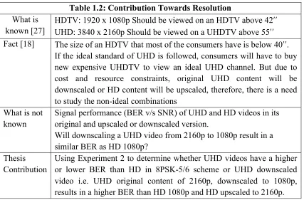
Table 1.2: Contribution Towards Resolution
What is known [27]
HDTV: 1920 x 1080p Should be viewed on an HDTV above 42ʹʹ
UHD: 3840 x 2160p Should be viewed on a UHDTV above 55ʹʹ
Fact [18] The size of an HDTV that most of the consumers have is below 40ʹʹ.
If the ideal standard of UHD is followed, consumers will have to buy new expensive UHDTV to view an ideal UHD channel. But due to cost and resource constraints, original UHD content will be downscaled or HD content will be upscaled, therefore, there is a need to study the non-ideal combinations
What is not known
Signal performance (BER v/s SNR) of UHD and HD videos in its original and upscaled or downscaled version.
Will downscaling a UHD video from 2160p to 1080p result in a similar BER as HD 1080p?
Thesis Contribution
Using Experiment 2 to determine whether UHD videos have a higher or lower BER than HD in 8PSK-5/6 scheme or UHD downscaled video i.e. UHD original content of 2160p, downscaled to 1080p, results in a higher BER than HD 1080p and HD upscaled to 2160p.
Table 1.3: Contribution Towards Frame Rate
What is known [28]
UHD: 25, 50, 100fps (only progressive) HD: 25 fps (progressive and interlaced) Facts
[29][30]
Lower frame rates should be used for movie channels. Higher frame rates should be used for sports channel. Interlaced videos save bandwidth and cost.
Wrong notion that HFR will result in an increased bandwidth and BER.
What is not known
Will HFR result in an increased BER or bandwidth? Will 1080p/50 HD video be the same as 2160p/25 UHD? Will upscaling and downscaling solve the problem? Thesis
Contribution
11
Table 1.4: Contribution Towards Video Compression
What is known [31][32]
MPEG-4: Currently being used for HD
HEVC: 50% more efficient than MPEG-4 and is to be used for UHD
Facts [33]
HEVC is still being improved and its compatible hardware is still not widely available. Therefore, in the initial UHD broadcast phase, MPEG-4 will be used for UHD compression.
If broadcasters use HEVC for UHD video compression, consumers cannot view UHD on their HDTVs.
If broadcasters use MPEG-4, it will consume high bandwidth as one UHD channel will consume the bandwidth of four HD channels. What is not
known
Will MPEG-4 and HEVC compressed video, result in the same BER?
Thesis Contribution
12
1.5 List of Publications
A number of peer-reviewed publications have been generated from the research accomplished in this thesis.
• 1) Horace King, Urvashi Pal, “A Statistical Approach to Determine Handover
Success Using the Principle of Inclusion and Load Variation on Links in Wireless Networks”, International Journal of Information, Communication Technology and Applications (IJICTA), Vol. 1, No. 1 (2015), pp. 143-151, December 2015.
• 2) Urvashi Pal, Horace King, “Bit Error Rate (BER) analysis of UHD High
Frame Rate (HFR) videos through different modulation schemes”, International Broadcasting Convention (IBC) - 2015, Future Zone, RAI Amsterdam, September 2015.
• 3) Urvashi Pal, Horace King, “Effect of Ultra High Definition (UHD) High
Frame Rates (HFR) on Video Transmission”, Society of Motion Pictures and Television Engineers, Sydney (SMPTE), Australia, July 2015.
• 4) Urvashi pal, Horace King, “Effect of Modulation Scheme on Ultra-High
Definition (UHD) Video Transmission”, accepted for IEEE Wireless Telecommunication symposium (WTS), New York City, USA, April 2015.
• 5) Urvashi Pal, Horace King, “DVB-S2 Channel Estimation and Decoding in
13
1.6 Thesis Organization
This research is devoted to the standardization of UHD video transmission by DVB-S2. Chapter 1 lays the foundation by analyzing the background literature, establish the problem statement and provide the research objectives and contributions.
Chapter 2 analyzes UHD ecosystem and discusses the features added to the UHD ecosystem such as 4K resolution, Higher Frame Rate, Wide Colour Gamut, Higher Dynamic Range and the new advanced and highly efficient video codec HEVC. It also discusses the different methods to broadcast this enormous video content. Further, it describes the infrastructure required for UHD delivery through DVB-S2. In addition. the latest television receivers available on the market today are discussed. The chapter is summarized by setting the UHD roadmap of the future.
Chapter 3 analyzes and explains Encoding-Modulation and Decoding-Demodulation in the DVB-S2 system. It also reviews effects on a signal in a wireless communication channel due to Rician Fading, correlated phase noise and AWGN.
Chapter 4 analyzes the scenario of UHD video broadcasting through DVB-S2. Since many organizations are working towards the standardization of DVB-UHD standard, the problem of BER in this scenario is explored. The Importance of BER vs. SNR calculation is explained and a method to reduce the error rate, known as Channel Estimation using pilot bits, is proposed.
14
experiments are performed. In Experiment 1, two videos (HEVC HD 1080p/25 and HEVC UHD 2160p/25) and transmitted through DVB-S2 model in the presence of AWGN for different modulation schemes and code rates (QPSK, 8PSK, 16APSK and 32APSK & 3/4, 5/6 and 9/10 rate). In Experiment 2, sixteen different videos varying in original content (HD, UHD) resolution (1080p, 2160p), frame rate (25fps, 50fps), codec (MPEG-4, HEVC) are transmitted through DVB-S2 model in the presence of AWGN only, for 8PSK-5/6 scheme. In Experiment 3, two videos of Experiment 1 are transmitted through DVB-S2 in the presence of Rayleigh Fading Channel (K=0) and Rician Fading Channel (K=5), correlated phase noise and AWGN. The same experiment is repeated after applying channel estimation method using pilot bits, to reduce the BER.
In Chapter 6, results of chapter 5 are used to calculate the Channel Capacity, Coverage area (Distance between Transmitter and Receiver), Service area Separation Distance. Using these parameters, the Principle of Inclusion is developed and implemented and, a UHD parameter adaptive scenario is explained. It is shown that there is an increase in the cost of transmission power to broadcast a UHD video, as compared to HD using the developed formulations.
15
Chapter 2
Literature Review of UHD Ecosystem
2.1 Introduction
“The colours are breathtaking. The clarity is flawless.
The definition is so sharp that viewers feel truly immersed in the action.” [19] With a wealth of benefits including four times higher resolution than HD, faster frame rate, higher dynamic range and a wider colour gamut, television and media industry is on the cusp of a revolutionary transformation in video transmission. UHD’s advanced technology promises to surpass consumer’s expectations. By region, its household penetration will reach 33% in North America, 22% in Western Europe and 18% in Asia Pacific by 2020 [19]. Hence, the following features have been introduced or modified to provide users with an ‘Ultra’-HD experience.
2.2 Video Production
2.2.1 4K Resolution
16
quality. The ideal size of a UHDTV is supposed to be around 55ʺ to 80ʺ. Based on the
size of television, viewing distance is calculated to maintain the maximum perceived angular resolution because there are limits to what an eye can perceive [34]. If you sit too close to the TV, you will be seeing the unwanted individual pixels and if you sit too far, you won't be able to observe all the details in the video. That means, if you sit too far away from a UHDTV, the UHD content will look like HD. As a result, the viewing distance for a UHDTV is half of what is required for HDTV.
2.2.2 High Frame Rates (HFR)
Ultra HD changes the way moving images are displayed, stored, and transmitted. To ensure a smooth viewing experience, HFRs will be used for UHD and HD videos in the future [2]. Until now, interlaced scanning (odd and even lines transmitted in turn) was being used to save bandwidth. However, there was a trade off with quality. Although, most recent HDTVs have the technology to de-interlace the frames, the artifacts could never be eliminated completely. Hence for UHD, the signal will mostly be transmitted in progressive mode, since it offers higher vertical resolution, better picture quality and easier frame conversion to other formats.
17
HFR technology was first introduced for 3D movies and has now been adopted for UHD videos [35]. “The Hobbit: An unexpected journey” (2012) in 3D, was the first movie to be shot at an HFR of 48fps (double of 24fps). Simultaneously, a new frame rate for HDTV at 50 fps (progressive) has also been standardized, keeping in mind that UHDTV will take time to penetrate the market and there is already a demand for increased video quality among the users [6]. DVB has included 1080p/50 format in its DVB specification TS 101 154 V1.9.1, for Advanced Video Coding (AVC) and Scalable Video Coding (SVC). Broadcasting in 1080/50p will be possible when new UHD STB arrive in the market (with HEVC encoding), offering progressive mode in the channels, not yet available.
2.2.3 Wide Colour Gamut (WCG)
18
improvement in display technology will enable the human eye to use more of its potential and foster viewing experience that will appear more and more lifelike [36].
Figure 2.1: HD and UHD Colour Space [37]
2.2.4 High Dynamic Range (HDR)
19
2.3 Video Compression: MPEG-4 vs. HEVC
At present, MPEG-4 video compression format is being used to watch HD channels on our HDTVs. HEVC is the new video compression method, developed especially to compress the huge data of UHD and has been adopted for its transmission by DVB [41].
2.3.1 Advantages of HEVC compared to MPEG-4 [42][43]:
• HEVC offers 50% higher video compression and quality as compared to MPEG-4
and therefore, will make the transmission of UHD content more efficient by saving the bandwidth significantly. Example: Using MPEG-4, 1 UHD channel will be available, and using HEVC, 4 UHD channels will be available using the same bandwidth.
• With the high performance of HEVC, about the same bit-rate used for 1080i/50
broadcast will be required for 1080p/50, and a better image quality will be delivered to the home. This is because compression avoids transmitting the entire frame whose information has already been transmitted in the previous frames. It only transmits the residual information between the referenced frame and current frame. Hence, the total bit rate is reduced and bandwidth is saved [15].
2.3.2 Disadvantages of HEVC compared to MPEG-4 [42][43]:
• HEVC encoder and decoder is at its early stage of development and not much has
been finalized yet.
• To use HEVC, broadcasters will have to invest in upgraded infrastructure, which
20
• If the broadcasters start using HEVC to transmit UHD, consumers will be forced to
dump their existing HDTVs and buy expensive HEVC compatible UHDTVs, and this will take time.
• UHD HEVC channels TV package will be costlier than what the consumer is paying
at present for HD MPEG-4 channels, hence, HEVC-UHD will take time to successfully hit the market.
Due to the disadvantages of HEVC, in the early migration phase of UHD the broadcasters will be left with no other choice, but to broadcast UHD channels in MPEG-4 format, compromising quality and bandwidth. HEVC was previously being developed for only-progressive mode, however, most of the producers and broadcasters still use the legacy interlaced format and cannot be abandoned at once and migrated to progressive format so soon; leading to HEVC introducing interlaced video compression. The introduction of new video formats (1080p/50, 2160p/ 25, 2160p/50) in addition to an existing one (720p or 1080i) may require simulcasting the same service at different formats. In such a scenario, the combination of MPEG-4 or AVC, SVC and HEVC will be used for different video formats [10][44].
HEVC Working:
HEVC video codec divides a frame into Coding Tree Units (CTU), which consist of Coding Tree Blocks (CTB) i.e. one Luma (Y), two Chroma samples (Cb, Cr) and
21
(8 x 8) pixels, by changing the size according to texture (MPEG-4 uses macro-block sizes maximum of (16 x 16) pixels). Different Prediction Blocks (PB) are introduced for precise prediction of the moving images. A Coding Block (CB) is further split into Transform Blocks (TB) to code the difference between the predicted image and the actual image. The complete process is explained in Figure 2.2. Figure 2.3 shows a comparison of HEVC and MPEG-4 compression technique [42].
Step 1:
CTU CTU CTU CTU CTU
CTU CTU CTU CTU CTU
CTU CTU CTU CTU CTU
CTU CTU CTU CTU CTU
Image Frame Divided into CTUs
Figure 2.2: HEVC Compression Technique [31]
22
2.4 Video Broadcasting
2.4.1 Using DVB-S2/S2X
DVB-S2 is the technique for Direct-to-Home (DTH) services. It uses Bose-Chaudhuri-Hocquenghem (BCH) + Low Density Parity Check (LDPC) encoder-decoder and interleaver (except for QPSK), combined with a variety of modulation schemes and code rates, along with Adaptive Coding Modulation (ACM), resulting in an improved efficiency of 30-35% as compared to DVB-S [46]. The adoption of new S2 Extension (S2X) will further improve the efficiency by 20% (for DTH) and 51% for other professional applications, by providing more speed, mobility and robustness. DVB-S2X target is to support the rising demand for higher quality images with the rise of UHDTV and HEVC [47].
23
(5%, 10% and 15%), wideband implementation, and additional scrambling sequences are added, resulting in an increased bandwidth [48].
Table 2.1: Code rates comparison between DVB-S2 and DVB-S2X [46][14]
DVB-S2 DVB-S2X
QPSK 1/2, 1/4, 1/3, 2/5, 3/5, 2/3,
3/4, 4/5, 5/6, 8/9, 9/10 13/45, 9/20, 11/20 8PSK 3/5, 2/3, 3/4, 5/6, 8/9, 9/10 23/36, 25/36, 13/18
16APSK 2/3, 3/4, 4/5, 5/6, 8/9, 9/10 26/45, 3/5, 28/45, 23/36,25/36, 13/18, 7/9, 77/90 32APSK 3/4, 4/5, 5/6, 8/9, 9/10 32/45, 11/15, 7/9
2.4.2 Using Other Methods
2.4.2.1
DVB-T2/T2-Lite
24
parameter set. However, the disadvantage of this technology is that it is not possible to broadcast throughout the year due to adverse weather conditions and the available bandwidth is also low, as compared to DVB-S2. DVB-T2 system model, given in Figure 2.4 [49].
Figure 2.4: DVB-T2 System Architecture [49]
2.4.2.2 IPTV: HbbTV and MPEG-DASH
25
behavior so that the user is not distracted during parameter change [53][54]. HbbTV is the hybrid of IPTV and DVB-S2, as shown in Figure 2.5 [55]. Its disadvantage is the lack of coverage in most regions on the globe; lower picture quality and available bandwidth as compared to DVB-S2 [10]. Therefore, DVB-S2 is the best possible broadcast method available, out of all the other methods. A comparison with other technologies is given in Table 2.2.
Figure 2.5: Hybrid television system architecture [55]
Table 2.2: Comparison of different broadcast models [10]
Method Coverage Picture Quality Calendar Bandwidth Availability
DVB-S2 Good Good Average Good
DVB-T2 Average Good Limited Limited
26
2.5 Video Delivery Mechanisms
2.5.1 DVB-S2 UHD Satellites
At the present time, UHDTV channels are being trialed and tested with the help of demo channels via S2 supported satellites, which are inline with the DVB-UHDTV phase-1 specifications [56]. Table 2.3. describes the technical parameters for satellite reception of a UHDTV channel by DVB-S2 satellites.
Table 2.3: Technical parameters for satellite reception of a UHD channel [57][58]
UHD Satellite Frequency (MHz) Modulation-Coding
Hot Bird 4K1, 13°East
Eutelsat 10A, 10°East
Eutelsat 10A, 10°East
SES Astra, 19.2°East
11296 11429 11346 10994 8PSK, 3/4 8PSK, 5/6 8PSK, 5/6 8PSK, 5/6
2.5.2 Serial Digital Interface (SDI) Cables and STBs
Table 2.4 enlists current and future SDI cables standardized for supporting UHDTV. Due to the high demand for UHD video standard, video equipment suppliers are already working on future technologies to support faster data rates.
Table 2.4: SMPTE SDI cables supporting PAL videos [14][15]
Cable Supported Video upto Data rate
SD-SDI HD-SDI 3G-SDI 6G-SDI 12-SDI 24-SDI 480i/25 270p/50, 1080i/50 1080p/50 2160p/25 (upcoming) 2160p/50 (unofficial) Next-gen tech (unofficial)
27
From Table 2.4, it is evident that future SDI cables take into account the increase in the number of pixels and frame rates and in concert with the increase in data rates into higher Gbps.
2.5.3 High Definition Multimedia Interface (HDMI)
HDMI 2.0 can transmit 12-bit per sample RGB at 2160p (progressive) and 24/25/30 fps or it can transmit 12-bits per sample 4:2:2/4:2:0 YCbCr at 2160p and 50/60
fps. UHDTVs released before HDMI 2.0, support the current HDMI 1.4 version, which limits UHD content to 24-30 fps [59]. Even after the launch of 6G-SDI cables, viewers will only be able to receive UHD channels on their television sets, if they have a compatible 4K STB supporting the latest HDMI 2.0 standard.
Till now, most of the TVs and STBs use HDMI 1.4a (6.05 Gbps usable bandwidth), which supports videos for 1080p/60 (1920 x 1080 resolution, 60 frames per second in progressive mode) and 2160p/30. However, to support 2160p/60 and other enhanced features of UHD video and audio, we need HDMI 2.0 (14.4 usable bandwidth out of 18 Gbps), This upgrade can either be a firmware update or a hardware update depending on different TV and STB manufacturers [60]. Table 2.5 highlights its features.
Table 2.5: HDMI 1.4a vs. HDMI 2.0 [59]
Format/
HDMI version 1080p/ 25fps 1080p/ 50fps 2160p/ 25fps 2160p/ 50fps 8-bit 10-bit 12-bit Sampling 4:4:4
1.4a Yes Yes Yes NO Yes NO NO
28
2.6 Display and Backlight Technology
The colour accuracy of a Liquid Crystal Display (LCD) TV screen depends on the backlight technology used to produce the white light. The various backlight technologies available today are:
Cold-Cathode Fluorescent Lamps (CCFL) is the old backlight technology that produces light strongest in greens and not exactly white and therefore, are not suitable for UHDTVs.
Light Emitting Diodes (LED) backlight with LCD display is the perfect choice for UHDTV as they produce whiter whites than CCFL since they use a non-coloured light source to illuminate the screen.
Quantum Dots (QD) is the same LED backlight technology for LCD display; however, the method to create colours is new. Quantum Dots directly convert light from blue LEDs into primary colours, rather than using the existing white LEDs. A QD emits light in a specific Gaussian distribution resulting in more accurate colours with improved brightness, that are not colour filtered and thus require low power.
Organic Light-Emitting Diode (OLED) display is an alternative to LCD Thin Film Transistor (TFT) display that offers higher brightness and contrast ratio since it is a light emitter and creates Lambertian light. It can be seen uniformly at all angles and gives a very pleasing effect. It does not require any backlight and can be made thinner (at 2mm) than LED (3mm). OLEDs are expensive and require a glass-covered screen.
29
eliminating the reflections from ambient lights sources. Curved displays are suitable for TVs as well as for mobiles, as it allows the displays to run at lower brightness, thus, increasing the power efficiency and battery running time.
2.7 UHD Roadmap
Figure 2.6 and 2.7 depict the development roadmap of the UHD industry. A lot of planning has been done towards the roll-out of UHD technology [61][62]. The entire infrastructure upgrade has been divided into two parts: 1 and 2. The UHD-1 roll out is further divided into two phases. A small list of famous companies working towards UHD implementation is also given in Table 2.6 [10].
30
Table 2.6: List of some companies working towards UHD [10]
Professional 4K Cameras HEVC 4K-UHDTV
Blackmagic Design, Canon, Panasonic, Red Epic, Sony
ATEME, Elemental, Envivo, Ericsson, Harmonic, Rohde & Schwarz
Sony, Samsung, Panasonic, LG
Figure 2.7: UHD future roadmap [10][62]
2.8 Summary
31
Chapter 3
Performance Analysis of DVB-S2
3.1 Introduction
Digital Video Broadcast-Satellite Second Generation (DVB-S2) is an audio and video broadcast standard for DTH, HDTV and MPEG-4 related services in Fixed Satellite Services (FSS) and Broadcast Satellite Services (BSS) bands. It is a successor to DVB-S (first generation), and follows a QPSK modulation scheme and Forward Error Correction (FEC), along with Reed–Solomon (RS) coding. For professional end-to-end transmission of audio and video signals and Digital Satellite News Gathering (DSNG), DVB proposed the next generation standard for video broadcasting i.e. DVB-S2 [25].
DVB-S2 uses Low Density Parity Check (LDPC) coding, Variable Coding and Modulation (VCM), and Adaptive Coding and Modulation (ACM) to minimize bandwidth wastage. It uses QPSK, 8PSK, 16PSK, and 32APSK modulation schemes along with various code rates and also supports backward compatibility. As a result of these characteristic, the satellite transmission capacity increases by 30-35 % for a given symbol rate and SNR as compared to DVB-S [46].
32
the earth. The signal is received, converted back to digital and decrypted (decoded and demodulated) by an STB of the particular broadcaster. The user can only view the video after subscribing/paying to that broadcaster [63]. This procedure is depicted in Figure 3.1 and its technical block schematic is given in Figure 3.2.
Figure 3.1: Direct-To-Home Pay-TV system model [10]
33
3.2 Transmitter
It works on the message to deliver a suitable signal for transmission over the communication channel. In 1982, Ungerbôeck released his landmark paper on Trellis Coded Modulation (TCM), which states that Modulation and Coding together give an improved performance and help to achieve a power and bandwidth efficient wireless communication system. DVB-S2 transmitter consists of an LDPC encoder and a modulator to achieve performance close to the channel capacity [64]. In this report, study of an LDPC-coded modulation in the midst of Additive White Gaussian Noise (AWGN), correlated phase noise and a Rician Fading Channel is done. For a bandwidth-limited system, the higher the modulation scheme, the higher the spectral efficiency. However, there is a trade off between bandwidth and the required signal power. This is compromised with a loss of error performance.
3.2.1 Modulator Selection
3.2.1.1 Quadrature Phase Shift Keying (QPSK) Modulator
QPSK is a highly robust modulation scheme, as its states are far apart for the receiver to detect and decode the channel properly, even in the presence of noise. The normalized average energy per symbol shall be equal to one. Two bits are mapped to a QPSK symbol i.e. bits 2i and 2i+1 determines the ith QPSK symbol, where i = 0, 1, 2,.,
34
of incorrect detection. However, its disadvantage is that its information rate per symbol is very low i.e. only 2 bits per symbol, as shown in Figure 3.3 and it is sensitive to phase variations, a phenomenon highly undesirable by DVB-S2.
3.2.1.2 8-Phase Shift Keying (8PSK) Modulator
This is the most commonly used modulation scheme for satellite video broadcasting, other than QPSK, and transmits 8 symbols at a time and 3 bits per symbol. This increases the efficiency of the system as compared to QPSK. However, its hardware complexity is higher than QPSK and it requires high transmission power. Its BER is also higher than QPSK. The bit-mapping diagram to achieve 8PSK constellation is shown in Figure 3.3. The bit mapping uses gray coding for signal recovery. The normalized average energy per symbol is equal to one. After the bits are encoded and interleaved, the 3i, 3i+1 and 3i+2 bit of the interleaver output determine the
ith 8PSK symbol, where i = 0, 1, 2, ...(N/3)-1 and N is the coded LDPC block size.
35
3.2.1.3 16-Amplitude Phase Shift Keying (16APSK) Modulator
The 16APSK modulation constellation, as shown in Figure 3.4, is composed of two concentric rings of uniformly spaced 4 and 12 PSK points, respectively in the inner ring of radius R1 and outer ring of radius R2. The ratio of the outer circle radius to the
inner circle radius (γ = R2 /R1) is given in Table 3.1. Two are the admitted values for
the constellation amplitudes, allowing performance optimization according to the channel characteristics
• E=1 (E=unit average symbol energy) corresponding to [R1]2 + 3[R2]2 = 4
• R2 =1
which means that the normalized energy of the bits in each radius is equal to 1 and bits 4i, 4i+1, 4i+2 and 4i+3 of the interleaver output determine the ith 16APSK symbol, where
i = 0, 1, 2, …, (N/4)-1 and N is the coded LDPC block size.
Table 3.1: Optimum Constellation Radius Ratio for 16APSK [25]
Code Rate Efficiency γ
2/3 2,66 3,15
3/4 2,99 2,85
4/5 3,19 2,75
5/6 3,32 2,70
8/9 3,55 2,60
9/10 3,59 2,57
3.2.1.4 32-Amplitude Phase Shift Keying (32APSK) Modulator
32APSK has better spectral efficiency i.e. highest bits per symbol than QPSK and 8PSK. 32APSK points are optimized by placing them in concentric circles of constant amplitude, with uniformly spaced 4,12, and 16 PSK points, respectively in R1
(innermost), R2 and R3, as shown in Figure 3.4, ensuring that the states in a particular
36
significantly change the spacing between the states (Euclidean distance), resulting in a better signal recovery. However, 32APSK requires higher Carrier-to-Noise ratio and pre-distortion methods (varying space between rings) before transmission, so that it cancels the non-linear distortion experienced during transmission and this is done using constellation amplitudes, γ1 and γ2, as explained in Table 3.2.
• E = 1 (E=unit average symbol energy) • [R1]2 + 3[R2]2 + 4[R3]2 = 8
• R3 =1
Bits 5i, 5i+1, 5i+2, 5i+3 and 5i+4 of the interleaver output determine the ith 32APSK
symbol, where i = 0, 1, 2, (N/5)-1.
Table 3.2: Optimum Constellation Radius Ratios for 32APSK [25]
Code Rate Efficiency γ1 = R2/R1 γ2 = R3/R1
3/4 3,74 2,84 5,27
4/5 3,99 2,72 4,87
5/6 4,15 2,64 4,64
8/9 4,43 2,65 4,33
9/10 4,49 2,53 4,30
37
3.3 Analysis of The Transmission Channel
3.3.1 Rician Fading Channel
A channel acts as a medium for transmitting signal from the transmitter to the receiver. The transmission path keeps varying as the Line Of Sight (LOS) keeps changing according to the obstructions faced between the transmitter and receiver. In addition to multipath reflection from obstructing objects, the transmission path of the signal may increase. If the transmission path keeps increasing, the signal strength keeps decreasing. For this reason, radio channel modeling has been the most difficult task in communication systems. Therefore, modeling is done based on physical measurements made on the intended communication system.
38
Suppose, gI(t) and gQ(t) are Gaussian random processes with non-zero means
mI(t) and mQ(t), respectively and b0 represents the variance of gI(t1) and gQ(t1) [65]. The
magnitude of the received complex envelope at time ‘t1’ has a Rician distribution as:
𝑓 𝑥 = !!
!𝑒𝑥𝑝 − !!!!!
!!! 𝐼! !"
!! ;
x ≥ 0, (3.5)
𝑠! = 𝑚 !
! 𝑡 + 𝑚
!
!(𝑡) (3.6)
where,
f(x): Received Signal Envelope s2 = specular power (LOS component)
2b0 = scattered power (non-LOS component)
K is defined as the ratio of the specular power to scattered power, i.e.
𝐾 = !!!!
!
(3.7)
Equation (3.7) can be rewritten in terms of Rice Factor and average envelope power
E[α2] = Ω = s2 + 2bo (3.8)
where, K and Ω are shape and scale parameters, respectively. Therefore,
𝑠! = !!
!!!
(3.9)
2𝑏! = !!!!
(3.10)
Rice Probability Density function (PDF) of the received signal envelope is given by
𝑓 𝑥 =! !!!!
! exp –𝐾 −
!!! !!
! 𝐼! 2
! !!! !
! (3.11)
Where:
39
‘K’ is described as the ratio of the power received via the LOS path to the power contribution of the non-LOS paths, and is a measure of fading whose estimate is important in link budget calculations. Therefore, for higher ‘K’ factor i.e. a better LOS, the correlation is lower and signal performance is higher. Similarly, for low LOS, the correlation between signal samples is higher and the estimator’s performance deteriorates as the number of independent samples reduces. In this thesis, analysis is done for various modulation schemes and code rates for different ‘K’ factors. ‘K = 0’ is the case of Rayleigh Fading Channel where there is no LOS and ‘K > 0’ which is the case of Rician Fading Channel. Higher ‘K’ is due to lower noise. The following equation describes the magnitude of the received envelope for several values of ‘m’ (the Nakagami shape factor) by the distribution:
𝑓 𝑥 = !!!(!!!)!!!!!!𝑒𝑥𝑝 −!"!! 𝑚 ≥ !! (3.12) Where,
m = 1, the distribution becomes Rayleigh distribution m = 1/2, it becomes a one-sided Gaussian distribution m !∞, means no fading
𝐾 = !!!!
!! !!!! m > 1 (3.13)
40
3.3.2 Phase Noise
The output signal of an oscillator will always have some unwanted noise, which is basically spurious frequencies from the surroundings, harmonics and sub-harmonics [66].
Ideal Signal: V(t) = A0 sin (2πf0 t) (3.15)
V(t): Variance
A0: nominal peak voltage
f0: nominal fundamental frequency
t: time
After adding Amplitude (AM) noise to (3.15):
V(t) = [A0 + e(t)] sin (2 πf0 t) (3.16)
e(t): Random deviation of amplitude from nominal “AM noise” After adding random phase component to (3.16):
V(t) = [A0 + e(t)] sin [2 πf0 t + ∆ϕ(t)] (3.17) ∆ϕ(t): Random deviation of phase from nominal “phase noise”
At amplitude level, oscillators get saturated; therefore, AM noise can be neglected. V(t) = A0 sin [2 πf0 t + ∆ϕ(t)] (3.18)
Now add a deterministic component to the phase in (3.18):
V(t) = A0 sin [2 πf0 t + ∆ϕ(t) + md sin (2 πfd t) ] (3.19)
md: Amplitude of deterministic signal, phase modulating the carrier
fd: Frequency of the deterministic signal
41
3.3.3 Additive White Gaussian Noise (AWGN) Channel
Additive White Gaussian Noise (AWGN) is the channel in which noise is linearly added in wideband and white noise with constant spectral density and a Gaussian distribution of amplitude at the receiver [67].
Suppose,
Yi = Xi + Zi (3.20)
Where,
Yi = Channel Output
Xi = Channel Input
Zi = Zero-mean Gaussian with variance N: Zi ~ ℵ (0,N)
For an input codeword (x1, x2, ...., xn), the average power is constrained so that
!! ! 𝑥!!
!!! ≤ 𝑃 (3.21) Suppose + √P or - √P is sent over the channel.
The receiver looks at the received signal amplitude and determines the signal transmitted using a threshold test.
Therefore,
𝑃! = !! 𝑃 𝑌 < 0 𝑋=+ 𝑃 +!!𝑃 𝑌 > 0 𝑋= − 𝑃 (3.22)
= 1
2𝑃 𝑍 <− 𝑃 𝑋 =+ 𝑃 +
1
2𝑃(𝑍 > 𝑃|𝑋= − 𝑃)
= 𝑃(𝑍 > 𝑃)
Normal Cumulative Probability Function = !
!!"
!
! 𝑒!!
!/!!
42 Probability of error =𝑄 !
! =1−Φ
!
! (3.24)
Where
𝑄 𝑥 = !!! !𝑒!!!/!𝑑𝑥
! (3.25)
Φ x = !!! 𝑒!!!/! 𝑑𝑥
!
!! (3.26)
The information capacity of the Gaussian channel with power constraint is
𝐶 =max!! :!!!!!𝐼(𝑋; 𝑌) (3.27)
A rate R is achievable for Gaussian channel with power constraint P, if there exists a (2nR, n) codes with maximum probability of error
λ! =𝑚𝑎𝑥
𝑖=1
2𝑛𝑅 λ
i! 0 as n!∞
Consider codeword length as n and received vector as N, With power constraint, with high probability the space of received vector is a sphere with radius 𝑛 (𝑃 +𝑁) .
Volume of n-dimensional sphere = Cnrn for constant Cn and radius rn, total codewords
can be given as:
!! ! !!! !
!
!! !" !
! = 1+
! !
!
!
(3.28)
Rate of the codebook or in other words, the capacity of a Gaussian channel with power constraint ‘P’ and noise variance ‘N’ is given by:
43
3.3.4 Error Correction Due To Channel Anomalies
Due to the multipath channel fading effect, the received signal contains noise, which makes signal reconstruction difficult. To detect the errors, we use the fact that any valid codeword gives: CHT = 0. Error-detection mechanism is based on: s = rHT, where s = (s1; s2,…, sn) = syndrome vector. When ‘S’ = 0 vector, received vector is a
valid codeword. Else, there are errors. The syndrome array is checked to find the corresponding error pattern ej, for j = 1,2,..,n, and the decoded message is obtained by
m' = r + ej. There are two characteristics for LDPC codes:
• Parity-check: LDPC codes are represented by a parity-check matrix H, where H is a
binary matrix that, must satisfy CHT = 0, where c is a codeword.
• Low-density: H is a sparse matrix (i.e. the number of ‘1’s is much lower than the
number of '0's). The sparseness of H, which gives low computing complexity.
3.3.4.1 Tanner Graph
LDPC codes can also be comprised by the bipartite (Tanner) graph [18]. This graph connects check nodes with its participating nodes. Bit nodes correspond ‘n’ and check nodes to (n - k) i.e. ‘m’. Coordinates of ‘1’ within H determined node set connections. Parity check constraints proving to be a valid codeword are chosen by the Tanner graph. Suppose H is given as:
𝑛! 𝑛! 𝑛! 𝑛! 𝑛! 𝑛! 𝑛! 𝑛!
𝐻=
1 0 0 1 1 0 0 1
0 1 1 0 1 0 1 0
1
0 01 10 01 00 11 01 10
𝑚!
𝑚!
𝑚!
44
Figure 3.5: Tanner Graph
3.3.4.2 Iterative LDPC decoding: Belief Propagation (BP) Decoding:
45
3.4 Summary
46
Chapter 4
Analysis of UHD Video Broadcasting by DVB-S2
4.1 Introduction
UHD video delivery has become possible with the help of HEVC, HDMI 2.0, 6G-SDI and more [1]. In addition, DVB-S2X has been developed especially to support UHD video features. The trials for UHD video broadcast by DVB-S2 have also started using UHD specific satellites [12]. Since UHD features consist of different specifications, simulcasting of different video standards for UHD and HD will have to be adopted. Hence, there is a need to investigate the scenario of UHD broadcasting by DVB-S2.
4.2 Problems in DVB-S2
A DVB-S2 receiver working in Adaptive Coding and Modulation (ACM) mode, in the future 2nd Generation of video broadcasting is required to estimate an unknown residual gain before decoding the received signal using a LDPC code. In a mobile communication system, the satellite link can undergo many transmission impairments in uplink and downlink where the radio channel is usually a multipath-fading channel causing Inter-Symbol-Interference (ISI). In addition, the received signal can be affected by atmospheric noise and noise from the receiver [68].
47
the receiver difficult. This becomes a challenge for the demodulator to acquire and track the received signal with noise. Hence, as a result the signal is not detected and decoded properly, leading to noise or an increase in bit errors [25].
To counterbalance this problem, a pilot-aided joint channel estimation and data detection technique is proposed, in Section 4.4, to obtain the initial state of the channel. Channel estimation in a coded system is important for coherent detection and demodulation to estimate the complex impulse response of the transmitted message, so that the original message can be regenerated from the corrupt message. This improves the signal quality of DVB-S2 transmission and reduces the BER [69].
4.3 Importance of BER vs. SNR Calculation
Interference affects the signal quality and can result in the loss of information. In
telecommunication, interference is called noise.BER estimates the Probability of Error
(POE), which helps in predicting the signal performance in an end-to-end transmission
chain. By calculating the POE, an appropriate method is applied to improve the signal
performance at the receiver.
BER varies with SNR. In simple words, SNR is the ratio of useful data to
irrelevant data. 1:1 ratio means SNR = 0 dB i.e. Signal = Noise. This scenario is not
good and will result in high BER. SNR should be a positive figure, like 20dB, giving
low BER. Therefore, BER v/s SNR graph is plotted in a logarithmic scale, as a measure
of digital communication performance. BER cannot be reduced to zero because noise
can only be reduced to a certain level in a fixed amount of bandwidth. The information
48
also be lost. The acceptable BER for a video signal is 10-6 i.e. 1 bit error in 1,000,000
bits [70]. Therefore, we need to calculate at the SNR at which we will achieve this
figure, for different types of signals. In specific scenarios a lower BER value is
acceptable, depending on defined parameters.
BER vs. SNR graph simulation is important because it varies with the change in
parameters and needs to be calculated separately, to know every aspect of the signal
performance. Critical parameters have been defined to support BER vs. SNR
correlation:
4.3.1Noise Channel
Distortion/ interference deteriorates video quality and is experienced in a wireless communication due to:
• Rayleigh Fading (When Line of Sight is Zero, K = 0)
• Rician Fading (When Line of Sigh is not Zero, K > 0)
• Correlated Phase Noise (Which adds in the wireless communication channel)
• AWGN (gets added to the signal at the receiver)
4.3.2MOD-COD (Modulation and Coding) scheme:
• QPSK, 8PSK, 16APSK and 32APSK
• with Code Rates of: 1/2, 3/4, 5/6, 9/10, and more
4.3.3Type of Video
49
• Resolution: (1920 x 1080), (3840 x 2160)
• Frame scan: Progressive (p) or interlaced (i)
• Frame Rate: 25, 50, 100 frames per second • Colour profile: Rec.709 and Rec.2020
• Bit-depth: 8,10,12-bit
• Compression: MPEG-4 and HEVC
4.4 Proposed Error Reduction Method: Channel Estimation
Due to the effects of Fading, Phase Noise and AWGN, BER of the received signal can be very high causing the Channel Impulse Response (CIR) of the signal to keep varying; therefore, proper estimation or detection of the signal by the receiver becomes difficult [71][72]. To help the receiver detect CIR, a method known as Channel Estimation is used, where CIR is estimated with the help of known or pilot bits.
In this method, pilot bits are transmitted along with the information bits. These pilot bits experience same amount of noise, as experienced by the information bits. At the decoder, when corrupt bits are received, original channel is estimated by characterizing known bits, which assists signal recovery. In first iteration, known bits are used to estimate the channel.
50
Channel Estimation, we can compare the BER reduction or performance gain of the proposed method. Figure 4.1 gives a block schematic of Channel Estimation method.
Figure 4.1 Channel Estimation Block Schematic
4.5 Effect of Symbol Rate on BER
Different modulation schemes have different symbol rates. Therefore, videos are bound to perform differently under different symbol rates, in the wireless channel.
AWGN channel passes the sum of the modulated signal and an uncorrelated ‘white’ Gaussian noise to the output. It gets added to the signal randomly, bit by bit [74]. In the analysis of the Noise (No) and bit energy (Eb) correlation,
Let No be a normally distributed random variable:
𝑁! = 𝜎!, σ= 𝑁
! (4.1)
!!
!! 𝑑𝐵 =
!!
!! 𝑑𝐵 + 10𝑙𝑜𝑔!" (𝑘) (4.2)
51 Where,
k = number of bits per symbol
M = M-ary modulation scheme
Es = Symbol energy
Eb = bit energy
For a modulated signal, therefore
𝜎
=
!!!! !!
=
!!!"! !!
(4.4)
For a coded signal, as the number of bits increases after coding, Energy per symbol decreases. So we have,
Es = r * k * Eb, (4.5)
Where, r is the Euclidean distance.
𝜎
=
!"#!!!!!
(4.6)
Usually, Es=1; Therefore, Noise Power:
𝜎
!=
!!" !!
!!
(4.7)
![Figure 1.2: Co-existence of multiple video standards [10][11]](https://thumb-us.123doks.com/thumbv2/123dok_us/7945202.1318771/26.595.89.488.118.408/figure-existence-multiple-video-standards.webp)


![Figure 2.2: HEVC Compression Technique [31]](https://thumb-us.123doks.com/thumbv2/123dok_us/7945202.1318771/43.595.88.498.291.711/figure-hevc-compression-technique.webp)
![Figure 2.4 [49].](https://thumb-us.123doks.com/thumbv2/123dok_us/7945202.1318771/46.595.89.511.221.461/figure.webp)
![Table 2.2: Comparison of different broadcast models [10]](https://thumb-us.123doks.com/thumbv2/123dok_us/7945202.1318771/47.595.83.501.277.539/table-comparison-different-broadcast-models.webp)
![Figure 2.6: UHD development stages till now [10][62]](https://thumb-us.123doks.com/thumbv2/123dok_us/7945202.1318771/51.595.96.500.378.673/figure-uhd-development-stages-till.webp)
![Table 3.1: Optimum Constellation Radius Ratio for 16APSK [25]](https://thumb-us.123doks.com/thumbv2/123dok_us/7945202.1318771/57.595.200.396.473.560/table-optimum-constellation-radius-ratio-for-apsk.webp)
![Figure 3.4: Constellation Diagram of 16APSK and 32APSK [25]](https://thumb-us.123doks.com/thumbv2/123dok_us/7945202.1318771/58.595.91.511.444.682/figure-constellation-diagram-apsk-apsk.webp)
