ASPECTS OF THE BEHAVIOUR OF
SINGLE STOREY INDUSTRIAL
BUILDINGS IN FIRE
A THESIS SUBMITTED BY
ANTHONY BORTOLI, B.ENG. (HONS) - (VUT) FOR THE DEGREE OF MASTER OF ENGINEERING
DEPARTMENT OF CIVIL AND BUILDING ENGINEERING
VICTORIA UNIVERSITY OF TECHNOLOGY
FooTSCRAY CAMPUS
MELBOURNE,
AUSTRALIA
FTS THESIS
628.9222 BOR
30001004465896
Bortoli, Anthony
FOREWORD
This thesis contains no material which has previously been submitted for an award or degree at any
University. To my knowledge, the work reported in this thesis is original and contains no material
published by other investigations, except where appropriate reference has been given to the source
of the materiaL
ACKNOWLEDGMENTS
The author greatly appreciates the following people:
• The Department of Civil and Building Engineering (Victoria University of Technology, VUT
-Footscray Campus) for providing continued administrative support and guidance as well as the
necessary resources needed to complete this research thesis.
• Professor Vaughan Beck and The Centre for Environmental Safety and Risk Engineering
-CESARE (VUT - Footscray Campus) whose initiative and foresight in recognising the need to
further investigate this particular topic paved the way for a successful research program.
• The Victorian Education Foundation for their support in the form of a research fellowship.
• Mr. Anil Hira (Principal Supervisor - VUT) and Dr. Ian Bennetts (Co-Supervisor - BHP-MRL),
for their assistance and support over the duration of my research.
• The academic, technical and administrative staff at the research facilities at BHP - Melbourne
Research Laboratories namely:
a) Dr. Anthony O'Meagher, (BHP - Melbourne Research Laboratories), for his technical
support in the preparation of the experimental model work undertaken in this thesis.
b) The technical staff at TBS, (BHP - Melbourne Research Laboratories), whose support
and expertise paved the way for a successful experimental program. Special thanks
to Mr. Steven Cardona for his valuable assistance in the preparation and execution of
my experimental program.
• The following organisations for their support in kind: AUBRCC (Australian Uniform Building
Regulations Co-ordinating Council), BHP-Structural Steel Development Group, Cement &
Concrete Association of Australia, Melbourne Metropolitan Fire Brigade, National Precast
Concrete Association of Australia, Ramset Fasteners Australia.
• My colleagues in room D432, (VUT - Footscray Campus), whose support and camaraderie
I am especially grateful to Dr. Ian Bennetts, (Co-Supervisor - BHP Melboume Research
Laboratories). Without his invaluable support, technical assistance and organisational guidance
throughout the past three years this research thesis would not have been successfully completed.
I would particularly like to acknowledge my family - whose continued moral support and guidance
over the duration of this research has been immeasurable.
TABLE OF CONTENTS
Synopsis Definitions Notations List of Figures List of Tables
II
iv V
viii
CHAPTER 1 Introduction 1 - 1
CHAPTER 2 Behaviour of Single-Storey Industrial Buildings in Fire - A Review 2.1 Introduction
2.2 Single-Storey Warehouse Buildings 2.3 Building Behaviour in Fire
2.3.1 The Developing Fire Concept 2.3.2 Frame Behaviour
2.3.3 Wall Behaviour 2.3.4 Support of Walls
2.4 Summary of Design Philosophies
2 - 1 2 - 1 2 - 5 2 - 8 2 - 8 2 - 9 2 - 1 7 2 - 1 9 2 - 2 3
CHAPTER 3 3.1 3.2 3.3 3.4 3.5 3.6
Modell ng of Concrete Walls in Fire
Introduction
Elevated Temperature Analysis Modelling of the Wall
3.3.1 3.3.2 3.3.3 3.3.4 3.3.5
Discretisation of Wall Model Constitutive Equations Strain State within a Segment Equilibrium Equations
Compatibility Equations Method of Solutions
3.4.1 3.4.2
Analysis Procedure
Problems Associated with the Iterative Procedure Comments on the Model
Conclusion
3 - 1 3 - 1 3 - 1 3 - 4 3 - 5 3 - 6 3 - 9 3 - 9 3 - 1 1 3 - 1 2 3 - 1 6 3 - 1 7 3 - 1 7 3 - 1 8
CHAPTER 4 Study of Wall Deformations 4.1 Introduction
4.2 Vertical Panels
4.2.1 Unrestrained Wall Deformation - Self Weight Only 4.2.1.1 Introductory Concepts
4.2.1.2 Analysis Results and Discussion
4.2.2 Restrained Wall Deformation - Self Weight and Lateral Load 4.2.2.1 Introductory Concepts
4.2.2.2 Analysis Results and Discussion 4.2.2.3 Simplified Equilibrium Equations 4.3 Horizontal Panels
4.3.1 Wall Deformation
4.3.1.1 Introductory Concepts
4.3.1.2 Analysis Results and Discussion 4.3.1.3 Simplified Equilibrium Equations 4.4 Conclusions
4 - 1 4 - 1 4 - 1 4 - 4 4 - 7 4 - 7 4 - 1 0 4 - 1 1 4 - 1 4 4 - 1 4 4 - 1 4 4 - 1 9 4 - 2 1 4 - 2 2
CHAPTER 5 Aspects of Connection Behaviour 5.1 Introduction
5.2 Connection Situations Considered 5.3 Method of Approach
5.4 Test Set-Ups
5.4.1 Construction of Slab Forms 5.4.2 Assembly of Test Specimens
5.4.2.1 Non-Welded Connection 5.4.2.2 Welded Connection 5.4.3 Instrumentation of Test Samples 5.5 Test Procedure
5.6 Test Results and Discussion
5.6.1 Ambient Test / Non-Welded Connection 5.6.2 Ambient Test / Welded Connection 5.6.3 Elevated Test / Non-Welded Connection 5.6.4 Elevated Test / Welded Connection 5.7 Conclusions
5 - 1 5 - 1 5 - 1 5 - 4 5 - 5 5 - 6 5 - 8
5 - 9
5 - 9 5 - 1 0
5 - 1 1
5 - 1 3 5 - 1 4 5 - 1 7 5 - 2 0 5 - 2 5 5 - 3 0
CHAPTER 6 Conclusions and Recommendations 6 - 1
Appendix A Case Studies A - 1
Appendix B Elevated Temperature Material Properties B - 1
Appendix C Wall Model Program Listing C - 1
Appendix D Effects of increased Wall Discretisation D - 1
Appendix E Connection Material Property Tests E - 1
SYNOPSIS
In Australia, single storey industrial buildings are a common form of construction; with fires within
these buildings also being relatively common. The behavioural response of such buildings in real
fire conditions Is investigated; more specifically the behaviour of the connections between the
structural concrete and steel components of portal framed industrial buildings. The research
presented in this thesis will provide an informative background as well as useful data regarding the
response of certain connection types in real fire conditions for single storey portal framed industrial
buildings.
Chapter 1 covers the background of the research topic in relation to current forms of construction
and associated regulatory requirements for constructing such buildings. Chapter 2 considers the
relative regulatory requirements as set down by the BCA ( Building Code of Australia ) in greater
detail and gives a detailed description of current warehouse construction practices; with various
design approaches highlighted and compared. Chapter 3 investigates the behavioural response of
such buildings via the use of a numerical model to study the deformation characteristics of concrete
walls in fire. In Chapter 4 the model is used for both vertical and horizontal walls exposed to
various heating scenarios. Chapter 5 studies the behaviour of two types of connection, common to
today's industrial buildings, under elevated temperature conditions. A rationalised discussion is
then presented in Chapter 6 with major conclusions highlighted as well as recommendations for
DEFINITIONS
AUBRCC BCA BHP Connections Det End Walls FRL Horizontal PanelLateral Supporting System
Loadbearing P-Delta effects Precast Panel Rafter SFT Side Walls Supporting Member Supporting Structure
Australian Uniform Building Regulations Coordinating Council
Building Code of Australia, 1990.
Broken Hill Proprietary
the means of attaching a wall panel to a supporting member and the
supporting structure.
Determinant
external wall panels that are laterally supported by roof bracing or
purlins.
Fire Resistance Level as defined and required by the BCA.
a panel which resists lateral wind loads predominantly through
bending action between supporting columns.
the combination of connections and supporting member (if relevant)
which attach the panels to the supporting structure.
means intended to resist vertical forces additional to those due
to its own weight.
action effects resulting from the lateral displacement of the wall
panel or structure.
a concrete element that is cast and cured in other than its final
position.
a steel beam spanning to a load bearing wall panel or connected to
columns so as to form a loadbearing frame.
Standard Fire Test
the walls between which the main rafters or frames span.
a member forming part of a lateral supporting system which provides
lateral support to panels.
the building or roof (in the case of a loadbearing panel) to which the
Tilt-up Panel a precast element normally cast on-site in a horizontal position
adjacent to its final location for lifting into position.
Vertical Panel a panel which resists lateral wind loads predominantly through
NOTATIONS
e strain; (mm/mm)
a stress; (kN/m2)
A total lateral displacement at top of wall - from analysis; (mm)
CT / fay proportional yield stress of steel; (kN/m2)
CT / fc proportional yield stress of concrete; (kN/m2)
5ir limiting value of relative lateral displacement; (mm)
f c compressive cylinder strength of concrete at 28 days (kN/m2)
fay(20 °C) design value for the yield point of steel for normal conditions of use; (kN/m2)
H' the height of the concrete panel considered for analysis; (m)
He the height of the column from the base of the wall to the uppermost connection between
panel and supporting member or lateral supporting system; (m)
Hf the vertical distance between connections on a horizontal panel; (m)
Hw the height of a wall for a single storey building; (m)
Mb the ultimate moment capacity at the base of a vertical panel; (kN-m per m)
Pw reinforcement ratio; (%)
tw the thickness of wall panel for a single storey building; (m)
Subscripts
c concrete
h horizontal
i internal
Ir limiting relative value
0 original
s steel
V vertical
LIST OF FIGURES
Figure 2.1 BCA Concession for Steel Columns 2 - 3 Figure 2.2 Possible Deformed Shape of Single-Storey Industrial Building 2 - 4 Figure 2.3 A Single-Storey Non-Loadbearing Portal Frame Industrial Building 2 - 5 Figure 2.4 Typical Steel Clip Plate Bearing Connection 2 - 6 Figure 2.5 Schematic View of Various Vertical Panel Lateral Support Systems 2 - 6 Figure 2.6 Methods of Connection for Support in Fire 2 - 7
Figure 2.7 Forces and Moments Acting on the Portal Frame Members 2 - 1 1
Figure 2.8 (a) Acceptable Inwards Collapse of Portal Frame 2 - 1 4 Figure 2.8 (b) Unacceptable Outwards Collapse of Portal Frame 2 - 1 4 Figure 2.9 Heating Situations Considered by O'Meagher et al. (1990) 2 - 1 6
Figure 2.10 Deformation of a Cantilevered Wall 2 - 1 7 Figure 2.11 Behaviour of Cantilevered Concrete Wall in Tilt-Up Construction 2 - 1 9
Figure 2.12 External Eaves Tie Member 2 - 21 Figure 2.13 Anchorage of External Eaves Tie Member 2 - 22 Figure 3.1 Standard Fire Temperature Gradients at Varying Times of Exposure 3 - 3 Figure 3.2 The Two Cases Analysed for the Wall Model Study 3 - 4 Figure 3.3 The Two Cases as Modelled for the Analysis 3 - 4
Figure 3.4 Discretisation of the Cantilevered Concrete Wall 3 - 5 Figure 3.5 Stress-Strain Relationships for Reinforcing Steels at Elevated Temperatures 3 - 8
Figure 3.6 Stress-Strain Relationships for Siliceous Concrete at Elevated Temperatures 3 - 8 Figure 3.7 Equilibrium Equations for the Cantilevered Wall 3 - 9
Figure 3.8 Geometric Relationships Between Successive Points on a Curve 3 - 1 1 Figure 3.9 Locations of Initial Strain and Curvature Estimates at Segment j 3 - 1 3
Figure 3.10 Analysis Flow Chart for the Solution of the Wall Model 3 - 1 6 Figure 4.1 Temperature Distributions of Cases Considered in Modelling 4 - 3
Figure 4.2 Simplified Cases Analysed for Differential Heating 4 - 3
Figure 4.3 Cases Considered for Analysis of Restrained Wall Deformation 4 - 7
Figure 4.4 Idealised Connection Characteristics 4 - 9 Figure 4.5 Force at Connection where relative displacement is 5||. 4 - 1 3
Figure 4.6 Wall Deformation Effects With and Without Supporting Structure 4 - 1 4 Figure 4.7 Typical Horizontal Wall Panel Orientation and Deformation Characteristics 4 - 1 5
Figure 4.8 Horizontal Wall Panel as Analysed in the Vertical Plane 4 - 1 6 Figure 4.9 Horizontal Wall Panel as Analysed in the Horizontal Plane 4 - 1 6 Figure 4.10 Interaction Between Deforming Horizontal Panel and Steel Frame 4 - 1 8
Figure 5.1 Common Forms of Connections that Utilise Steel Clips 5 - 1 Figure 5.2 System Capable of Minimising Prying Effects 5 - 2 Figure 5.3 Typical Clip Plate Bearing Connection Used in Experimental Testing 5 - 3 Figure 5.4 Details of Connection Samples Tested 5 - 6 Figure 5.5 Formwork and Reinforcement 5 - 7 Figure 5.6 Test Apparatus 5 - 8
Figure 5.7 Heating Up of Test Samples 5 - 1 2 Figure 5.8 Maintenance of Clip Plate Temperature Over Time 5 -12
Figure 5.9 Load Displacement Chart for Non-Welded Connections Tested at Ambient
Temperatures 5 - 1 4 Figure 5.10 Lacquered Clip Plate Under Strain 5 - 1 5
Figure 5.11 Failed NW-20 Clip Plates 5 - 1 5 Figure 5.12 Deformation of NW-20 Clip Plate 5 - 1 6 Figure 5.13 Bolt Elongation and Deformation of Test NW-20 5 - 1 6
Figure 5.14 W-20 Test Clip Plate Under Strain 5 - 1 7 Figure 5.15 Load Displacement Chart for Welded Connections Tested at Ambient
Temperatures 5 - 1 8 Figure 5.16 Premature Failure of W-20 Clip Plate 5 - 1 8
Figure 5.17 Premature Failure of Two-Way Support 5 - 1 9 Figure 5.18 Proper Failure of W-20 Clip Plate Test 5 - 2 0 Figure 5.19 Creep Effects for Non-Welded Connection Tested at 600°C 5 - 21
Figure A.10 Case 3 - Pool Chemicals Warehouse A - 9 Figure A.11 Case 3 - Pool Chemicals Warehouse A - 1 0 Figure A.I2 Case 4 - Toy Factory and Warehouse A -12
Figure A.13 Case 4 - Toy Factory and Warehouse A - 1 2 Figure A.14 Case 5 - Carpet Call Warehouse A - 1 4 Figure A.15 Case 5 - Carpet Call Warehouse A - 1 4
Figure A.16 Case 5 - Carpet Call Warehouse A - 1 5 Figure A.17 Case 5 - Carpet Call Warehouse A - 1 5 Figure A.18 Case 5 - Carpet Call Warehouse A - 1 6 Figure B.I Elastic Modulus versus Temperature - (Steel) B - 5
Figure B.2 Proportional Limit Stress versus Temperature - (Steel) B - 5 Figure B.3 Maximum Stress Level versus Temperature - (Steel) B - 6 Figure B.4 Compressive Strain versus Temperature - (Concrete) B - 6 Figure B.5 Compressive Strength versus Temperature - (Concrete) B - 7 Figure E.I Typical Compressometer Arrangement for Measurement of Longitudinal
Strain E - 2 Figure E.2 Stress-Strain Relationship for Cylinder MRL1304 E - 2 Figure E.3 Stress-Strain Relationships for Cylinder MRL 1307 E - 3 Figure E.4 Standard B-34 Tensile Coupon Test Specimen E - 3 Figure E.5 Stress-Strain Relationship for Coupon Test 1 E - 4 Figure E.6 Stress-Strain Relationship for Coupon Test 2 E - 4 Figure E.7 Stress-Strain Relationship for Coupon Test 3 E - 4
Figure F.I Un-Welded Clip Plate Connection F - 1 Figure F.2 Development of Prying Force F - 3
LIST OF TABLES
Table 4.1 Displacements for 6m Wall, Whole Wall Exposure 4 - 4 Table 4.2 ' Displacements for 8m Wall, Whole Wall Exposure 4 - 4
Table 4.3 Displacements for 6m Wall, Top Half Wall Exposure 4 - 4 Table 4.4 Displacements for 8m Wall, Top Half Wall Exposure 4 - 4
Table 4.5 Displacements for 6m Wall, Bottom Half Wall Exposure 4 - 5 Table 4.6 Displacements for 8m Wall, Bottom Half Wall Exposure 4 - 5
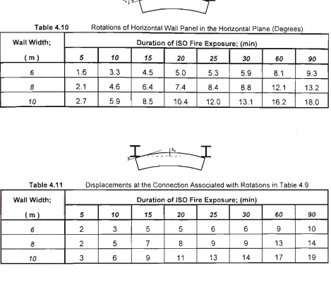
Table 4.7 Lateral Load Required to Maintain Critical Wall Deformation to 6|r 4 - 1 0 Table 4.8 Displacements of Horizontal Wall Panel in the Vertical Plane 4 - 1 9 Table 4.9 Displacements of Horizontal Wall Panel in the Horizontal Plane 4 - 1 9 Table 4.10 Rotations of Horizontal Wall Panel in the Horizontal Plane 4 - 1 9 Table 4.11 Displacements at the Connection Associated with Rotations in Table 4.9 4 - 1 9
Table 5.1 Summary of Testing Program 5 - 4 Table 5.2 Description of Test Samples 5 - 5 Table 5.3 Summary of Test Results 5 - 1 3 Table 5.4 Estimated Time to Failure of the Elevated Connection Tests 5 - 31
Table D.I Maximum Deflection of 6m Wall with Varying Levels of Discretisation D - 3
CHAPTER 1 INTRODUCTION
Single storey ^^rehouse buildings are a common form of construction. These buildings often
house large quantities of combustible materials, are rarely fitted with sprinklers, and often house
operations which are hazardous with respect to fire initiation.
It is not supnsing, therefore, that fires in such buildings are a frequent occurrence relative to the
frequency of fires in other commercial buildings. To date, there has been no evidence of death
resulting from fires in such buildings. This is probably attributable to the fact that most fires appear
to develop after hours when there are no or few occupants still present within the building.
Fires in these buildings are of concern to fire brigades as these fires tend to be very large.
Extinguishment of the fire is generally not possible and the role of the brigades is to assist with
preventing fire spread to the adjacent properties. This is usually done by playing water on the walls
of the adjacent buildings. Other important factors relevant to limiting fire spread, are the presence
of fire-resistant external walls and/or the spacing between the adjacent buildings.
The Building Code of Australia -BCA (1990), gives the fire-safety objectives of the regulations.
These are summarised as follows:
( i ) to provide an adequate level of safety for the occupants of the building and the fire
fighters;
( i i ) to provide an adequate level of protection for adjacent properties.
Traditionally f^0f^J^(pfm warehouse buildings have been constructed using steel frames and
masonry external walls. This was particularly the case where the external walls were required to be
considered to provide an adequate level of fire separation. Although the external walls within a
certain distance of the site boundary were required to have a fire-resistance level, the columns and
rafters were permitted to be unprotected and not required to achieve the level of fire-resistance
required for the walls. This situation is essentially the same today.
Changes in building fashion, technology, and construction economics have resulted in the external
walls of warehouse buildings being most commonly constructed using concrete panels. This is
sometimes the case even when a fire-resistant wall is not required.
The use of such concrete panels for the external walls of buildings has raised the question of
whether this form of construction can satisfy the above-mentioned objectives. To be specific, will
the panels become detached and fall outwards thus potentially endangering the life of fire fighters
outside the building and adjacent property? Are there special design considerations that should
apply to ensure that the above objectives can be achieved?
In this regard, the Building Code of Australia (1990), specifies the following:
C1.11 Performance of external walls in fire
( a) If a building having a rise in storeys of not more than 2 has concrete walls that could collapse as complete panels (eg tilt-up and precast concrete), they must be designed so that in the event of fire the likelihood of outwards collapse of the panels is minimised.
(b) Compliance with Specification C1.11 satisfies (a).
Amendment 7, Building Code of Australia
^Cj/i^^p||6\j^ ^QKisi<^\s tM:^bk>e\LS^tie6 in "it>ore,,W9ii; and givejf a detailed description of current
warehouse construction. The behavioural characteristics of these buildings are described using a
As might be expected, various design approaches have been proposed to ensure adequate
behaviour in fire. The approaches are summarised and reviewed JfTtDfiapter 2.
The occurrence of a fire within a warehouse building will result in heating of the inside faces of the
external wall panels, as well as the unprotected steel frame. Heating of the inside of the panel will
cause it to deflect substantially - and it is possible that the deflection of the panel may be in a
different direction to that of the frames to which the walls are attached. T 6 study the deformation
l a f e i ^ v i c g f r ^ w ^ , a npfnericat-model was developed ,by ttfe author, Thisr^model is desoRto^dlh
/^h;apt^3.
y
In Chapter 4 the model is used to study the behaviour of isolated vertical and horizontal panels
under various heating regimes. The model is then used to evaluate the critical aspect of the design
philosophy developed by O'Meagher et al. (1991).
( Not only are the panels and the frame heating up during a fire but also the connections. It is
important, therefore, for the behaviour of connections under elevated temperature conditions to be
determined. This is the pur'pose of the experimental work presented Chapter 5.
r
' It is intended that the work presented in this thesis will provide background and data relevant to the
CHAPTER 2 BEHAVIOUR OF SINGLE-STOREY INDUSTRIAL BUILDINGS IN FIRE - A REVIEW
2.1 introduction
The purpose of this chapter is to summarise and review the literature related to the behaviour and
design of single-storey industrial buildings in fire.
In recent years a number of researchers, particulariy in Australia, have attempted to understand
various behavioural aspects of these buildings in fire and various papers and reports have been
written that deal with these aspects as well as the principles for designing these structures.
The interest in the behaviour of these buildings has been largely generated from the debate about
whether it is necessary for the steel frames to be fire-protected in situations where the frames
provide lateral support to external wall panels, and from a concern about large concrete panels
falling outwards in the event of fire.
As noted in chapter 1, Clause C1.11 of Specification C1.1 of the BCA requires buildings with
concrete or reinforced masonry external walls to be designed, such that in the event of a fire, the
likelihood of outwards collapse of the wall is minimised.
According to Part A3 and Table C1.1 of the BCA, the single storey industrial buildings, which form
the subject of this thesis, are classified as Class 7, Type C construction. According to Table 5, a
building or compartment having an area of less than 3000 m2 must be surrounded by walls having a
fire-resistance level of 90 minutes if the walls are located closer than 3m from the fire-source
feature (normally the site boundary).
Spec. C1.1,2.5(a)
( i ) steel columns - except in a fire wall or common wall, a steel column need not have
an FRL in a building that contains only one storey.
In various situations, the use of unprotected steel roofing members is allowed.
Spec. 01.1, 3.5
(ii) Roof - A roof need not comply with Table 3 if its covering is non-combustible and the
building,
( a) has a sprinkler system installed throughout; or ( b ) has a rise in storeys of 3 or less; or
( c) is of Class 2 or 3; or
(d) has an effective height of not more than 25m and the ceiling immediately below the roof has a resistance to the incipient spread of fire to the roof space of not less than 60 minutes.
For a typical situation, (see Figure 2.1), the BCA requires the concrete wall panels to have an FRL
of 90/90/90. These numbers specify the performance requirements with respect to structural
adequacy, integrity and insulation. For a wall panel, integrity and insulation are essentially a
function of thickness and will easily be achieved provided the panel has sufficient thickness.
However it is important to note that typical wall panels will not achieve an FRL of 90 minutes with
External Concrete Wall Required to Have FRL
Steel Roofing Membrane
Figure 2.1 BCA Concession for Steel Columns
The BCA also stipulates, in Specification C1.1 - Clause 2.2, that members offering lateral support to
elements required to have a Fire Resistance Level (FRL), should have the same FRL. Therefore,
as the walls must be laterally supported at the top. Clause 2.2 strictly requires the frames to be
protected to achieve an FRL of 90 minutes. However, in Australia, there are no situations to date
where this has been insisted upon - essentially because in the past, protection of the frames has
never been required. This "support-of-another part" requirement, with respect to lateral support,
has been deleted or amended in Queensland, Victoria and South Australia so as not to apply to
these buildings.
The above dilemma, of whether to protect the steel frames or not, resulted in the initiation of an
Australian Uniform Building Regulations Coordinating Council (AUBRCC) project in 1989. This
project was undertaken by BHP - Melbourne Research Laboratories and attempted to address
some of the above issues. A report by O'Meagher et al. (1990) was issued in 1990. The report
argued that fire protection of the steel frames was not required to satisfy the regulatory objectives of
the BCA. It was argued that it is not necessary for wall panels to remain essentially vertical (as
would be required in a fire test) to provide adequate separation provided they remained attached to
External Concrete Wall acting as barrier
Deformed Steel Frame and Roof Structure
Internal Fire Position
Figure 2.2 Possible Deformed Shape of Single-Storey Industrial Building
Effective compartmentation is also a regulatory requirement under the BCA* As to what constitutes
effective compartmentation, for single-storey buildings, the BCA states that if an external wall is
located up to 3m away from a fire source feature then no provision for an FRL is required. From
this it is considered that if the external wall provides at least this level of fire separation then
effective compartmentation has been satisfied.
In some cases where the external concrete wall panels deform inwards, to the extent of almost
becoming horizontal, the end result is a formation of a greater barrier to fire than a non-fire resistant
wall located 3m from the boundary. This boundary exists regardless of the time at which large
deformations or collapse occurs, so long as the wall remains effectively intact (O'Meagher et al.,
1990).
It was recognised that such gross deformation may result in gaps opening up between panels. This
strictly constitutes failure of the wall with respect to integrity^ - however the panels, even in this
state are considered to provide a substantial and sufficient barrier to radiation and flame. Even if
large gaps do form, then the concrete wall is still effective in acting as a fire barrier - more so than
that of a non-fire resistant wall located 3m from the boundary. See also Part C3 Clause C3.1(a)(ii).
The importance of adequate connections between the panels and the supporting frame was also
The conclusions of the above report were accepted by AUBRCC and changes to Clause C2.2 are
currently being considered to bring regulation uniformity across the States.
2.2 Single-Storey Warehouse Buildings
In the case of single-storey industrial buildings incorporating steel portal frames, concrete cladding
panels can be either horizontal or vertical (see Figure 2.3).
Roof Bracing
Non L,oadbearing Horizontal Concrete Wall Panels
Non Loadbearing Vertical Concrete
Wall Panels
steel Rafter
Non Loadbearing Concrete Wall Panels Steel Portal Frame
NOTE: The Non-Loadbearing Concrete Wall Panels are Either Pinned or Fixed at the Base
Figure 2.3 A ^^ingfe-Storey Non-Loadbearing Portal Frame Industrial Building
In both cases, the panels are considered by the BCA to be non-loadbearing, with respect to gravity
loads, as they support self-weight and carry no forces from the roof structure. They are required
however to resist lateral wind loads. Horizontal panels are generally less than 2m in width and
resist wind loads by spanning between supporting columns and are generally supported with steel
150 mm Thick Concrete Wall Panel ( Horizontal or Vertical Panels )
Universal Beam Section
250 Grade Clip Plate High / Mild Strength Bolt
Figure 2.4 Typical Steel Clip Plate Bearing Connection
Vertical panels, on the other hand, span between the foundation and the roof and may be attached
by a variety of systems to the steel frames. There are a variety of different vertical panels, and
frequently an eaves tie member is provided to support adjacent panels under wind load conditions
(see Figure 2.5).
steel Column
- Steel Column
- Steel Column
Eaves Tie Member
-I
/ / /
Precast Concrete Wall PanelsEaves Tie Member
z
V
Interlocking Concrete Wall PanelsEaves Tie Member
-^
T
V
Tilt-Up Concrete Wall Panel( a )
( b )
( c )
Precast Concrete Panel
I
Clip Plate Detail Option 1
y
^ ^ ^ ^
High Strength Bolt/Ferrule Connection UB Section
( a )
Clip Plate Detail Option 2
- &
UB Section
Clip Plate Detail Option 3
Precast Conaete Panel
( b )
Figure 2.6 Methods of Connection for Support in Fire
In the past, most designers have designed and detailed connections with panel erection and wind
forces in mind. The importance of connections in the fire situation has become of critical
importance although in the past it was rarely considered.
As will be noted from Figure 2.6, a typical connection of the type assumed to offer support in fire
consists of steel clips connecting the panels directly to the column flanges or to an eaves tie
member. In both cases, the clip plate is bolted to the concrete wall panel via a threaded insert or
cast-in ferrule. The clip plate is often not welded to either the eaves tie member or the column
flange.
In the case of tilt-up construction, the concrete wall panels are cast on-site and are erected once
the slabs have cured. In contrast, precast panels are pre-fabricated off-site and then transported to
the site where they are erected into position along the external faces of the portal frame. Ease of
fabrication and transportation generally mean that precast concrete wall panels are smaller than
Once the floor slab is poured, the steel portal frame is able to be positioned and fixed into place.
The steel frame is generally rectangular in shape with single spanning frames spaced at regular
distances along the length of the building as shown in Figure 2.3. Bracing is provided in the roof to
facilitate resistance to end wall wind loading and to provide overall stability.
In practice, the roof sheeting in association with the puriins, can provide substantial in-plane bracing
at the roof level (Bryan, 1972). During the early stages of fire development it is likely that the roof
will continue to provide significant restraint - especially away from the fire (O'Meagher et al., 1990).
Once the portal frame is erected the concrete panels are then positioned in place by connecting the
base of the panel to the footing and the panels to the steel portal frame.
2.3 Building Behaviour in Fire
In the event of fire in a single-storey industrial building, there are a number of possible scenarios
depending on the severity of the fire (O'Meagher et al., 1990 and Gnanakrishnan, 1990). The steel
frames may undergo severe deformation; panels may deform significantly and become detached
from the supporting frame; alternatively, relatively little damage may occur.
In this chapter the influences of fire on a single frame, on an isolated wall panel, and on the overall
building are considered. The role of the connection between concrete panels and frame is also
discussed.
2.3.1 The Developing Fire Concept
• the quantity and orientation of combustibles stored within the building,
• the nature and geometry of the combustibles, and
• the degree of ventilation.
In a real fire situation, it is reasonable to assume that the fire develops slowly from the time of
initiation, with various parts of the roof and walls being heated at different rates. As the fire
escalates in size, so too does its' intensity. It Is likely that the growing fire will heat the adjacent
members differentially leading to variations in steel and air temperatures throughout the building.
This scenario has been described in terms of a "developing fire concept" by O'Meagher et al.
(1990).
The above authors consider that it is unlikely that a steel frame will be at a uniform high temperature
but that parts of a fire-affected frame will be at different temperatures.
Other gradients in temperature are likely. For example, it is likely that while the fire is small, the
highest air temperatures will be closest to the fire. As the fire further develops, the temperature
close to the roof will increase. However, substantial venting of the flames through the roof will
probably result in a reduction of air temperature near the roof members.
2.3.2 Frame Behaviour
The behaviour of a steel frame in fire is now considered.
Much can be learnt from studying the geometry of buildings after the occurrence of fire, and
post-fire observations associated with a number of large post-fires in steel-framed industrial buildings, jffp
^p€[rTO4 ill4pp'en^b^ A: Some of the observations have been reported in the literature whilst others
Observations of post-fire industrial buildings show the steel frame structure having deformed and
distorted away from the external concrete wall panels. Due to the heat transfer effects of the
Internal fire, the steel roof members have a tendency to feel the effects of the fire prior to other
structural components within the building and tend to warp and collapse under their own self-weight.
The frame then collapses inwards as the rafters sag and collapse forcing the steel columns to follow
this deformation due to the rigid connection that exists between the column and the rafter at the
haunch.
A number of publications have addressed the behaviour of the frames in fire and these are now
considered.
Constrado - [1980]
In 1980, Constrado published a document entitled "The Behaviour of Steel Portal Frames in
'/ Boundary Conditions". At this time the building regulatory authorities in the United Kingdom were
suggesting that perhaps it was necessary to fire protect the entire portal frame assembly, as
opposed to just the columns. This document was prepared in response to this issue.
In the United Kingdom, it is very rare for portal frame buildings to have concrete panels as wall
cladding. Due to the climate, specific thermal insulation requirements must be achieved and walls
are either of insulated steel or masonry construction. Therefore this publication does not consider
the interaction between concrete wall panels and frames.
Regulations in the United Kingdom, require only the column to be protected. This has always been
the case.
According to this publication, as the fire escalates in growth and intensity, the members within the
roofing membrane are affected the most. As the temperatures increase within this upper region of
the building, the strength and stiffness of the structural steelwork are reduced. The steel rafters
tend to heat up and expand which Initially causes an outward movement of the eaves. This results
in the formation of plastic hinges close to the eaves as the bending moments at the eaves increase.
The combination of Increased bending moments and axial force in the rafter (see Figure 2.7) was
recognised as leading to fiexural - torsional buckling such that the rafter may end up with its web in
a horizontal position.
induced axial compression
F - ^ bending moment induced by rafter 1^ expansion
Figure 2.7 Forces and Moments Acting on the Portal Frame Members - Free Body Diagram
As the rafter undergoes gross deformation downwards, the columns will be pulled inwards.
The above publication suggests that adequate frame behaviour will be achieved if the base
connections of the frame have sufficient moment capacity. The required capacity was determined
as follows:
( i ) observation of some actual fires in warehouses suggested that typical deformations were
( i i ) assuming this displaced shape, and the position of the point of contraflexure within the
rafter, the bending moment at the base required for equilibrium was determined.
( i i i ) the base connection, which is protected because the column is protected, must be
designed to achieve this capacity. In practice this is relatively easy to achieve. "Pinned
connections" are not recommended.
The above approach is based on the assumption of a symmetrical fire and of a certain firame
geometry. In Australia, at least, column rotations - even when columns have been protected - have
often been found to exceed the assumed 1°. Column rotations of more than 15° have been
obtained (see Appendix A). The final geometry of the frame is dependent on the severity of the fire.
The Constrado publication also recognises that frames that have collapsed inwards (ie. the frames
nearest the point of fire origin) will provide some restraint to the remainder of the steel structure,
thus minimising the chances of an outwards overall collapse.
Gnanakrishnan - [1993]
The report prepared by Gnanakrishnan, (1993), entitled "Likely Fire Performance of One and Two
Storey Buildings witii Precast Concrete or Tilt-up Panels or Precast Concrete Cladding", does not consider frame behaviour in a quantitative manner but makes a number of general post-fire
observations.
Gnanakrishnan analysed the behaviour of various structural components subject to fire but did not
attempt to analyse the entire building structure subject to these conditions.
The development of a typical industrial building fire was considered qualitatively with respect to the
likely behaviour of the entire building subject to various fire exposures. The fire scenarios
considered were:
( i ) internal fire adjacent to an external wall
( i i ) internal fire adjacent to an internal wall
(Iii) internal fire at the corner of a building
(iv ) internal fire, (not reaching the roof), on the ground floor
( V ) internal fire spread throughout the building
( v i ) external fire near a wall
Gnanakrishnan concludes that intensity, spread and duration of the fire in a building are dependent
on the initial fire source, availability of fuel, building size, building openings and ventilation. The
problem of analysing the fire behaviour of the entire building structure was recognised as being too
difficult due to the large number of contributing factors.
Gnanakrishnan observes that modern industrial buildings of this type often contain a vast variety of
stored goods; varying in both quantities and volatility and that it is because of this that high
temperatures can occur within these buildings. The combination of severe fires and unprotected
steel is considered to give rise to substantial deformations of the frames.
Gnanakrishnan describes the behaviour of the steel column / concrete wall panel interface as
follows:
loss in strength due to increased fire exposure. These additional forces would cause the connections to fail and would result in the wall cladding collapsing."
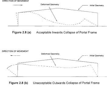
O'Meagher et al. - [1990]
In 1990, a report was published by BHP Research - Melbourne Laboratories (O'Meagher et al.)
which addressed the behaviour of these buildings. In a later paper, O'Meagher et al. (1992)
explained and expanded the contents of the above report. The investigation described in these
publications was undertaken to determine whether steel frames have a tendency to collapse
"inwards" or "outwards" in the event of a fire. These two possibilities are shown schematically in
Figure 2.8 (a) and 2.8 (b).
DIRECTION OF MOVEMENT
Deformed Geometry Initial Geometry
Figure 2.8 (a) Acceptable Inwards Collapse of Portal Frame
DIRECTION OF MOVEMENT
Deformed Geometry
Initial Geometry
Figure 2.8 (b) Unacceptable Outwards Collapse of Portal Frame
The above approach involved analysis of single-storey industrial buildings incorporating steel portal
frames. Investigation of both the steel portal frame and the attached cantilevered concrete walls in
fire was undertaken to provide an overall understanding of behaviour for single-storey industrial
Some of the key factors that were taken into account were:
( i ) the effect of elevated temperature on steel properties,
( i i ) the effect of differential heating,
(iii) the effect of second-order displacements on frame behaviour,
( i v ) the presence of a lateral in-plane restraint to the frame from the roof,
(V ) the restraint provided by the column base connections, and
( vi) loads due to the attached extemal concrete walls and the portal roof structure.
Cool Zone
3T/4
Situation A
Cool Zone
-Situation C
3T/4
^
Cool Zone
Situation B
Situation D
Cool Zone ^ / l^
Situation E
Cool Zone
h
Cool Zone .—/ I Cool Zone
S i t u a t i o n F
Temperature. T
Cool Zone
Situation G
Figure 2.9 Heating Situations Considered by O'Meagher et al. (1990)
The frames were analysed using the finite element program ABAQUS with the frame temperature
being increased until very large displacements occurred.
As a result of the above analyses, it was found that plastic hinges (regions of extensive plasticity)
were formed at or near one end of the rafter and within the rafter close to the end of the heated
region. These hinges are caused by the yielding of the rafter as the yield stress of the steel falls
with an increase in temperature and as the bending moments due to thermal effects increase.
The analyses results showed that the desired frame deformation (see Figure 2.8 (a)) will, in
connections, desirable frame deformations ("inwards" deformations) were obtained for all
unsymmetrical frame temperature distributions. In practice, unsymmetrical ft-ame temperature
distributions will always occur. However, even for ft-ames with unifonn temperature distribution, the
desirable deformations occurred provided a small degree of moment resistance was present at the
base connections. The level of resistance required will be easily achieved by practical base details.
That desirable frame geometries are obtained in real fires is supported by the findings presented in
Appendix A.
It was also recognised that as the fire develops within a building, and as the frames progressively
deform, the frames will act as "anchors" to the rest of the building.
^ ^
2.3.3 Wall Behaviour
In this section, the behaviour of wall panels under fire conditions is considered.
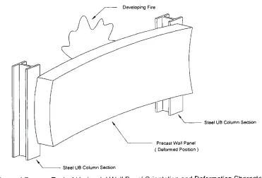
As can be seen from the case studies given in Appendix A, concrete walls subject to an internal fire
will tend to deflect outwards, provided they are effectively fixed at the base. This is principally due
to differential thermal expansion of the wall as illustrated in Figure 2.10; (O'Meagher et al., 1990 and
Gnanakrishnan, 1993).
Original Wall Position
Cantilevered Concrete Wall Panel
Developing Fire
If the vertical wall panel is dowelled at the bottom, and supported laterally at the top, it will behave
as if it is a cantilever due to prying against the column flange. Tffi|t^ aspect of behaviour is
^^fe^Lisseciat^^ome^lerrgth in Chapter<
Constrado (1980), does not consider the behaviour of any attached concrete walls, as in the United
Kingdom, walls are almost entirely insulated steel or masonry construction.
O'Meagher et al. (1991), have looked extensively at the behaviour of reinforced and prestressed
concrete wall panels under fire conditions. ^;eValu^tIoh of isolated wall behaviour is presented in
Cf>^pter S'^usrqg a variation of the methbd used by O'Meagher and Bennetts, (1991). Both vertical
and horizontal panels are considered.
Gnanakrishnan (1993), considers that concrete wall panels may suddenly fall either inwards or
outwards without any visible sign of warning. This scenario is both undesirable and unacceptable
and, as noted previously, may result in damage to adjacent buildings or persons. However, it is
difficult to see how inwards collapse - particulariy if the panel movement is controlled by the
deforming frame - can have an adverse infiuence on life safety. In order to obtain such
deformations, the fire must be well developed within the building - well beyond the stage that
firemen would be able to fight the fire from within the building.
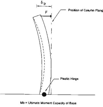
Gnanakrishnan (1993) analyses what is purported to be a "standard" wall panel. The panel was a
190 mm thick reinforced concrete wall panel, 8 m in height and subjected to a standard fire
exposure. The wall reinforcing details are not given.
The wall was analysed using a special purpose finite element program. The boundary conditions
assumed for the wall are illustrated in Figure 2.11. The forces at the connection, (assumed to be at
the rafter level) were determined. The lateral supporting structure was considered to be infinitely
No account was taken of the interaction of the wall curvature with columns - there is a basic
incompatibility between the straight column flange and the wall curvature.
fixed support supporting
steel roof
developing fire
cantilevered concrete
wall panel Wall as analysed
schematically
footing
Figure 2.11 Behaviour of Cantilevered Concrete Wall in Tilt-Up Construction; (Gnanakrishnan, 1993)
It is Gnanakrishnan's view that canfilevering the base of the concrete wall is beneficial and will
minimise the likelihood of outward collapse. He suggests that in cases where the concrete wall
panel is pinned at its base, the connection at the top of the wall must remain intact in order for the
wall panel to stay attached to the supporting structure.
2.3.4 Support of Walls
This matter has been considered by both O'Meagher et al. (1990) and Gnanakrishnan (1993).
O'Meagher et al., (1990), consider that integrity of the connection between panels and frame is
essential in minimising the likelihood of outwards collapse.
If vertical wall panels are effectively fixed at the base, they will deflect outwards away from the fire,
and as noted previously, the steel frames may undergo substantial deformation with one column
moving inwards - ie. in the opposite direction to the wall. It is clear, therefore, that the connections
work by O'Meagher et al. (1994), has attempted to establish appropriate design criteria for such
connections.
The importance of both strength and ductility to a connections' behavioural aspects is reinforced by
some real fire s i t u a t i o n s ^ ^ i ^ ^ ^ ^ j f f ^pendix^A. These issues of strength and ductility are
/corisi/iered in greater detail in Chapter^ 4 and 5.
I Gnanakrishnan (1993), recognises the importance of connection strength but makes no reference
to ductility requirements - "failure of the connections is the most important contributory factor to the !
j instability of the wall panels".
It is recognised that the frame columns may deform in the opposite direction to the wall panels, with
the possibility of significant forces being developed. Gnanakrishnan found that initially the forces
are greatest in the early stages of fire growth and then reduce in magnitude as the structural
components become affected by fire. The force in the rigid connecfion, associated with the
situation shown in Figure 2.11, was esfimated by Gnanakrishnan to reduce to 50 kN/m after 90
minutes of standard fire exposure. Some serious questions have to be asked about the validity of
this result as it seems unlikely that the wall could support a base bending moment of 50 x 8 = 400
kN-m per metre width of wall. Typical walls have an ambient base capacity per metre of
approximately 5 - 1 0 kN-m per metre width of wall. As noted above, the reinforcing details
associated with the analysed wall are unknown. It appears unlikely therefore, that the above result
can be considered as representative of normal construction.
Moreover, the restraint force will be limited by the ability of the supporting member to plastically
deform and the degree of deformation that the frame experiences. These factors were ignored by
Gnanakrishnan.
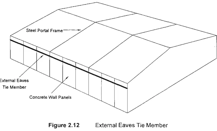
reason he recommends that connections and supporting members are provided along the outside
face of the wall. It is recommended that a lightweight eaves member can be run around the outside
of the building as illustrated in Figure 2.12. This member is to be designed to resist the lateral
forces applied by the outwardly bowing concrete wall panels.
External Eaves Tie Member
Concrete Wall Panels
Figure 2.12 External Eaves Tie Member
However, the authoiSconsider<|'this recommendation to have limited appeal due to the additional
cost, architectural appearance, and concerns about corrosion. Furthermore, this system will only
work provided the eaves member is capable of acting as a catenary member - a light channel may
not have sufficient bending strength. The member should be connected to each frame and at the
end of the building would need to be properiy anchored. These aspects are not mentioned by
Gnanakrishnan who appears to assume that the eaves member can span from one end of the
building to the other. This could only be achieved if the member acts as a cable and would require
effective anchorage at the ends of the building (see Figure 2.13). It is extremely difficult to see how
Plan of Building
Forces Applied from Extemal Wall Panels Anchorage Required Eaves Tie Member
Figure 2.13 Anchorage of External Eaves Tie Member
Alternatively, O'Meagher et al. (1990) consider that the use of non-fire rated connections is not a
major problem with regards to providing adequate structural behaviour provided they have sufficient
strength and ductility.
Gnanakrishnan also considers the use of nylon bolts to connect the wall panels to the supporting
structure. If the panels are cantilevered, the use of such bolts, it is argued, will allow the separation
of structure and panels such that the panels will continue to resist the fire effects through cantilever
action. The unprotected steel frame will therefore, in theory, be allowed to collapse without
affecting the structural adequacy of the external walls.
In the opinion of the autho]]J>this is a dubious approach - especially for practical walls with minimum
quantities of reinforcement./As will be shown in Chapter 4. pese walls do not exhibit a high level of
fire-resistance as isolated cantilevers, and given a fire of sufficient magnitude, may well collapse
2.4 Summary of Design Philosophies y
The different design philosophies are now summarised as follows:
According to the Constrado publication, (1980):
1. portal frame rafters do not require fire protection;
2. the foundations, column and column base should be designed to resist the overturning moment
at the base of the column - assuming a nominated frame geometry;
3. protection of the column has always been required in the United Kingdom. The validity of this
requirement was not addressed.
Alternatively, Gnanakrishnan (1993) gives the following design recommendations that:
1. adequate base capacity for the wall must be provided;
2. the provision of a continuous eaves tie should be provided on the outside of the building - no
details are given regarding connection of this external tie member to the supporting columns;
3. the size of the above mentioned eaves tie should be designed to resist a force of
approximately 50 kN/m per metre width of wall. As noted previously, it is difficult to see how
forces of this magnitude can be achieved or resisted.
On the other hand, O'Meagher et al. (1994) have suggested the following philosophy:
1. the steel frames, in the event of a fire, will deform in a safisfactory manner;
2. provided the panels remain attached to the portal frame they will not collapse outwards;
3. the connections between the steel supporting structure an the concrete panels must be
designed to have sufficient ductility and adequate strength at elevated temperature;
4. adequate allowance for relative movement between the concrete wall panel and the structural
CHAPTER 3 MODELLING OF CONCRETE WALLS IN FIRE
3.1 Introduction
In this chapter a mathematical model is developed to study the structural behaviour of reinforced
concrete walls when subject to elevated temperatures due to fire on the internal face.
As highlighted in the previous chapters, the interaction between the supported external walls and
the supporting steel structure is of critical importance in determining whether the separation of wall
and structure will occur, and it is the deformation and resistance of the external walls that, to a large
extent, determines the forces developed at the connections between the frame and the wall. The
analysis model described in this chapter is used in Chapter 4 to study the behaviour of some typical
walls and to provide some insights into the design requirements for connections.
In developing the mathematical model described in this chapter, a number of convergence
problems were encountered. These problems are discussed.
3.2 Elevated Temperature Analysis
To model the behaviour of concrete walls subject to elevated temperatures, it is necessary to
determine the temperature distribution across the wall at any given time. This is achieved through
analysing the heat fiow characteristics through the concrete wall for a given imposed heafing
situation.
the building. The former situation will generally subject the wall and the structure to the most
intense heat and Is therefore exclusively considered in this study.
The calculation of temperatures throughout the wall was undertaken using the finite element
program TASEF-2 (WickstrOm, 1983). The program is a transient two-dimensional heat flow
analysis and enables a number of materials to be considered, including concrete and steel.
Conservative thermal properties (i.e. properties likely to give higher than normal temperatures for
thermal conductivity, heat capacity and moisture content) are adopted for concrete. Any heating
situation can be imposed on one face of the wall by specifying a time-temperature relationship, and
appropriate values of radiative and convective heat transfer coefficients. Specific coefficients are
recommended for simulating the standard fire test heating environment (WickstrOm, 1983).
In practice, as noted in the previous chapter, real fires are highly variable. For the purpose of the
analysis conducted in Chapter 4, the fire is assumed to correspond to an ISO standard fire of some
duration. The use of the ISO standard fire exposure relationship is adopted not only for simplicity
but also because it will enable a good estimate of the relative performance of the concrete walls
subject to various fire scenarios and because it is the basis for current regulatory requirements for
walls. The vast majority of fire engineering designs are based at present on the standard fire
exposure (Twilt, 1988).
In the standard fire test it is required that the temperature-time relationship follows the following
equation.
Tf = To + 345 logio (480t +1) Eq. ( 3.1 )
where:
Tf Fire Temperature (°C)
To Ambient Temperature (°C)
To calculate the temperatures through the wall using TASEF-2, the wall must be discretised across
its thickness into a number of elements. The appropriate fire-time temperature curve and heat
transfer coefficients, and the material thermal properties must also be specified. Comparison of
temperatures predicted using TASEF-2 with measured temperatures obtained during standard fire
tests (The Institution of Structural Engineers, 1978) indicate good agreement, with the predicted
temperatures being generally greater nearer to the heated surface; see Figure 3.1 .
The temperatures through a 150 mm wall, when subject to 30, 60 and 90 minutes of standard fire
test exposure on one side of the wall are shown in Figure 3.1.
u
D> 0) Q 3 4-1s
o o. E K-5
1000 900 800 700 600 ^ 500 400 300 200 100 A^ ' . ^ J
\ \ X*
^ \ ^
>^^
^ >
' ''^ "-i l Z ^ J:-:
1^ o r - CO
LO o CO
If) 1^ o
in O o
CM
in
CO
o
in Distance From Heated Face, (mm)
TASEF 30 min TASEF 60 min TASEF 90 min - • Experimental 30 min
< Experimental 60 min ^ Experimental 90 min
Figure 3.1 Standard Fire Temperature Gradients at Varying Times of Exposure for 150 mm Thick Concrete Wall - [TASEF-2 versus Experimental Results]
3.3 Modelling of the Wall
For the purpose of developing a mathematical model, the cases shown in Figure 3.2 have been
considered. The situation shown in (a) represents a vertical wall panel which is effectively
rotationally restrained at the base and subject to a horizontal load at the top of the wall in addition to
its own self weight acting in a vertical direction (see also Figure 3.3). As will be demonstrated in
Chapter 4, this situation always occurs where a vertical panel is connected to a steel frame such
that it is directly adjacent to a column. The situation shown in (b) represents a horizontal wall panel
which is partially rotationally restrained at each end of the panel at the column support via a clip
connection. This often occurs where a horizontal panel is connected to a steel frame.
Deformed Panel
-r \ \ \ " x 1 \ \ \ 1 \ \ \ 1 \ \ ] 1 Portal Frame Fire Portal Frame
VERTICAL PANEL CASE HORIZONTAL PANEL CASE
(a) (b)
Figure 3.2 The Two Cases Analysed for the Wall Model Study
The above cases were modelled as shown in Figure 3.3 .
Lateral Load, P
Vertical Panel Rotational Restraint
Fire
Fire
Horizontal Panel
%
HORIZONTAL PANEL CASE (PLAN VIEW)
(b) VERTICAL PANEL CASE
(a)
The method of analysis presented in this chapter assumes that the wall can be analysed as a
one-way member with curvature in only one direction. This is likely to lead to an over-estimate of
displacements. Nevertheless, it is a reasonable and conservative assumption.
3.3.1 Discretisation of Wall Model
For the purpose of analysis, the wall is discretised across its thickness and length as shown in
Figure 3.4.
The analysis program allows for different numbers of elements and segments.
Exposed to Standard Fire Time-Temperature
Curve
Unit
Segments Length
Figure 3.4 Discretisation of the Cantilevered Concrete Wall
The effect of increasing the number of segments up the wall has been investigated and the results
3.3.2 Constitutive Equations
In order to determine the structural behaviour of the concrete wall under elevated temperature
conditions, it is necessary to allow for the effect of elevated temperature on the mechanical
properties of both the steel reinforcing and the concrete.
According to Anderberg (1973), the strain state associated with a concrete element can be broken
up into the following:
etot = sth + Sa + ^cr + str
where:
Sfot
Hh
Ear
etr
Eq.( 3.2 )
total strain of the specified element
free thermal expansion of the material at a given temperature stress related strain
creep, (or time-dependent), strain of the concrete and/or steel
transient strain of the material
In equation 3.2 above, St^ is a function of temperature, 8^ is a function of stress level and
temperature, EQJ- is a function of stress level, time, and temperature, and Sfp considers the effect of
stress history on deformation at elevated temperatures.
The strain state within the steel reinforcing element can be represented in a similar manner
-although in this case, transient strain is not appropriate.
For the purposes of the model developed in this chapter, the thermal expansion relafionships
recommended in Eurocode 4 (Schleich et al., 1990) have been adopted whilst the stress-strain
relationships recommended in Eurocode 2 (Dotreppe et al., 1990) have been adopted. Typical
stress-strain relationships for reinforcing steel and concrete are shown in Figures 3.5 and 3.6,
For concrete, the transient strain term, 8tr_ and the creep strain term, 8cr> have been implicitly (and
appropriately) included in the Eurocode 4 stress-strain relationships. Thus, only thenmal and stress
related strains are explicitly considered.
For steel reinforcement, creep effects are only significant for temperatures greater than 450 °C
(Williams-Leir, 1983).
Again, the creep effects are implicitly included in the Eurocode 4 stress-strain curves for steel. It is
important to note that Eurocode 4 recommends different stress-strain relationships for reinforcing
steels - depending on whether the steel is cold-worked or not. Reinforcing fabric is manufactured
from hard drawn wire and is most commonly used to reinforce concrete walls. It is rare that Y bars
are used.
Therefore the appropriate stress-strain relationships for steel reinforcement, for the analyses
undertaken in Chapter 4, are those corresponding to cold-worked reinforcing steel as shown in
Figure 3.5.
^ / f a y ( 2 0 % )
8 ( 6 ) % 0 0.5 1.0 1.5 2.0
Figure 3.5 Stress-Strain Relationships for Reinforcing Steels at Elevated Temperatures
^/fc(20%)
Figure 3.6
e(e)%
Stress-Strain Relationships for Siliceous Concrete at Elevated Temperatures
The majority of concrete used in Australia in the manufacture of concrete walls use siliceous
3.3.3 Strain State within A Segment
Within any segment down the wall it is assumed that the deformation of the elements is such that
plane sections before deformation remain plane after deformation.
It is also assumed that the curvature within a segment is constant over the length of the segment.
With the strain state within a segment assumed to be constant, the stress state can be determined
through satisfaction of the equilibrium equations given below in Section 3.3.4.
3.3.4 Equilibrium Equations
The equilibrium situafion associated with a deformed wall is shown in Figure 3.7 and is described by
the following governing equations.
N D
j segment twundary
Figure 3.7 Equilibrium Equations for the Cantilevered Wall
where:
j = segment/boundary number
"i = total number of elements analysed
rij = total number of segments analysed
At each segment boundary the following equilibrium equations must be satisfied:
The Resultant Force, Fr, at the jt^^ segment boundary = 0 :
i.e. F, = 0
But, ^r=^mt-^exl Eqs. ( 3.3 )
Equating the above equations, we have:
Fr=feii|-|iWi+N
M V {U ' J
= 0
Eq. ( 3.4 )
The Resultant Moment, Mr, at the jt^ segment boundary about 'a' = 0
M, = 0
But, M , = M i - M , Eqs. (3.5)
Equafing the above equations, we have:
M,=(|;Vy,)-(iw,.d,-P.h,.N.D] = 0 ^^^^^_^^
For the wall to be in equilibrium each segment boundary must satisfy the above equations.
3.3.5 Compatibility Equations
In addition to the equilibrium equations, it was necessary to determine the relationships between
segment rotation, curvature and lateral displacement.
Given the curvatures of the wall at each of the segment boundaries, the deflected shape can be
determined using the following equations; see Figure 3.8.
2
\
" l
1
^
^
tr
k ^
PosmonTP.*
S
• l \ \
e._ p . * .
\ p ^ 4 , ^ \ 0
Figure 3.8 Geometric Relationships Between Successive Points on a Curve
where;
6 is the slope at the element boundary
^ is the curvature at the element boundary p is the element length
V is the lateral displacement at the element boundary
V 2 = V , + P A - ^
0 2 = 6 i - p 2 ^ 2 Eqs. ( 3 . 7 )
and so forth with the deflection and the rotation of the f-^ point detennined as follows:
pfO,
® i = ^ H - P i ^ i Eq.(3.8)
For a cantilevered wall, the displacement and rotation at the base of the wall are zero. The
displacements and rotations for points above the base are easily determined from the above
geometric equations.
3.4 Method of Solution
The non-linear behaviour of concrete and steel at elevated temperatures, and the fact that
Equations 3.3 - 3.8 are interdependent, means that an iterative solution procedure must be
adopted.
Newton's Iteration Method, (La Fara, 1973), was used for solving the above simultaneous
equations. This method is described below.
Assuming the resultant axial force (refer to Equation 3.4) associated with equilibrium of a wall cross
section is represented by the symbol Fr, and the resultant bending moment about 'a' (see Figure
3.7) resulting from the internal and external forces is given by Mr (refer to Equafion 3.6), the