Relativistic Electron Mirrors
from High Intensity Laser
Nanofoil Interactions
Daniel Kiefer
Relativistic Electron Mirrors
from High Intensity Laser
Nanofoil Interactions
Dissertation
vorgelegt vonDaniel Kiefer
geboren in Uelzen
angefertigt am
Max-Planck-Institut für Quantenoptik
Fakultät für Physik
Abstract
The reflection of a laser pulse from a mirror moving close to the speed of light could in prin-ciple create an X-ray pulse with unprecedented high brightness owing to the increase in photon energy and accompanying temporal compression by a factor of 4γ2, whereγis the Lorentz fac-tor of the mirror. While this scheme is theoretically intriguingly simple and was first discussed by A. Einstein more than a century ago, the generation of a relativistic structure which acts as a mirror is demanding in many different aspects. Recently, the interaction of a high intensity laser pulse with a nanometer thin foil has raised great interest as it promises the creation of a dense, attosecond short, relativistic electron bunch capable of forming a mirror structure that scatters counter-propagating light coherently and shifts its frequency to higher photon energies. However, so far, this novel concept has been discussed only in theoretical studies using highly idealized interaction parameters.
Zusammenfassung
Wird ein Lichtpuls von einem Spiegel reflektiert der sich mit nahezu Lichtgeschwindigkeit bewegt, kommt es auf Grund des relativistischen Dopplereffektes zu einer Erhöhung der Photo-nenenergie und einer damit verbundenen zeitlichen Kompression um einen Faktor 4γ2, wobeiγ der Lorentzfaktor des Spiegels ist. Dieses faszinierend einfache Konzept zur Generierung inten-siver, kurzwelliger Strahlung wurde erstmals von A. Einstein vor mehr als einem Jahrhundert diskutiert. Jedoch ist die Erzeugung einer relativistischen Struktur, die sich zudem auch noch spiegelartig verhält, in vielerei Hinsicht äußerst anspruchsvoll. Kürzlich wurde gezeigt, dass die Interaktion eines hochintensiven Laserpulses mit einer Nanometer dünnen Folie einen extrem dichten, Attosekunden kurzen, relativistischen Elektronenpuls generieren könnte, der wiederum in der Lage wäre, gegenläufiges Licht kohärent rückzustreuen und gleichzeitig zu höheren Pho-tonenenergien zu verschieben. Dieses neuartige Konzept wurde bisher jedoch nur theoretisch und mit stark idealisierten Laserpulsen untersucht.
Contents
Abstract v
Zusammenfassung vii
Contents ix
List of Figures xiii
1 Introduction 1
1.1 Thesis Outline . . . 4
2 Theoretical Background 5 2.1 Fundamentals of Light . . . 5
2.2 Single Electron Motion in a Relativistic Laser Field . . . 7
2.2.1 Symmetries and Invariants . . . 7
2.2.2 Single Electron Motion in a Finite Pulse . . . 10
2.2.3 The Lawson Woodward Principle and its Limitations . . . 11
2.2.4 Acceleration in an Asymmetric Pulse . . . 12
2.2.5 Ponderomotive Scattering . . . 13
2.2.6 Vacuum Acceleration Schemes . . . 14
2.3 Laser Propagation in a Plasma . . . 16
2.3.1 Laser Interaction with an Overdense Plasma . . . 17
2.3.2 Relativistic Electron Mirrors from Nanometer Foils . . . 20
2.4 Relativistic Doppler Effect . . . 22
2.5 Coherent Thomson Scattering . . . 23
2.5.1 Analytical Model . . . 24
2.5.2 Reflection Coefficients . . . 27
3 Experimental Methods:
Lasers, Targets and Detectors 31
3.1 High Power Laser Systems . . . 31
3.1.1 Laser Pulse Contrast . . . 33
3.1.2 Utilized Laser Systems . . . 35
3.2 Diamond-Like Carbon (DLC) Foils . . . 39
3.3 Diagnostics . . . 43
3.3.1 Working Principle . . . 43
3.3.2 Electron Spectrometer . . . 44
3.3.3 Multi-Spectrometer . . . 46
3.3.4 Image Plates . . . 49
3.3.5 Scintillators . . . 50
4 Electron Acceleration from Laser-Nanofoil Interactions 51 4.1 PIC Simulation . . . 52
4.2 Experimental Setup . . . 57
4.3 Ion Measurements . . . 59
4.4 Target Thickness Scan . . . 60
4.4.1 Experimental Observations . . . 60
4.4.2 Theoretical Discussion . . . 63
4.5 Electron Blowout . . . 67
4.5.1 LANL . . . 67
4.5.2 MBI . . . 70
4.5.3 Theoretical Discussion . . . 71
4.5.4 Competing Mechanisms . . . 75
5 Coherent Thomson Backscattering from Relativistic Electron Mirrors 77 5.1 Experimental Setup . . . 77
5.1.1 Spatio-Temporal Overlap . . . 80
5.2 Experimental Results . . . 81
5.3 PIC Simulation . . . 85
5.3.1 Spectral Analysis . . . 86
5.3.2 Temporal Analysis: Reflection from a Relativistic Electron Mirror . . . 88
5.3.3 Electron Mirror Properties . . . 91
5.3.4 Electron Mirror Reflectivity . . . 94
Table of Contents xi
6 Conclusions and Outlook 97
6.1 Summary of the Results . . . 97 6.2 Future Perspectives . . . 99
A Plasma Mirrors 103
A.1 ATLAS Plasma Mirror . . . 105
B Spectrometers 111
B.1 Wide Angle Electron Ion Spectrometer . . . 113
Bibliography 115
Publications by the Author 133
List of Figures
1.1 Laser-driven, relativistic electron mirror from a nanoscale foil . . . 3
2.1 Single electron motion in a plane wave . . . 10
2.2 Single electron in a finite pulse . . . 11
2.3 Single electron in an asymmetric, finite pulse . . . 12
2.4 Ponderomotive scattering . . . 14
2.5 Laser-driven, relativistic electron mirror from a nanometer foil . . . 21
2.6 Relativistic Doppler effect . . . 22
2.7 Dependence of the opt. electron bunch thickness on the upshifted radiation 26 2.8 Dependence of the electron bunch form factor on the bunch thickness, shape 27 2.9 Dipole emission from a single electron . . . 28
2.10 Relativistic Doppler upshift from laser-driven electron mirrors . . . 29
3.1 Chirped pulse amplification scheme . . . 31
3.2 Illustration of a typical laser pulse contrast curve . . . 33
3.3 MBI and LANL contrast . . . 38
3.4 Astra Gemini contrast . . . 38
3.5 Microscope image of a free-standing DLC foil . . . 39
3.6 Image of a heated, free-standing DLC foil . . . 41
3.7 Laser target damage threshold . . . 42
3.8 Electron spectrometer setup . . . 45
3.9 Multi-Spectrometer: Photograph . . . 46
3.10 Multi-Spectrometer: Setup . . . 47
4.1 PIC simulation snapshots . . . 55
4.2 Electron energy space in the transparency regime . . . 56
4.3 Temporal evolution of the laser-nanofoil interaction . . . 56
4.4 Experimental setup: LANL . . . 57
4.6 Ion energies observed at LANL and MBI . . . 59
4.7 Typical electron spectra observed at LANL, MBI and RAL . . . 62
4.8 Electron mean energies observed from different lasers and foil thicknesses 63 4.9 LANL electron blowout spectra measured at 0 deg . . . 67
4.10 LANL electron spectra from a 300 nm foil: Angular dependence . . . 68
4.11 LANL electron blowout spectra: Angular dependence . . . 69
4.12 LANL electron blowout spectra: Footprint . . . 69
4.13 Electron blowout spectra: MBI . . . 70
4.14 Electron blowout: PIC simulation spectra, electron emission characteristic 72 4.15 Electron blowout: PIC simulation field ionization . . . 72
4.16 Electron blowout energy scaling . . . 74
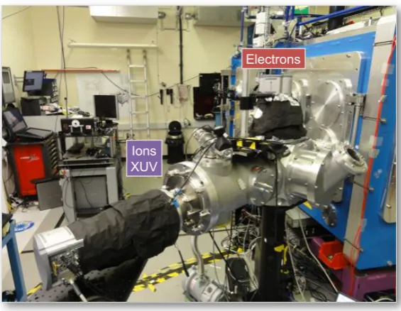
5.1 Photograph of the experimental setup. . . 78
5.2 Schematic illustration of the experimental configuration . . . 79
5.3 Pulse synchronization . . . 80
5.4 XUV spectra from different targets and laser pulse configurations . . . 82
5.5 XUV spectra: Detector images . . . 83
5.6 Integrated XUV signal from different targets and laser pulse configurations 83 5.7 Electron spectra . . . 84
5.8 PIC simulation configuration . . . 85
5.9 Drive spectra . . . 87
5.10 Probe spectra . . . 88
5.11 Reflection from a relativistic electron mirror . . . 90
5.12 Backscattered pulse train . . . 91
5.13 Electron mirror properties - time series I . . . 92
5.14 Electron mirror properties - time series II . . . 93
5.15 Electron mirror reflectivity . . . 96
A.1 Plasma Mirror working principle . . . 103
A.2 Double plasma mirror setup at LANL . . . 104
A.3 ATLAS Plasma Mirror: engineering design . . . 106
A.4 ATLAS Plasma Mirror: optical setup . . . 108
A.5 ATLAS laser pulse contrast measurement . . . 109
B.1 Magnets used in the electron spectrometer . . . 111
B.2 Spectrometer dispersion curves and spectral resolution . . . 112
Chapter 1
Introduction
Soon after the first demonstration of the laser [1], the quest for a coherent light source at even shorter wavelengths emerged. Nowadays, intense, brilliant X-ray beams are ob-tained from large-scale synchrotrons and have become an indispensible tool in many areas of science and technology. These intense X-ray light sources allow resolving matter on the atomic level, give novel opportunities to condensed matter physics, enable the analysis of large biomolecules and thus help developing new materials or future drugs. Recently, free electron lasers have started operating in the X-ray regime providing X-ray pulses of unprecedented high brightness exceeding those from conventional synchrotron sources by orders of magnitude and now offering time resolution on the femtosecond scale [2, 3]. These next generation light sources are now being built at several laboratories around the globe and will open a new era in many fields of science. However, due to their large cost and size, the number of those facilities will be naturally limited to only a few.
The generation of intense (or even laser-like) XUV or X-ray radiation on a much smaller scale has challenged researchers over decades. A promising route is the scattering of a visible laser pulse from a relativistic electron beam. This scheme relies on the relativistic Doppler effect, which causes a frequency shift in the backscattered photon signal by a factor of 4γ2, whereγ= (1−β2)−1/2is the Lorentz factor of the electron beam. Thus, the
radiation produced can in principle be tuned freely by varying the energy of the electron beam. Compared to synchrotron or undulator radiation, electrons of rather low kinetic energies are required, which allows reducing the size of the facility considerably.
For instance, high quality, 30 keV X-ray beams were demonstrated via the scattering of a terawatt laser pulse from a conventional electron beam [7]. More recently, all optical con-figurations using electron beams generated from laser plasma accelerators have become subject to experimental [8] and theoretical investigations [9]. Moreover, newly developed compact electron storage rings were combined with high power optical enhancement cav-ities and are now commercially available as a compact, tunable bright X-ray source [10]. Unprecedented bright γ-ray beams (∼1 MeV) based on Compton backscattering with Doppler upshift > 106 are now being developed (MEGa-ray [11, 12]) and will serve in future as theγ-ray source for the ELI Nuclear Photonics project. These recent achieve-ments are very promising with regard to the development of an intense, tunable X-ray source that fits to the university-laboratory scale. However, owing to the long bunch du-ration from conventional (or even laser plasma) accelerators, the radiation obtained from these sources is incoherent.
On the contrary, attosecond short, coherent radiation with orders of magnitude higher brightness could be achieved from the coherent backscattering from an extremely short, dense electron bunch, if the thickness of the bunch is small compared to the wavelength of the backscattered radiation. The radiation properties obtained from the coherent backscat-tering, i.e. the mirror-like reflection, from such electron bunches are intriguing and were first formulated by Einstein, who discussed the reflection from a relativistic mirror as a working example in his paper on special relativity [13]. Upon reflection, the frequency and the amplitude of the incident electromagnetic wave are enhanced by 4γ2, whereas the pulse is compressed in time by 1/4γ2, overall resulting in a drastic increase in the peak brightness of the back-reflected electromagnetic pulse. The light pulses that could be gen-erated from the reflection offa relativistic mirror are impressive. For example, if a mirror withγ =10 could be produced a laser pulse with a duration of 10 fs and a wavelength of 800 nm would be upshifted to a wavelength of 2 nm and compressed to a pulse duration of 25 as.
3
demonstrated in experiment is to the reflect offa density spike formed in a laser-driven plasma wakefield, generated in an underdense plasma [17]. In these studies, the reflection from a plasma density wave withγ∼5 was deduced from the observed backscattered sig-nal [18, 19]. However, this approach is limited by the fact that the gamma factor of the density spike in the plasma is determined by the group velocity of the laser in the medium. Thus, reaching high gamma factors requires decreasing the density of the plasma, which however reduces the reflectivity of the mirror structure.
On the contrary, the interaction of a high intensity laser pulse with a nanoscale foil has raised great interest as in this scheme, a freely propagating relativistic structure with re-markably high density could be generated. In the limit of extremely fast rising pulses, it was shown in simulation that all electrons within the nanometer foil could be blown out, at once, in a single, coherent electron bunch, which fully separates from the ions and co-propagates with the accelerating laser field over long distances in vacuum [20]. Numeri-cal studies [21, 22] suggest that attosecond short, relativistic electron layers with density close to solid could be achieved, which truly act as a relativistic mirror and frequency shift counter-propagating light coherently (figure 1.1). However, these theoretical studies are highly idealized using step-like rising laser pulses and intensities beyond those available today. In contrast, the formation of dense electron bunches in more realistic interaction scenarios using existing laser technology is largely unexplored and will be investigated in the framework of this thesis.
5 5.5 6 6.5 7 7.5 5
10 15
x(
μ
m)
5 10 15
z(μm) z(μm)
5 8
3
Back-scatter
Ions
Electrons
a) b)
Drive
Back-scatter Transmitted
Probe
Fig. 1.1| Laser-driven, relativistic electron mirror (REM) from a nanoscale foila) An
ide-alized high intensity laser pulse, which rises to the peak intensity (5×10²¹W/cm2) over one
single optical cycle, drives out all electrons from the nanofoil in a single, dense, relativistic elec-tron bunch, which a counter-propagating probe pulse (5×10¹⁵W/cm2) reflects from. b) Electric
1.1 Thesis Outline
The aim of this thesis is to investigate the relativistic electron dynamics in high intensity laser-nanofoil interactions. Particular interest is given to the prospect of generating an extremely dense electron bunch that could act as a relativistic mirror and frequency upshift counter-propagating light coherently. This thesis is structures as follows:
chapter 2 introduces the theoretical framework needed to discuss the experimental re-sults. First, the single electron motion in a strong laser field is derived analytically and the electron dynamics in laser-solid-plasma interactions is discussed. Second, the concept of electron mirror creation from nm scale foils is reviewed, the fre-quency upshift is derived and the reflection process from laser generated electron mirrors is explained in the framework of coherent scattering theory.
chapter 3 describes the experimental methods. A short introduction to high power laser systems is given and the key characteristics of laser pulse contrast are discussed. The nanometer thin foils used for the experimental studies are described as well as the diagnostics developed to study the interactions.
chapter 4 summarizes the electron measurements obtained from different laser systems and target thicknesses. Different interaction regimes are found and explained with the aid of PIC simulations. Experimental data demonstrating the generation of quasi-monoenergetic electron beams from laser-nanofoil interactions is presented and theoretically discussed.
chapter 5 reports on the dual beam experiment investigating the coherent backscattering from laser-driven electron mirrors. This chapter describes the experimental setup and presents the observed backscatter signal from different interaction configura-tions. The experimental findings are compared to PIC simulations and an in-depth analysis of the reflection process is given.
chapter 6 summarizes the results and discusses future perspectives.
Appendix A Plasma mirrors for laser pulse contrast enhancement are discussed and dif-ferent experimental configurations are described. The ATLAS Plasma Mirror de-sign is presented in great detail.
Chapter 2
Theoretical Background
A high intensity laser pulse (>1018W/cm2) incident on a nanometer thin foil rapidly
ion-izes the atoms of the irradiated material and thus interacts with a solid density plasma. The ionization process sets in at comparably low intensities (∼1013W/cm2) at the foot
of the pulse, and in strong fields, is well described through tunnel or barrier suppres-sion ionization, covered by many textbooks [23]. This chapter introduces the theoretical framework needed to understand the electron dynamics in laser plasma interactions, re-views the concept of electron mirror generation from nanoscale foils and discusses the reflection properties of relativistic electron mirror structures.
2.1 Fundamentals of Light
Electromagnetic radiation is described by Maxwell’s equations [24]. The electric and magnetic fields E,B can be directly found from them. Introducing the potentials A, φ such that
E=−∇φ− ∂
∂tA
B=∇× A
(2.1)
and using the Lorenz Gauge ∇A + c−2∂φ/∂t = 0, Maxwell’s equations reduce to the symmetric wave equations
∆φ− 1
c2 ∂2
∂t2φ=−ρ/&0
∆A− 1
c2 ∂2
∂t2A=−µ0j
wherecdenotes the speed of light,&0the electric permittivity andµ0magnetic
permeabil-ity. In vacuum, the electric charge and current density vanish (j = ρ = 0) and hence, a laser pulse is simply described by
A(r,t)= AA(r,t) sin(kL· r−ωLt+φ) (2.3)
with the dispersion relationωL = ckLand phaseφ. Thus, the electric and magnetic fields
are given by
E(r,t)= EA(r,t) cos(kL·r−ωLt+φ)
B(r,t)= BA(r,t) cos(kL·r−ωLt+φ)
(2.4)
with envelope functions EA = cBA = ωLAA and EA ⊥ BA, EA ⊥ kL, BA ⊥ kL. For a
plane wave,EA(r,t)= E0, whereas for a gaussian pulse shape, the field distribution in the
focal point is EA(r,t) = E0e−t2/τ2Le−(x2+y2)/w20. Assuming a gaussian profile (in space and
time), the peak intensity of the pulse can be determined from the laser pulse energyE, the FWHM pulse durationtFWHM and the FWHM focal spot sizedFWHM using1
I0 = 0.82·E
tFWHM d2FWHM (2.5)
Theoretically, the intensity of the pulse can be derived from the cycle-averaged Poynting vector, thusI0 ='S(T =&0c2'|E×B|(T =c&0E20/2. Now, if we use the normalized vector
potential a = eA/mecto express the electric field of the laser E0 = mecωL/e·a0we find
for the intensity
I0 = 1.37·10
18W/cm2 λ2[µm] a
2
0 (2.6)
Using that expression in combination with equation 2.5, we can deduce thea0parameter
frequently used in theory and simulation. It is worth noting that the fields achieved with the laser pulse are simply
EL= 3.2· a0
λL[µm] ×10
12V/m
BL= 1.07· a0
λL[µm] ×10
4T (2.7)
Thus, the laser pulses used in this thesis reach electric fields in the range of tens of TV/m and magnetic fields on the order of 104-105T.
2.2 Single Electron Motion in a Relativistic Laser Field 7
2.2 Single Electron Motion in a Relativistic Laser Field
The interaction of an intense laser pulse with a solid density plasma is a very complex, many body system, which in general cannot be described analytically. Nonetheless, to get a better insight into the interaction dynamics, it is instructive to study the single electron motion in an electromagnetic wave, as these dynamics very often can still be recovered even in the large scale systems.
The equation of motion of an electron in an electromagnetic field is given by the Newton-Lorentz equation
d
dtp=−e(E+u× B) (2.8)
This set of coupled partial differential equations can by solved analytically following [21, 25]. However, a deeper understanding of the system can be gained using the Lagrangian formalism and considering fundamental symmetries [26].
2.2.1 Symmetries and Invariants
In the following, we will work in relativistic units. The normalized variables are derived from their counterparts in SI-units:
E→ E+ = E
mec2 Φ→φ
+ = eΦ
mec2 z→ z += k
Lz
p→ p+ = p
mec A→a
+ = e A
mec t→t
+= ω Lt
Note that the energy of the particle is justE =γwithγ= (1−β2)−1/2 = !1+ p+
x2+ p+z2.
For the sake of simplicity we shall neglect the + in the following discussion. The
rela-tivistic Lagrangian function of an electron moving in an electromagnetic field with vector potential Aand electrostatic potentialφreads [24, 27]
L=−"1−β2−βa+φ (2.9)
from which we can derive the canonical momentum pcan = ∂L
∂β = γβ− a = p− a. If we
now consider potentials that are dependent on the z coordinate only, i.e. a = a(z,t)ex
momentum in the transverse direction is conserved, that is
d dtpcanx =
d dt
∂L
∂βx =
∂L
∂x = 0⇒ px−a= const (2.10)
We can derive a second invariant if we neglect the electrostatic potentialφ = 0 and con-sider a wave forma=a(t−z). As a result, the system is anti-symmetric in the coordinates
z,t, which implies∂L/∂t = −∂L/∂z. Making use of the relation dH/dt = −∂L/∂tfor the Hamiltonian function, we can write
dH dt = −
∂ ∂tL=
∂L ∂z =
d dt
∂L ∂βz
= d
dtpcanz (2.11)
and we find the second integral of motion (H =γ)
d dt
#
γ− pcanz $=0⇒ γ− pcanz =const. (2.12)
We can now immediately solve the equations of motion making use of the integrals de-rived in the previous section. Conservation of the transverse canonical momentum (equa-tion 2.10) yields pcan
x (t)= pcanx (t0)=α0, hence
px(t)= α0+a(t) (2.13)
As for a plane wave az = 0, thus pcanz = pz, we define the constant of motion κ0 =
(γ− pz)|t=t0 and obtain from the second invariant (equation 2.12)
γ(t)= κ0+ pz(t) (2.14)
which in combination withγ= "1+p2x+ p2z gives
pz(t)= 1
2κ0
#
1−κ20+ p2x(t)$ (2.15)
Now, if we consider a plane wave with electric field eL = −a0cos (τ+φ0) and vector
potentiala= a0sin (τ+φ0), whereτ=t−z, we immediately find for the momenta
px(τ)=γβ⊥=a0sin (τ+φ0)+α0
pz(τ)=γβz= 1
2κ0
#
1−κ20+%a0sin (τ+φ0)+α0&2
$
γ(τ)=κ0+ 1
2κ0
#
1−κ20+%a0sin (τ+φ0)+α0&2
$
2.2 Single Electron Motion in a Relativistic Laser Field 9
where the constants of motionα0, κ0can be determined from the initial conditionspz,0,px,0, φ0
α0= px,0−a0sinφ0 κ0 = γ0−pz,0 γ0 =
!
1+ p2⊥,0+ p2z,0 (2.17)
To obtain the electron trajectory, we make use of a change in variables which considerably simplifies the integration of equations 2.16. Using τ = t − z as independent variable impliesdτ = (1−βz)dt = κ0/γdt 2, thus substitution givesdz/dτ = γ/κ0dz/dt = pz/κ0
anddx/dτ= γ/κ0dx/dt = px/κ0, which can be integrated
t=z+τ
x(τ)= 1 κ0
%α
0τ−a0(cos (τ+φ0)−cosφ0)&
z(τ)= 1 κ20
'(
1+α20−κ20+ a
2 0
2
)
τ 2 −a0
*
α0cos (τ+φ0)+ a0
8 sin (2 (τ+φ0))
+
+a0
*
α0cosφ0+ a0
8 sin 2φ0
+,
(2.18)
It is worth noting that for an electron initially at rest (pz,0 = px,0 =0), equations 2.13-2.15
simplifiy considerably, as in this case
px(t)=a(t)−a(t0)
pz(t)= 1
2p
2 x(t)
γ(t)=1+ pz(t)
(2.19)
Hence, the kinetic energy is justEkin= (γ−1)= p2x/2, which reveals that the energy gain
of the particle stems from the transverse electric field, whereas thev× Bterm turns the particle quiver motion into the forward direction without adding energy to it.
Figure 2.1 depicts the electron dynamics of an electron initially at rest. The particle motion is strongly dependent on the initial phase, which crucially governs the maximal energy achieved in the field γmax = 1 + a20
2 (1+sinφ0)2. Moreover, depending on the
initial phase, the electron oscillates in transverse dimension with amplitudexmax = a 0 or
gradually drifts in either one direction (figure 2.1d).
0 2 4 6 8 10 12 −5 0 5 10 15 px , p z , γ , e L
z/λL 0 2 4 6 8 10 12
−5 0 5 10 15 20 px , p z , γ , e L
z/λL
0 5 10 15 20 25 30 35 0 10 20 30 40 50 p x , p z , γ , e L z/λ L
0 10 20 30 40
0 2 4 6 8 10 12 z/λ L x/ λL p
x pz γ eL φ0: 0 φ0 : π/16 φ0 : π/2
φ0: 0
φ0: π/2
φ0: π/16
a) b)
c) d)
Fig. 2.1 | Single electron motion in a plane wave. Depending on the injection phase φ0, the
electron is accelerated (deccelerated) within one quarter (φ0 = 0) to one half cycle (φ0 = π/2) of
the driving field (a0 =5). Note the different scales of the abscissa and ordinate axis. Figures a-c)
depict the electron slippage over 2 laser cycles.
2.2.2 Single Electron Motion in a Finite Pulse
The solution derived so far is strictly speaking only valid for infinite plane waves. Im-posing a more realistic temporally finite, gaussian shaped pulse the equations of mo-tion cannot be solved analytically anymore and numerical methods (here: Fourth Order Runge-Kuttta) need to be used. Figure 2.2 shows the numerical integration of an elec-tron propagating in a gaussian shaped, finite pulse. The kinetic energy of the elecelec-tron is directly coupled to the light field and returns back to zero as soon as the (slightly slower propagating) electron is overtaken by the laser pulse. This is a direct consequence of the conservation of the transverse canonical momentum (equation 2.10). Since initially
px(t =−∞)=a(t= −∞)= 0 the final transverse momentum ispx(t=∞)= a(t=∞)=0
and likewise pz= p2x/2=0, which means that a charged particle cannot gain energy from
2.2 Single Electron Motion in a Relativistic Laser Field 11
0 5 10 15 20 25
−5 0 5 10 15
p x
, p
z
,
γ
, e
L
z/λ L
px pz
γ
e
L
Fig. 2.2|Single electron in a finite pulse.Gaussian pulse shape (a0=5, τFWHM=10 fs).
2.2.3 The Lawson Woodward Principle and its Limitations
The fundamental question under what conditions a free electron can extract energy from an electromagnetic laser field has been a controversial debate over many years. General starting point is the so called Lawson-Woodward Theorem [28, 29], which states that the net energy gain of an isolated relativistic electron interacting with an electromagnetic field is zero. However, the proof of this theorem is bound to a number of assumptions [23, 30, 31]
• the laser field is in vacuum with no walls or boundaries present,
• the electron is ultra-relativistic along the acceleration path,
• no static electric or magnetic fields are present,
• the interaction region is infinite,
• nonlinear effects can be neglected.
Here, it should be noted that the Lorentz forceu×Bis linear in the ultra-relativistic case (v → c) and does not violate the Lawson-Woodward Principle. Despite the vast number of underlying assumptions, this theorem has proven its relevance over the years and was recently confirmed in a test experiment [32].
2.2.4 Acceleration in an Asymmetric Pulse
Breaking up symmetry in time and assuming that we could find a mechanism that could inject electrons right into the middle of a pulse at timet0, the situation completely changes
and a non-zero energy gain can be extracted from the electromagnetic field [25, 33]. Using equations 2.19, we find for the final energy of the electron
γf inal =1+ 1
2(a(∞)−a(t0))2 =1+ 1
2a(t0)2 (2.20) Thus, the energy gain strongly depends on the phase of the field at the injection time t0.
Approximating the vector potential of a gaussian pulse witha≈ a0exp(−t2/τ2L) sinφ(t,x)
(adiabatic approximation) and taking into account that the electric field iseL =−∂a/∂t, we
find maximum energy gain forφ(t,x)= π/2 corresponding toeL ∝cos(π/2) =0. Hence,
electrons injected into the field at the zero points close to the peak of the pulse experience substantial energy gain from the electromagnetic field as can be seen in figure 2.3. A scheme that could potentially seed electrons right into the peak of the pulse is to exploit the ionization dynamics of highly charged ions [34, 35]. As it was shown in simulation, inner shell electrons of high Z atoms remain during the rise time of the laser pulse and are released from the ionic core (and thus injected right into the maximal intensity region) when the pulse reaches its peak intensity. Recently, it was pointed out that the laser nanofoil interaction might exhibit similar dynamics, which could provide effective means of accelerating electrons from semi-transparent solid plasmas and which will be discussed in great detail in chapter 4.
0 20 40 60 80 100
−10 0 10 20 30 40 50 60
px
, p
z
,
γ
, e
L
z/λ
L
p x p
z
γ
e L
Fig. 2.3|Single electron in an asymmetric pulse. The electron is injected into the laser field at
2.2 Single Electron Motion in a Relativistic Laser Field 13
2.2.5 Ponderomotive Scattering
To reach high intensities, laser pulses are focused tightly to within a fewµmonly and thus the field distribution interacting with the electron in experiment is strongly dependent on its radial position. While for a plane wave, the cycle-averaged Lorentz force acting on the particle turns out to be zero3, inhomogeneous fields exhibit a nonzero component, which
causes the particle to drift from high intensity to low intensity regions. The origin of the ponderomotive force can be easily understood if we consider a particle initially located at the center of the focal spot. Owing to the transverse electric field, the electron is displaced from its central position to regions of lowered intensities. Thus, as the oscillating field changes sign the force driving the electron back to the center is smaller and therefore, the electron does not return to its initial position. As a result, the oscillation center gradually drifts from regions of high intensity to those of lower intensity while the mean kinetic energy of the particle successively increases with every cycle.
This phenomenon is well known at sub-relativistic intensities and can be derived from first order perturbation analysis of the Lorentz force around the oscillation center [23].4
In the relativistic regime, the longitudinal motion has to be taken into account. Assuming that the particle motion can be separated into p= p¯+ p˜where ¯pand ˜pdenote the slowly varying and the rapidly varying part with respect to the laser frequency, the generalized, relativistic ponderomotive force reads [36, 37]
Fp=−mec
2
4¯γ ∇a 2
A γ¯ =
!
1+p¯2z + p¯2⊥+a2A/2 (2.21)
The main feature still applies: The electron drifts away from the high intensity region ow-ing to the gradient of the intensity distribution and eventually scatters out of the focused beam - thus, overall gaining energy from the electromagnetic field of the laser (figure 2.4). While this process was observed in experiment at rather low intensities, accelerating elec-trons up to few hundred keVs and scattering angles in excellent agreement with those expected from single electron dynamics [38, 39], the ponderomotive scattering in the high intensity regime [40, 41], which is expect to occur when the electron quiver ampli-tude (x = a0) reaches the length scale of the beam waist at the focus has been discussed
quite controversial [37, 42]. In particular, it was shown that a rather simple treatment of the electromagnetic field distribution in the focal plane using the paraxial Gaussian beam approximation [40] fails considerably in predicting the final energy gain and angular
dis-3F∝p/γ·B∝sinτcosτ∝sin 2τ, thus'F(
τ=0
4At sub-relativistic intensities, the ponderomotive potential of the laser field isΦ p= e
2E2
A
4meω2L = mec2
4 a2Aand
the ponderomotive force is just simplyFp=−∇Φp=−mec2
a) b)
z/λL
x/
λL
t/τL
Fig. 2.4 | Ponderomotive scattering. Single electron in a finite, Gaussian shaped pulse with
beam waist w0 = 2µm and pulse duration τFWHM = 10 fs. a) Electron trajectory (white line)
and instantaneous position (red dot) at t/τL = −1.1 superimposed with a snapshot of the cycle-averaged intensity distribution at that moment in time. b) Temporal evolution of the electron energy and momentum.
tribution [37, 43]. Including higher order corrections, especially longitudinal fields, the final energy gain is found to be significantly reduced, the scattering angle turns out to be highly dependent on the initial position and is no longer limited to the polarization plane only. Taking into account that the actual focal distribution of high intensity laser pulses is rather sinc2 than Gaussian a direct application of numerous test particle studies is rather
difficult.
Figure 2.4 illustrates the ponderomotive scattering of an electron in a Gaussian mode (lowest order approximation) clearly showing the effective energy gain of an electron from a finite field distribution in space. Longitudinal field components appear in the next order [37] which may play an important role. A correct field distribution up to all orders is given in [37, 43], nonetheless, this may still be different from the actual experimental conditions.
In conclusion, we find that the dynamics of a single electron injected into a relativistic, tightly focused laser pulse is very complex with strong dependence on the exact field dis-tribution in the focal region and the initial position of the electron.
2.2.6 Vacuum Acceleration Schemes
ve-2.2 Single Electron Motion in a Relativistic Laser Field 15
locity of the laser field is slightly smaller than the speed of light. Hence, relativistic elec-trons injected into these regions are quasi-phase-matched with the accelerating field and thus experience a drastic energy gain. Although it was argued that the so-called electron capture and acceleration scenario (CAS) even works for electrons initially at rest when accounting for the longitudinal field components of the focal spot [43], the mechanism requires rather high intensitiesa0∼10 - 100, is critically dependent on the exact field
dis-tribution and thus still remains experimentally unexplored.
2.3 Laser Propagation in a Plasma
We now turn our discussion from single particle interactions to a dense plasma. Here, we shall briefly introduce the fundamental properties of a cold plasma, meaning that we essentially neglect forces arising from the thermal pressure of the plasma. Derivations are given in many textbooks [23, 26, 49].
In a neutral plasma, electrons displaced from their equilibrium position feel a restoring force caused by the positive ion background and thus oscillate with the plasma frequency
ωp =
-nee2
&0meγ¯ (2.22)
where ¯γ is the cycle-averaged Lorentz factor in the plasma, often set to ¯γ =
!
1+a20/2. It is worth noting that due to their much higher mass, ions stay quasi immobile on the time scale of the plasma frequency and thus can be viewed as a uniform background in this context. From the dispersion relation of an electromagnetic wave propagating in a plasma,
ω2L =ω2p+c2k2L (2.23) we can derive the refractive indexnR =c/vph
nR =
-1− ω
2 p
ω2L (2.24)
Thus, in the case of a rather low density plasma (ωp < ωL), light propagates with phase
velocityvph =c/nRand group velocityvg= cnR. However, ifωp > ωL, the refractive index
becomes imaginary. In this case, the response of the plasma electrons is much faster than the frequency of the electromagnetic wave and therefore the incident wave is effectively shielded at every moment in time in the plasma. Depending on the electron density, the plasma can either be overdense (opaque) or underdense (transparent) to the incident light field. The interaction dynamics are fundamentally different in these two scenarios and we define the critical density at whichωp = ωL, to distinguish those two regimes. Using
equation 2.22, we find for the critical density
nc = &0em2eγ ω¯ 2L =γ¯· 1
.1·1021 λ[µm]2 cm
−3 (2.25)
2.3 Laser Propagation in a Plasma 17
a step-like boundary, we can define the characteristic length scale over which the electric field drops to 1/e, i.e. the plasma skin depth as
ls = ! c
ω2p−ω2L ≈
c
ωp (2.26)
2.3.1 Laser Interaction with an Overdense Plasma
A laser pulse normally incident on an overdense plasma is reflected and thus interacts as a standing wave with the critical surface of the plasma. At relativistic intensities, thev×B component of the resultant electromagnetic field drives the plasma surface in longitudinal direction with
Fz= F0(1−cos 2ωLt) (2.27)
which oscillates at twice the frequency of the incident laser field.5 Note, that the driving
force does not change sign and thus on time average pushes the critical surface into the plasma, whereas the oscillating high frequency component eventually leads to strong elec-tron heating. At oblique incidence, the situation is quite similar. Here, the leading term driving the critical surface is the electric field component pointing normal to the plasma boundary, which however oscillates at a frequency ofωL, only, and acts in both directions.
In both cases, the interplay between the driving force and the restoring charge separation field leads to the oscillation of the plasma surface at the frequency of the driving force. This collective motion of the electrons at the plasma boundary can be modeled analyti-cally [52] and is the key component for the generation of high harmonics from solids in the relativistic regime.
Along with the oscillatory surface motion, at every half (full) cycle, a group of electrons acquires high energies at the laser plasma boundary and is injected as a dense bunch into the overdense region. As the laser field does not penetrate into the plasma interior, these electrons immediately escape from the driving laser field with energies on the order of several MeVs well above the bulk electron plasma temperature.
The periodic formation of these high energetic electron bunches at a sharp laser plasma boundary is evident in simulations and has been confirmed experimentally probing the optical transition radiation emitted from the generated hot electron current crossing the
5this rather general expression is readily derived from the ponderomotive force when including the fast
rear surface of the target. Here, the optical emission spectra were found to be spiked at ωL and 2ωL, which hints that these bunches preserve their temporal periodicity to some
extend as they propagate through the plasma [53, 54]. In the vacuum region behind the target, the expelled electron bunches quickly disperse in the electrostatic sheath field built up during the interaction and eventually form a hot electron cloud surrounding the target rear side, which in turn causes the acceleration of ions.
Although initially highly confined in space, the generated electron bunches are spectrally very broadband. Moreover, the energy distribution of subsequent bunches fluctuates from cycle to cycle and the overall, time-integrated electron spectra observed in experiment and simulation resemble exponentially decaying distribution functions, with characteris-tic slope commonly referred to as the hot electron temperature. As it was pointed out by Bezzerides et al. [55], the spectral shape is a direct consequence of the stochastic nature of the bunch formation process, as theoretically, the integration over many bunches with random variations in the energy spectrum eventually leads to a Maxwellian distribution. While exponential, hot electron distributions have been measured over decades in laser plasma experiments [23, 56–60], the physical mechanism of the electron bunch formation at the vacuum plasma interface is still not understood. Recently, a deeper insight into the process was given by Mulser et al. [61] who showed that this phenomenon may be explained by an anharmonic resonance in the attractive charge separation potential at the plasma vacuum boundary. Here, electrons with large oscillation amplitude may be driven into resonance thereby break up with the collective plasma motion and rapidly gain en-ergy from the laser. Yet, owing to the stochastic nature of this process, no theory exists to date, which could for a given set of parameters make a prediction on the electron number within a bunch or anticipate its energy distribution.
Instead, numerous scalings have been developed predicting the slope of the time-integrated hot electron distribution [62–65]. In the case of a normal incident laser pulse, Wilks et al. [62] showed that the hot electron temperature can be related to the ponderomotive energy of the laser pulse
kBThotWilks =mec2
* !
1+a20/2−1+ (2.28) This scaling is intriguingly simple and experimental configurations showing fairly good agreement with the ponderomotive scaling were reported [66]. However, a more recent theoretical study [65] showed that the ponderomotive scaling is actually only valid at sub-relativisitic intensities, whereas the scaling increasingly overestimates the hot electron temperatures at intensities clearly beyond the relativistic threshold (a0 0 1). Using that
2.3 Laser Propagation in a Plasma 19
electron energy with respect to the phase, they find
kBThotKluge =mec2
(
πa0
2 log 16+2 loga0 −1
)
(2.29)
Yet, this scaling does not account for plasma properties and is only valid for step-like density profiles. On the contrary, numerical studies indicate that the plasma density and gradient do play an important role [67, 68]. In particular, it was found that shallow plasma gradients can result in increased electron temperatures.
Closely related to the hot electron generation is the vigorously discussed question of laser energy absorption in overdense plasmas. The generation of hot electrons is a prominent example of coupling laser energy into a plasma, and every often is thought to be the dom-inant absorption channel. Many different mechanisms eventually lead to the generation of high energetic electrons [23, 49]. At relativistic intensities and steep plasmas gradients, the most dominant absorption processes are j× B heating [50] andBrunel or vacuum heating[69]. Both processes are physically very similar. In the case of oblique incidence, electrons are driven in the electric field of the laser giving rise to the generation of MeV electron bunches at a frequency ofωL whereas in the case of normal incidence the
mag-netic term of the Lorentz force dominates and repetitively generates hot electrons at a frequency of 2ωL (see discussion above). In experiment, both mechanisms most likely
2.3.2 Relativistic Electron Mirrors from Nanometer Foils
The interaction of an intense laser pulse with solid density plasma has been envisioned as a way to generate relativistic attosecond electron bunches with densities close to solid [70]. In particular, numerous theoretical work has been devoted very recently to the laser-nanofoil interaction at intensities high enough to achieve complete separation of all elec-trons from the ions using foil thicknesses of only a few nm [20].
Figure 2.5 illustrates the interaction dynamics in this regime, showing a step-like laser pulse with a0 = 48 incident on an ultrathin (effectively 4 nm) foil. The laser pulse acts
like a snowplow, drives out all electrons coherently as a single dense electron layer co-moving with the laser field, whereas the ions rest at their initial position owing to their high inertia. The created electron bunch gains energy as it surfs on the electromagnetic wave of the laser and essentially acts as a superparticle following single electron dynam-ics. Moreover, as the laser field prevails over the electrostatic fields of the plasma, the electron bunch keeps its initial thickness and density over several laser cycles while being accelerated.
To achieve full charge separation, the electric field of the laser has to exceed the electro-static field arising from the complete separation of all electrons from the ions. Assuming a top-hat laser pulse and a step-like plasma profile with thicknessd, we can estimate when the radiation pressure exceeds the electrostatic field pressure such that no force balance can be reached
I
c 0
1
2&0E2es (2.30)
The electrostatic field simply is Ees = ened/&0in the case of complete charge separation.
Using equation 2.22 and expressing the laser field in normalized units a0 = eE0/mcωL,
we can rewrite the electron blowout condition as
a0 0 nne
ckLd (2.31)
It is worth noting that this condition impliesd/ls 1a0/√N withN =ne/nc 0 1. Hence,
2.3 Laser Propagation in a Plasma 21
This regime was first described by Kulagin et al. [20] and has been investigated in nu-merous theoretical studies since then [21, 22, 71, 72].6 However, most of this theoretical
work relies on highly idealized laser pulses with infinitely steep rise time. Using more realistic pulses with Gaussian rise spanning over many laser cycles [73, 74], the laser nanofoil interaction becomes very complex and yet is very little understood. Advancing this knowledge is the ambition of this thesis.
Fig. 2.5| Laser-driven, relativistic electron mirror from a nanometer foil. Input parameter: a0 = 48.3 (pulse shape: supergaussian), NkLd = 15.7 (N = 100nc) Here, t= 0 is defined as the
timestep when the laser pulse reaches the plasma layer.
6Using a flattop laser pulse profile, the generation of a relativistic electron mirror was studied in great
detail in [71] and an empirical lower threshold valueath=0.9+1.3NkLdwas derived from PIC simulations.
2.4 Relativistic Doppler E
ff
ect
x''! MIRR OR ! ! β z''! ! k!! x! z! MIRR OR ! x'! z'! ! β!k!
!k!
x! MIRR OR ! ! β z! !k
Fig. 2.6 |Relativistic Doppler effect. Illustration of the Lorentz transformations applied to the
system to discuss the reflection of a laser pulse from a counter-propagating mirror, moving with relativistic velocityβ.
The change in frequency and amplitude of an electromagnetic wave caused by the relative motion of the source and observer was first discussed by Einstein in his work on special relativity [13]. In his paper, Einstein calculates the reflection of an electromagnetic wave from a relativistically fast moving mirror as a working example of Lorentz transforma-tions. The underlying idea is to transform the problem to the rest frame of the mirror, where the reflection of a light wave is well described by basic laws of optics. In the fol-lowing, we shall briefly repeat Einstein’s discussion here, as the result will be an integral part of this thesis.
Let the mirror propagate in +z direction with velocityβ = v/c and the electromagnetic wave in−zdirection with wavevectorki = −ωL/c, as shown in figure 2.6. As a first step,
we transform the incident electromagnetic wave to the rest frame of the mirror making use of the Lorentz boost [24].
ω+L/c= γωL/c−γβki = (1+β)γωL/c k+
i =−γβωL/c−γki = (1+β)γki
Thus, the incident laser field is blue shifted in the rest frame of the mirror. For the sake of simplicity, we assume a perfect mirror, which reflects back the incident field with
k+
r = −k+i. Now, the lab frame moves with−βwith respect to the rest frame of the mirror.
Transforming the reflected light field back to the lab frame, we find
ω++L/c= γω+L/c−γ(−β)k+r= (1+β)γω+L/c
k++
2.5 Coherent Thomson Scattering 23
Using both equations, we find the prominent result for the reflection of an electromagnetic wave from a moving mirror:
ω++L = (1+β)2γ2ωL≈4γ2ωL k++
r = (1+β)2γ2ki ≈4γ2ki
(2.32)
Apart from the relativistic frequency upshift derived here, the amplitude and the duration of the incident wave are changed accordingly as
E++ = (1+β)2γ2E (2.33)
and
τ++ = τ
(1+β)2γ2 (2.34)
Equation 2.33 is obtained from the Lorentz transformation of the electromagnetic field tensor [24]. The pulse compression (equation 2.34) stems from the fact that the phase is an invariant under Lorentz transformations [24].
Thus, for an ideal relativistic mirror, the peak power of the reflected radiation can sub-stantially exceed that of the incident radiation due to the increase in photon energy and accompanying temporal compression.
While theoretically extremely rewarding, the generation of a relativistic structure, with properties sufficient to act as a mirror, is extremely challenging. While electron bunches with very high γ factors can be generated with conventional accelerators, they do not form a reflecting structure analogous to a mirror due to their low density and long bunch duration and therefore the backscattered radiation is incoherent. On the contrary, the interaction of a high intensity laser pulse with a few nanometer thin free-standing foil promises the creation of a solid density, attosecond short electron bunch, which may give access to the coherent regime. In the next sections, we shall develop a deeper, microscopic understanding of the mirror properties of such a unique structure.
2.5 Coherent Thomson Scattering
Light, incident on a charged particle, such as an electron, causes the particle to be ac-celerated, which in turn emits radiation at the same frequency as the incident electro-magnetic wave7. This process is referred to as Thomson scattering with cross section σT =6.65×10⁻²⁵cm2[24].
7this is true as long as!ω1mec2, i.e. as long as the photon recoil!ω/c1mecis negligible. Otherwise,
While the reflection from a mirror is usually discussed quantitatively in the framework of electrodynamics, we shall briefly analyze the reflection process from the perspective of scattering theory, as this directly highlights the main challenges to create a mirror-like structure. In scattering theory, the reflection process is a macroscopic manifestation of scattering occurring on a microscopic level. In that sense, the process is very complex as it requires the coherent behavior of a great number of individual scatterers.
In general, a mirror structure constitutes of a large ensemble of individual scatterers re-emitting light at the interface of two media with a constant phase relation, imposed via the incident light field.
Reflection, i.e. coherent scattering takes place, when many scatterers reside in a volume λ+3, that is n+eλ+3 0 1 [75], whereλ+ is the wavelength of the incident light and n+e the electron density, both values evaluated in the rest frame of the mirror.
In this scenario, the distance between adjacent scatterers is significantly shorter than the wavelength of the emitted radiation, thus the relative phases of the interfering wavelets of individual scatterers have to be taken into account to evaluate the resulting field. We shall analyze this in depth in the next section, making use of the formalisms commonly used in scattering theory.
2.5.1 Analytical Model
We start from the Thomson scattering of a single electron. The cross section is defined in such a way that the scattered power isPT = σTIi, where Ii is the incident energy flux,
i.e. intensity. For an electron bunch, consisting ofN scattering electrons, we can deduce the radiated power by summing over the scattering amplitudes of each individual electron while taking into account the relative phase. In general, the spatial phase factor of two scatterers separated by a distance r is φ = q· r, where q is the momentum transfer or scattering vector [76]. Considering an electron bunch with cross section A, the power incident on the bunch isPi = AIi. Thus, we can write for the backscattered power
PT = σAT
.. .. .. .
N
/
j=1 eiq·rj
.. .. .. .
2
Pi (2.35)
The evaluation of this sum is well established in the theory of coherent synchrotron or terahertz radiation [77, 78]. We adapt this method and write
PT = σAT[N[1− f(q)]+N2f(q)]Pi (2.36)
where the form factor
f(q)=.....
0
eiq·rS(r)d3r....
.
2
2.5 Coherent Thomson Scattering 25
is the square amplitude of the Fourier transform of the normalized particle distribution functionS(r), thus owing to the normalizaion f(q)≤1.
The first term of equation 2.36 scales withNand describes the incoherent Thomson scat-tering, whereas the second term, scaling withN2represents the coherent contribution. As
N is a large number, typically denoting 106−108 electrons, the coherent signal
enhance-ment N f(k) can be huge, making the Thomson scattering in the coherent regime highly efficient.
In the following, we are interested in the coherent signal and define a coherent, or mirror-like reflectivity of the bunch as
Rm = σT A N
2f(q) (2.38)
Suppose, the electron bunch density can be modeled as a gaussian withne(z)= n0e−z2/d2.
Then, the number of electrons contributing to the coherent signal is N = A1 ne(z)dz =
√
πAn0dand we can construct
S(z)= 1
N A ne(z)=
1
√
πde
−z2/d2
(2.39)
In the backscattering geometryq = 2kLez and we find for the form factor of an electron
bunch with gaussian bunch shape
f(q= 2kL)= .....
0
ei2kLzS(z)dz.... .
2
= e−2k2d2 (2.40)
Thus, we write for the reflectivity of the electron mirror at rest
Rm = σATN2e−2k 2d2
(2.41)
Now, considering a mirror moving with relativistic velocity, we transform to the rest frame of the mirror and make use of the previous discussion. In the rest frame of the mirror, the incident light is blue-shiftedk+
L = (1+β)γkL and the electron bunch thickness becomes d+ = γd. Thus, the mirror reflectivity in the lab frame reads as
Rm= σTπAn20d2e−2ξ
2
with ξ= (1+β)γ2kLd
(2.42)
dimensional geometry of the system is preserved. In more detail, radiation with path length difference of∆> λr/2 should not contribute to the coherent enhancement in zeroth
order. Thus, an electron located at a distanceafrom the center, contributes to the signal on axis at a distance R only if ∆ ∼ a2/R 1 λr. In the following, we set a ∼ λr, thus A=πλ2r.
As an important result of the discussion, we can now define an upper limit on the electron bunch thicknessd. Obviously, in order to achieve high reflectivity of the mirror structure ξ !1, thus
kLdopt !1/2γ2. (2.43)
100 101 102 103
10−1 100 101 102 103
photon energy (eV)
bunch thickness (nm)
100 101 102 103
10−1 100 101 102 103 wavelength (nm)
Fig. 2.7 | Dependence of the optimal electron bunch thickness on the upshifted radiation.
Here, the electron bunch thickness is defined by the FWHM value of a gaussian bunch distribution and should not be much larger thandopt =1/2kLγ2 as the reflectivity rapidly decreases for larger
values.
2.5 Coherent Thomson Scattering 27
−20 −10 0 10 20
0 5 10 15 20 25 z (nm) n e (a.u.)
−200 −100 0 100 200
10−6 10−4 10−2 100 k/k L f(k) n
e(z) ~ e
−(z/ξ)2, ξ:3nm (FWHM:5nm) ξ
n
e(z) ~ e
−(z/ )2, ξ:12nm (FWHM:20nm) n ξ
e(z) ~ e
−(z/ )10, ξ:12nm (FWHM:20nm)
Fig. 2.8| Dependence of the electron bunch form factor on the electron bunch shape. The
input distribution functions are normalized such that1 ne(z)dz=1.
backscattered amplitudes would rather cancel out each other in a gradual changing inter-face [79].
2.5.2 Reflection Coe
ffi
cients
We can define different reflection coefficients in the case of a moving mirror: 1. the ratio of incident and reflected power
RI = IIr
i = (1+β) 4γ4R
m (2.44)
2. the ratio of incident and reflected energy, corresponding to the mirror reflectivity of an ordinary mirror
RE = EEr i
= Irτr
Iiτi
= (1+β)2γ2Rm (2.45)
where the underlying assumption is that the mirror lifetime is long compared to the duration of the incident pulse.
3. The ratio of the incident and reflected photon number
RPhot = NNr i =
Er/!ωr Ei/!ωi =RE
ωi
2.6 Frequency Upshift from Laser-Driven
Relativistic Electron Mirrors
Inherent to the electron motion in a laser field, forward momentum is bound to a transverse momentum, thus each individual electron of the bunch propagates at an angle with respect to the laser axis of the driving laser pulse.
A counter-propagating pulse, incident on such an electron bunch causes each particle to emit dipole radiation8. However, as the radiating electron moves at relativistic velocity
the emission cone of the radiated field is bent towards the propagation direction of the electron. In consequence, the main contribution of the incoherent signal points off-axis, along the velocity vectorβ, as shown in figure 2.9.
2.5 5 30 210 60 240 90 270 120 300 150 330 180 0 2.5 5 30 210 60 240 90 270 120 300 150 330 180 0 2.5 5 30 210 60 240 90 270 120 300 150 330 180 0 50 100 30 210 60 240 90 270 120 300 150 330 180 0
a) b) c) d)
β=0 (γ=1), θ=0° β=0.55 (γ=1.2), θ=0° β=0.55 (γ=1.2), θ=60° β=0.88 (γ=2.1), θ=60°
Fig. 2.9 |Dipole emission from a single electron. Angular dependence of the emitted dipole
radiation of an electron propagating with relativistic velocitiesβin different directionsθ.
In contrast, the signal of the coherent scattering is governed by the collective emission of all electrons, which is determined by the interference of the individual backscattered wavelets. Just as in an ordinary reflection, the angle of emission crucially depends in that case on the exact reflection geometry, that is the surface orientation of the scattering struc-ture in connection with the angle of incidence of the impinging laser field and is discussed for arbitrary configurations in [72, 75]. In the counter-propagating geometry, the coher-ent backscatter signal adds up constructively in mirror surface normal direction, that is in the specular direction, as one would expect intuitively. In contrast, the incoherent signal, points off-axis in bunch velocity direction (figure 2.9), and is suppressed by destructive
8The electric field emitted from a moving charge is (consider field contributions scaling withR−1only):
E= e
4π&0c
(n
×[(n−β)×β˙]
R(1−n·β)3
Frequency Upshift from Laser Driven Relativistic Electron Mirrors 29
interference. Thus, in the case of coherent backscattering, the frequency upshift is
ω++L =(1+βz)2γ2zωL (2.47)
whereγzis the effectγfactor of the mirror motion in mirror normal direction9
γz= " 1
1−β2z =
γ
"
1+(p⊥/mc)2. (2.48) As p⊥tends to be large due to the transverse field character of the driving laser pulse,γz
can be significantly smaller than the fullγfactor.
x
!
z
!
!
β
!
β
ze
- MIRROR
!
Fig. 2.10 |Relativistic Doppler upshift from laser-driven electron mirrors. The incoherent
signal points close to the direction of β and is fully suppressed by destructive interference in the case of a mirror-like reflection. In contrast, the coherent signal is emitted in the direction of specular reflection. Thus, the corresponding velocity component βz governs the relativistic
Doppler upshift∼4γ2z.
9γ2=1+(pz/mec)2+(p
⊥/mec)2=1+(γβz)2+(p
Chapter 3
Experimental Methods:
Lasers, Targets and Detectors
3.1 High Power Laser Systems
Stretcher Amplifier Compressor
Fig. 3.1|Chirped pulse amplification (CPA) schemeThe pulse is stretched by introducing a
temporal chirp to reduce the intensity and prevent damages to the optics during the amplification process.
High power laser systems are based on the concept of chirped pulse amplification (CPA). This technique was first successfully demonstrated for laser pulses by Strickland and Mourou [80] in 1985, and nowadays is used to amplify ultrashort laser pulses up to the petawatt level. The underlying concept of a CPA laser architecture is shown schematically in figure 3.1.
To reach high peak powers, an ultrashort (10fs-20fs), low energetic (∼nJ) laser pulse seeded from a mode locked oscillator is amplified in energy by more than 108 (or more)
in-crease in size and cost upon the system due to the use of large aperture optics. Moreover, it requires crystal sizes clearly beyond those currently available. On the contrary, stretch-ing the pulse temporally prior to the amplification and restorstretch-ing the initial pulse duration by subsequent re-compression allows for small beam diameters on the gain media. To stretch the pulse, spectral components of different frequency are set to different beam paths with the aid of dispersive optics, resulting in a temporal elongation of the pulse typ-ically on the order of 100s ps, with a linearly increasing instantaneous frequency (chirp). After amplification, the frequency chirp is compensated by the grating setup of the com-pressor, which is set up in vacuum and uses an expanded beam to avoid nonlinearities or even optical damages caused by the drastic increase in intensity as the pulse gets com-pressed. Brief descriptions of different stretcher and compressor setups can be found here [81].
The amplification of the pulse is carried out in conventional systems by the use of an ac-tive medium. Here, the bandwidth of the gain material determines the pulse duration that can be realized. Nowadays, Ti:Sapphire is commonly used due to its broad amplification bandwidth, good heat conductivity, and broad absorption bands in the visible making it suitable for many pump light sources [82]. Ti:Sapphire systems with ∼100 - 20 fs pulse duration, having 1s - 10s of joules of pulse energy, reaching peak powers up to the petawatt level have become commercially available and are currently being built all over the world. Pulses of much higher energy (100s of joules) can be obtained using Nd:Glass as an active medium, which can be produced in large pieces with good optical quality. Here, the gain material is relatively narrow-band and therefore is limited to rather long∼100s of fs pulse durations.


![Fig. 4.2 | Electron energy space in the transparency regime. Electrons are driven by the trans-mitted light field and have γ ∼ [1, 1 + 2a20], consistent with what is expected from single electrondynamics.](https://thumb-us.123doks.com/thumbv2/123dok_us/8082094.1348602/70.595.100.473.417.660/electron-energy-transparency-electrons-mitted-consistent-expected-electrondynamics.webp)


