Inner Current Loop with Closed Loop Speed
Control of SEDC Motor Using Three Phase Fully
Controlled Bridge Rectifier
Sheeshant Anand#, Anupam Masih*
#Electrical Engineering, Sam Higginbottom University of Agriculture Technology and Sciences Allahabad, Uttar Pradesh India.
*Assistant Professor, Dept. of Electrical Engineering, SIET, SHUATS, Allahabad, Uttar Pradesh, India
Abstract
—
The speed control of independently energized DC [SEDC] engines by PI and PID controller is broadly utilized as a part of industry application. This paper depicts the outlining of a shut circle model of the SEDC drive for controlling pace beneath the appraised speed. The numerical displaying of shut circle speed control of SEDC engine utilizing three stage completely controlled rectifier is finished. In this paper, the plan of PI speed controller utilizing modulus embracing approach for shut circle speed control of dc engine utilizing three stage completely controlled rectifier is exhibited. After that the Simulink model of rectifier sustained SEDC engine is made in Matlab. The outcomes are acquired for reference speed which is appraised or underneath the evaluated speed of engine. The speed of the engine is acquired at pre-set esteem [ref. Speed]. At the point when the heap is increment, speed of the engine is diminish. Yet, by shut circle control of engine, the speed of the engine is settled at reference speed.Keywords: Fully controlled rectifier as a Converter, Modulus Hugging Approach, PI- Controller, SEDC Motor, and Simulink
I. INTRODUCTION
The speed of independently energized DC [SEDC] engine can be controlled underneath the evaluated speed by utilizing controlled rectifier as a converter. The controlled rectifier terminating circuit gets signals from the controllers and after that controlled rectifier gives variable voltage to the armature of the dc engine for accomplishes required speed. There are two control circles, initial one for controlling present and another for control of speed. Relative Integral [PI] sort controllers are utilized, which expels the postponement and gives quick control. [1][8]. In this paper at first scientific examination of SEDC engine is performed trailed by outlining of current and speed controllers. At that point modulus embracing approach is utilized to configuration speed controller. At last reproduction show is produced to get the outcomes.
II. EQUIVALENT CIRCUIT OF SEDC MOTOR AND EQUATIONS
The equivalent circuit of SEDC motor is given as: Where: Va is the armature voltage in volts. : Ia is the armature current in amps.
: Ra is the armature resistance in ohms. : La is the armature inductance in henrys. : Eb is the back emf in volts.
:Vf and If is the field voltage and current respectively. The armature voltage equation is given as:
Va =Ia Ra + La d Ia/d t + Eb (2.1) The developed torque is given as:
Td=J dw / dt + Bw + TL (2.2) Where:
• Td is the developed torque in the motor in Nm. • TL is the load torque in Nm.
• J is the moment of inertia in Kg/m2. • B is the friction coefficient of the motor. • ɷ is the angular velocity of motor in rad/sec. Let assume that B=0, then
The developed torque is given as:
Td=J dw / dt + TL (2.3) The back emf of the motor will be: Eb = K ῲw (2.4) Where: K is the back emf constant in volt-sec/rad. The developed torque is also given as:
Td = K ῲ Ia (2.5)
After taking the Laplace Transform of above equations and the simplified equations:
The armature current is obtained as: Ia(S) = (Va – Eb) / Ra (1+TaS) (2.6) The equivalent circuit of SEDC motor is given as:
Figure2. Block model of SEDC motor.
III. REPRESENTATION OF THREE PHASE FULLY CONTROLLED RECTIFIER
Let the converter is a three phase fully controlled converter for a typical firing angle α= 60.
www.ijiset.com
Figure 3. Output of three phase controlled rectifier.
Ripple will be six times the fundamental frequency. So the duration of each ripple will be 60 Degree.
Let for 50 Hz supply:
For 360 degrees, Time period T = (1/50) = 0.02 s. For 60 degree, t = (0.02 * 60)/360 = 3.3 ms.
A change in converter firing angle occurs after every 60 degree. It’s not instantaneous. That means a
delay of 3.3 ms. It can have a maximum delay of 3.3 ms or a minimum of zero.
So, let us take an average Tr = (3.3 ms + 0)/2 = 1.7 ms.
Figure 4. Ripples with 60 degree duration for 50 Hz waveform.
So, converter can be represented as a first order delay with a gain. So, converter can be represented as first order lag with some gain Kt.
IV. CONTROLLERS DESIGN
The controllers used in closed loop system to provide a very easy control and common technique of keeping motor speed at desired set point by continuously control of motor input. If the loads will increases then speed of the motor will decrease and the error will be negative. To compensate the speed, motor controller output should be increase and vice-versa. [3]
A. Designing of current controller:
We need to design of current controller because at the time of starting, back emf is zero (due to zero speed) that is during starting period large current flows through the motor.
Figure 5. Block model of current controller design.
Transfer function of above block model is given as:
Here, Tc (Current Controller Parameter) can be varied as when required. Tc should be chosen such that it cancels the largest time constant in the transfer function in order to reduce order of the system. Therefore the response will be much faster. So Tc=Ta. [3][9] Put the value in above equation (4.1), we get
(4.2) Then
The value of Kc and Ko put in equation (4.2) then we
get:
(4.3)
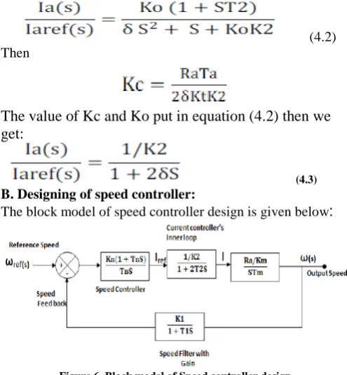
B. Designing of speed controller:
The block model of speed controller design is given below
:
Figure 6. Block model of Speed controller design.
Transfer function of above block model is given as:
To cancels the largest time constant of the transfer function so Tn= 2µδ then, Transfer function of above block model is given as:
In above transfer function, the S term is absent. So that damping constant (€) will be zero. Due to this the system will be oscillatory and unstable. To optimize this we must get transfer function whose gain is close to unity. For this purpose the MODULUS HUGGING APPROCH is used. [2][3][5].
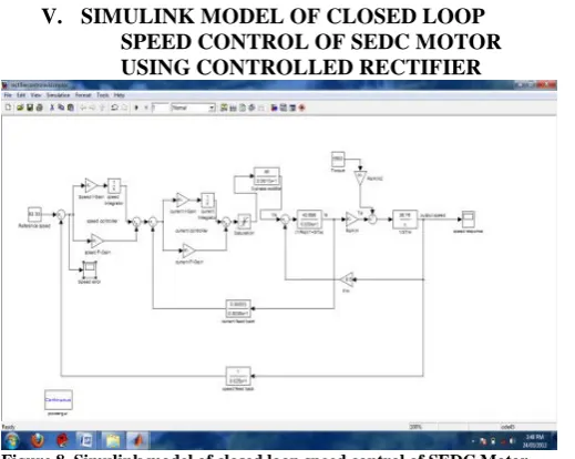
V. SIMULINK MODEL OF CLOSED LOOP SPEED CONTROL OF SEDC MOTOR USING CONTROLLED RECTIFIER
Figure 8. Simulink model of closed loop speed control of SEDC Motor.
VI. SIMULATION RESULTS
The simulation results of different speed and load
torque:
Figure 9. Speed response at rated speed and rated load torque
Figure 10. Error in speed response at rated speed and rated load torque
Figure 11. Speed response at rated speed at half of rated load torque
Figure 12. Error in speed response at rated speed and at half of rated load torque
Figure 13. Speed response at half of rated speed and at rated load torque
Figure 14. Error in speed response at half of rated speed and rated load torque
www.ijiset.com
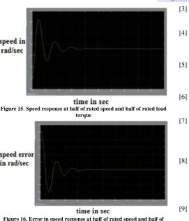
Figure 15. Speed response at half of rated speed and half of rated load torque
Figure 16. Error in speed response at half of rated speed and half of rated load torque
VII.CONCLUSION
This paper presents numerical demonstrating of shut circle speed control of dc engine utilizing three stage controlled rectifier. For stable operation of SEDC engine, the outlining of speed controller is finished utilizing Modulus embracing approach. By this approach the pick-up of framework progresses toward becoming solidarity. The recreation comes about are gotten in the wake of planning of shut circle framework. From the reproduction result we watched that the speed of SEDC engine is consistent at the reference speed which is evaluated or underneath the appraised speed of engine and furthermore watched that the speed blunder is set to be zero. The framework's reaction demonstrates the quick ascent time, quick setting time and additionally quick recuperating time.
REFERENCE
[1] Moleykutty George, Speed Control of Separately Excited DC motor, American Journal of Applied Sciences, 5(3), 227-233, 2008.
[2] Gopakumar K. Power Electronics and Electrical Drives, Video Lectures 1-25, Centre for Electronics and Technology, Indian Institute of Science, Bangalore.
[3] S. Bennett, “Development of the PID Controller,” IEEE Control System Magazine, Dec, 1994, pp.58-65.
[4] Bose B.K., Power electronics and motor drives recent technology advances, Proceedings of the IEEE International Symposium on Industrial Electronics, IEEE, 2002,pp22-25
[5] Fatma GURBUZ, Eyup AKPINAR, ‘Stability Analysis of a Closed-Loop speed Control for a Pulse Width Modulated DC Motor Drive’ Turk J Elect. Engin, VOL.10 No.3 2002.
[6] C.U. Ogbuka, Performance characteristics of Controlled separately excited dc motor, Pacific Journal of Science and Technology, 10(1), 67-74. [7] Zuo Z. Liu,Frang L. Luo, Rashid M.H., High
performance nonlinear MIMO field weakening controller of a separately excited dc motor, Electric Power System research, Vol. 55, Issue 3, 2000, pp(157-164).
[8] Sarat Kumar Sahoo, Ashwin Kumar Sahoo, Razia Sultana, ‘Lab VIEW Based Speed Control of DC Motor using Modulus Hugging Approach’, European Journal of Scientific Research, ISSN 1450-216X Vol.68 No.3 (2012), pp. 367-376©EuroJournals Publishing, Inc. 2012.
[9] Vichupong Vibunjaroen1, Yothin Prempraneerach “Tuning of PI and PID Controller Designed by SO”
PSU-UNS International Conference on Engineering and Environment -ICEE-2007, Phuket May10-11, 2007.
[10] D. Jouve, J. P. Rognon And D. Roye, “Effective Current And Speed Controllers For Permanent Magnet
Machines: A Survey,” Ieee Ch2853-0/90/0000-0384, 1990.
[11] D. Y. Ohm, "Analysis Of Pid And Pdf Compensators For Motion Control Systems," IEEE, IAS Annual Meeting, Pp. 1923-1929, Denver, Oct.2-7, 1994. [12] K. Astrom and T. Hagglund, Pid Controllers: Theory,
Design And Tuning, 2nd Ed., ISA,1994.
[13] R.Krishnan, “Electric Motor Drives Modelling, Analysis, and Control”, Prentice Hall International, Inc., 2001.
[14] Infineon Technologies, Basic DC motor speed PID control with the Infineon Technologies.
[15] Rashid, M.H., Power Electronics, Prentice Hall of India, New Delhi, 1993.
[16] Bimbhra, P.S. Power Electronics, New Delhi, Khanna Publishers, 2006.
[17] Dubey, G.K., Fundamentals of Electrical Drives. New Delhi, Narosa Publishing House, 2009.
[18] Gopal, M., Control Systems, Principles and Design. New Delhi, Tata McGraw Hill Publishing Company limited 2008.
[19] Ogata, K., Modern Control Engineering. Englewood Cliffs, NJ: Prentice Hall, 2001.