Power Line Communication and GSM Based
Electrical Demand Management System for
Asian Countries
Kuruppu KDRS1, Gunathilake KTR2, Subramaniam Thayaparan3
Department of Electrical, Electronic and Telecommunication Engineering, General Sir John Kotelawala Defence
University, Sri Lanka1,2
Department of Electronic and Telecommunication Engineering, University of Moratuwa, Sri Lanka3
ABSTRACT:This paper describes a demand management system based on narrow band Power line communication and GSM technologies which can be used by the electricity provider to reduce electrical load by turning off non-essential equipment in establishments during high demand periods where enough electricity cannot be supplied. This solution is thought to have less impact on the lives of the public. The system uses Blum-Goldwasser cryptosystem for secure power line communication and to mitigate rogue devices. The system does not require internet connectivity. Therefore, ideal for countries with less internet coverage.
KEYWORDS: Demand Management, GSM, Power Line Communication, Public Key Encryption.
I.INTRODUCTION
Power line communication (PLC) is one of the technologies that have proved useful for control applications and it is a system where communication signals can be sent and received on household or industrial current carrying power lines. This concept involves transmitting information using the electrical power distribution network as the communication channel.
The principle of PLC consists of transmitting a high frequency signal at low energy levels over the 50 Hz electrical signal by superimposing a modulated carrier signal on line voltage. This data signal is transmitted via the power line and can be received and decoded at another location in the same electrical network.
PLC based automation systems range from highly complex such as CEBus which uses complex techniques like spread spectrum to simple ones such as X10 [1, 2, 3]. Complex automation systems have higher capabilities that are not neces-sary for a demand management system and have a higher price point due to their complexity. Simple PLC systems such as X10 need further improvement to best suit this application.
In this study we analyzed the available PLC automation systems and research done on electrical demand management to formulate a demand management system by amalgamating a specially designed PLC system with GSM communica-tion.
II.PROBLEM STATEMENT
Apart from a few Asian countries who have implemented demand management systems, most Asian countries rely on load shedding where electricity is not supplied to certain regions in the country at particular time intervals to reduce the demand.This method of demand management causes blackout in those regions which has a highly negative impact on the daily lives of people. To cope with the growing demand for electricity in Asian countries and as most countries are unable to meet their peak demands, a demand management system capable of reducing the overall demand with mini-mum impact on daily lives of people is required.
III.RELATED WORK
Limited number of studies have been done to provide a solution to this problem [6, 7, 8]. [6] gives a load categorization method where high priority places such as hospitals are not used in LS. Even in this method, places which are used for LS completely loses power. Therefore, it does not provide a solution for low priority places such as households. Most of the proposed solutions for this problem are internet based [8]. However, according to world bankopendata website internet availability in Asian countries is limited. In Afghanistan, only around 8% of the population has internet facili-ty. In Asian region as a whole only 50% of the people have internet facilifacili-ty. But when it comes to cellular subscribers, in south Asia, 78.389% of the population have cellular subscriptions. Statistics show that GSM based demand man-agement solution is a better choice for Asian countries.
The paper [7] gives a demand management system based on GSM. In this system, the consumer must manually reduce the electrical load of the building by switching off appliances in order to keep the electrical supply. If the total electrical load of the building surpasses the allowed amount, the whole building loses power. In this solution, the user has to ma-nually turn off appliances until the allowed demand is met. This can be troublesome as the load due to each appliance is hard to be determined. The proposed system utilizes the automation system given in [9] and the system given in [7] as an enforcer to form a demand management system which accomplishes all the above criteria with no hassle to the con-sumer.
IV.SYSTEM ANALYSIS
The proposed system enable consumers to categorize their appliances as: All, Essential and Basic. Where ‘All catego-ry’ is the default; ‘Essential categocatego-ry’ contains few appliances that are essential for daily routines; ‘Basic categocatego-ry’ contains one or two mandatory appliances that are required to maintain important daily activities. Electricity provider can control the demand by dropping the establishments in a certain area into Essential or Basic categories by sending SMSs to Central Control Systems (CCS) of those establishments. All communication between the outside world (i.e. electricity provider etc.) and the house/establishment are carried out in GSM by CCS. Relaying of commands to ap-pliances is done via PLC. This setup does not require internet connectivity.
Each establishment contains a single CCS which houses the message processing unit and the GSM to PLC gateway. Non-essential appliances which may be controlled by the supplier are fitted with PLC Receiver Nodes. Receiver nodes are connected to the CCS via the power lines forming a star topology. The proposed model is a secured one-way com-munication model where only CCS to Node comcom-munication is possible. For this setup two-way comcom-munication is not mandatory. The cost of the system is reduced by utilizing only one-way communication.
4.1. Physical Layer
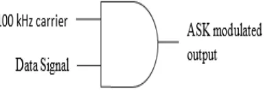
An Amplitude Shift Keying (ASK) modulated 100 kHz carrier is used at the physical layer to transmit data packets. Due to the simplistic nature of ASK, equipment can be made cheaper. An NE555 pulse generator is used to generate the 100 kHz carrier. As shown in Figure 1 an AND Gate (4081 IC) is used to produce the ASK modulated waveform.
In PLC, it is observed that the signal attenuation is low at zero crossings of the 50 Hz AC voltage. To achieve high SNR, the modulated 100 kHz signals are transmitted at the zero crossings of the 50 Hz AC voltage. This gives an ade-quate data rate of 100 bit/s with increased SNR per bit (Eb/N0) which reduces the bit error probability [3].
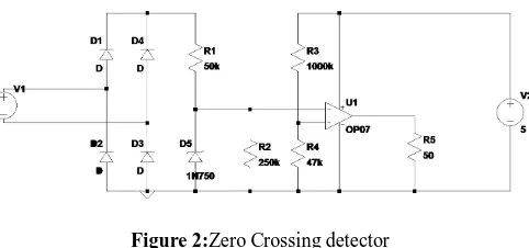
Figure 2:Zero Crossing detector
To transmit and receive bits at the zero crossings, both the transmitter and the receiver must take the input from a zero-crossing detector. Figure 2 shows the Zero Crossing detector which is used in our design. It output pulses when the 230 V 50 Hz AC waveform is within ±5 V.
4.2. Encryption
Most houses have power outlets outside the house for various uses. With PLC comes the risk of an adversary being able to control the inside appliances by plugging a rogue controller to an outside outlet. To overcome this, encryption is used for secure communication. Another reason for encryption is to identify authentic receiver nodes and mitigate third parties from building receiver nodes that perform malicious activities. This is facilitated by maintaining a registered receiver node list in ‘Authorized Nodes Table’ in a central database. All third-party receiver nodes are registered in this database prior to releasing to the market after testing by an authoritative body. Users can be given the option via a web interface/SMS to verify the validity of receiver nodes they buy.
For this application, Blum-Goldwasser (BG) cryptosystem is used, which is a public key cryptosystem and the packet length does not increase after encryption [10]. For a given node, the keystream used for encrypting and decrypting changes only when a new initial seed is selected for BBS pseudo-random generator. Therefore, the encryption process can be optimized by reusing the same keystream to encrypt/decrypt multiple packets without significant risk.
Generating the BBS sequence in the encryption and decryption process, generating the initial seed from the final state of BBS generator and the private key at the receiver require taking modulus of powers and multiplications. Al-though the final result of the modulus has a fixed length, multiplications and powers tend to overflow variables during calculation. To overcome this modulo arithmetic identities such as (1) and (2) were used. Apart from these identities Shrage’s method given in [11] is used.
( × ) = [( ) × ( )] (1)
( + ) = [( ) + ( )] (2)
4.3. Protocol
3 , 3 , 1 , 4 The Even Parity bit is used to detect corrupted packets.
Periodically, a new is selected for each node and a new keystream is generated and cached at the CCS. The result-ing for each node is transmitted using the Update Packets. Receiver will use this new and its private key to find the new and generate the new keystream. This will be cached at the receiver to decrypt subsequent command pack-ets until a new Update Packet arrives. The structure of Update Packet
[0
∶
43]
is given below. Start Code of 101 is used in Update Packets to identify them.3 , 3 , 1 ,
m 32
Random Number is the new .
4.4. Central Control System
CCS is the power line transmitter of the proposed system. It maintains information about the receiver nodes and acts as the gateway between GSM communication and PLC. It processes the commands sent via SMS, create appropriate command packets and transmit them via the power line. CCS consist of a processing unit, GSM module, zero crossing detector, 100 kHz carrier generator, power amplifier and a power line coupling circuit. SIM900A Dual Band GSM/GPRS Mini development board was used as the GSM module in the prototype and AT commands were used to retrieve received SMSs. Arduino was used as the processing unit in the prototype version. Features such as receiving SMSs, transmitting packets via the power line, public key encryption was implemented in this version.
The CCS stores the Name, Device address, Public key, Serial number, Category number of the appliances/nodes in a ‘Local Nodes Table’. Apart from this, CCS is tasked with listening for SMSs and periodically sending update packets to update encryption. Timing is kept using timers available in Arduino. It also contains a ‘Key Stream Cache’ which stores the current encrypting keystreams of each appliance.
In order to turn a particular appliance ON/OFF, first, the CCS consults the Local Nodes Table to get the address of the that appliance. It construct the command packet with command {1, 0, 1, 0} for ON and {0, 1, 0, 1} for OFF. The result-ing packet is encrypted usresult-ing the keystream of the appliance stored in the ‘Key Stream Cache’ and transmitted at the zero crossings.
The processing unit of the CCS takes input
[ ]
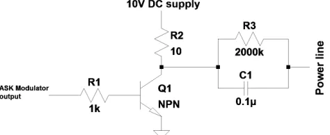
from the zero-crossing detector given in Figure 2. Input is convo-luted as shown in (3) to increase the transmission time of bits and also to neglect any sudden drops to zero within the pulse.Figure 3: Power Amplifier and Coupling Circuit
[ ] =
[ ]. (currenttransmittingbit)
(5)The output signal S[n] is generated as given in (5) and
[ ]
which holds the positive edges of[ ]
and is used to change the transmitting bit to the next bit. Once the last bit it transmitted. The transmission is stopped. The signal[ ]
is fed to the ASK modulator given in Figure 1 and the resulting ASK waveform is given to the circuit in Figure 3 to be power amplified and transmitted to the power line via the coupling circuit. High pass coupling circuit is form by3
and1
which attenuates the 50 Hz waveform by -56 dB but allows the 100 kHz signal to pass with minimum at-tenuation.4.5. Receiver Node
The receiver comprises of a zero-crossing detector shown in Figure 2, coupling circuit, amplifier, envelop detector and a processing unit to implement the protocol. Arduino Uno is used as the processing unit in the receiver.
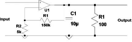
Figure 4: Receiver coupling circuit
Receiver uses the Coupling circuit given in Figure 4 to extract the data signal from the power line where V1 represents the power line. It is a band pass filter with a passband from 60 kHz to 160 kHz. It attenuates the 50 Hz voltage wave-form up to
−
240
and allow the data signal to pass through with almost no attenuation.Figure 5: Receiver Amplifier and Envelop Detector
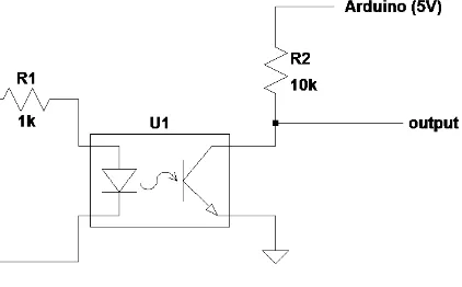
Figure 6:Optocoupler circuit
This circuit is connected to an optocoupler given in Figure 6 which provides optical isolation between the circuit and the processing unit and also further amplifies the signal. The resulting signal
[ ]
and the output of the zero-crossing detector[ ]
are given as inputs to the processing unit.As in the case of the CCS
[ ]
and[ ]
are generated according to (3) and (4). Data[ ]
pulses are also wi-dened similarly to[ ]
by (6) to form[ ]
. Receiver stores the last 47 received bits in a Boolean array .[ ] = [ ]∗( [ ]− [ −200])(6)
Whenever ZCd[n] is HIGH the elements of are shifted to the left according to (7) and the 46th element
[46]
is set as 0. When[ ]
is LOW the last element of the array is changed to the latest bit according to (8).[ −1] = [ ];∀ ∈{ ∈ |0 < < 48}(7)
[47] = [47] + [ ]. [ ](8)
In a decrypted command packet
[0
∶
2]
gives the start code,[12
∶
15]
gives the command etc. Similarly, in an update packet[12
∶
43]
gives the final state of BBS . At the end of a packet three zero bits are sent to notify end of transmission. These three zeros are also used at the receiver along with the start code and the parity to determine a valid packet.V.FUNCTIONAL ANALYSIS
The demand management system requires a central server with a central database with three tables hosted by the elec-tricity provider.
5.1. Authorized Nodes Table
The CCS is fitted by the service provider. Therefore, the authenticity of the CCS is not challenged. However, receiver nodes are bought by the consumer depending on the requirement of appliances. Third party vendors can be allowed to manufacture these separately or incorporate them into their products. This table must be maintained by the electricity supplier to aid in validating receiver nodes and thereby mitigate rogue nodes. It contains records for the receiver nodes authorized by the electricity provider with fields: manufacturer, serial number and public key.
5.2. Customer Details Table
5.3. Device Table
This table contains the details of all the receiver nodes that are connected to the demand management system. It con-tains the house code, node address, public key and the category to which the node belongs. Category is an integer field where 1 = ‘All’, 2 = ‘Essential’ and 3 = ‘Basic’.
5.4. Device Registration Process
In order to add a new appliance to the demand management system, it must be registered in the ‘Device Table’. This is accomplished by sending a ‘Register Device’ SMS in the following format to the electricity provider from the number given in ‘Customer Details Table’.
Central server validates the device by referring to ‘Authorized Nodes Table’. If validated sends a Register Device re-quest to the CCS via SMS. First line of the SMS contains the text “Register Device” and the next line contains the same content of the SMS above. Only ‘Register Device’ messages coming from the electricity provider’s number is processed. This eliminates chances of fraud. The details of the new node is added to the CCS’s node table. This is in-formation is used to automate the devices when changing the mode.
5.5. Mode Change Process
To change the operating mode of a house/establishment the electricity provider sends an SMS to that house’s CCS in the following format:
Only ‘SetCategory’ messages coming from electricity provider’s number are processed. Once received, the CCS identi-fies all the nodes categorized at or below the received category number by querying the ‘Local Nodes Table’ and send turn OFF messages to those nodes.
The load management system described in [7] is used to enforce selective LS. If the demand imposed by the house/establishment surpasses the allowed amount as a result of the consumer disconnecting receiver nodes or due to any other fraudulent activity, the CCS will cut total power and that particular establishment will go to blackout condi-tion.
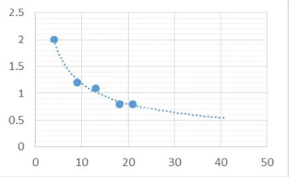
VI. RESULTS AND DISCUSSION
Figure 7 gives the observed variation of signal level (V) with distance. As the receiver can operate with 600 mV signal level, by analyzing the signal variation maximum communication distance can be calculated as 30 m.
VI.CONCLUSION
Thus it allows each node with message to decide whether to copy the message to a path node by optimizing its trans-mission effort in order to provide a sufficient level of message delay. Using a channel selection scheme provides spec-trum utilization while it minimizes the interference level to primary system. Using trustworthy algorithm, itimproves the trustworthiness of the Spectrum sensing in CR-Networks. It enables network nodes to adaptively regulate their communication strategies according to dynamically changing network environment.
REFERENCES
1. M. Shwehdi and A. Khan, “A power line data communication interface using spread spectrum technology in home automation,” IEEE Tran-sac- tions on Power Delivery, vol. 11, no. 3, 1996.
2. S. Sarkar and P. Kundu, “A proposed method of load scheduling and generation control using gsm and plcc technology,” Michael Faraday IET International Summit 2015, 2015.
3. B. Sklar, Digital communications: fundamentals and applications, 2nd ed. Pearson Education, 2001.
4. Jamil, Faisal, “Comparison of Electricity Supply And Tariff Rates In South Asian Countries”, Energy Forum of Sri Lanka. 5. “Smart Grid - The Electricity Grid of Post Fossil Fuel era”, Energy Forum of Sri Lanka.
6. M. Amin, A. Rasheed, A. A. Raja, A. Lateef, S. Khalid, and B. Khan, "Smart-Grid Based Real-Time Load Management Methodology for Power Deficient Systems," International Journal of Electronics and Electrical Engineering, Vol. 3, No. 6, pp. 431-437, 2015.
7. Labib, M. Billah, M. R. Islam and G. M. S. M. Rana, "Design and construction of smart load management system: An effective approach to manage consumer loads during power shortage," 2015 International Conference on Electrical Engineering and Information Communication Technology (ICEEICT), pp. 1-4, 2015.
8. N. Dlodlo, A. Smith, L. Montsi and C. Kruger, "Towards a demand-side smart domestic electrical energy management system," 2013 IST-Africa Conference & Exhibition, pp. 1-12, 2013.
9. KDRS Kuruppu, KTR Gunathilaka, WLPK Wijesinghe and SubramaniamThayaparan, "Power Line Communication for Home Automation in Low Income Households", 3rd International Conference on Power Generation Systems and Renewable Energy Technologies (PGSRET). 10. M. Blum and S.Goldwasser, “An efficient probabilistic public-key encryption scheme which hides all partial information,” Advances in
Cryp-tology Lecture Notes in Computer Science, p. 289299.
11. P. Bratley, B. L. Fox, and L. E. Schrage, A guide to simulation, 2nd ed. Springer-Verlag, 1996.
12. A. Drosopoulos and M. Hatziprokopiou, “Planning and development of lab training activities for powerline communications,” IEEE Transac- tions on Education, vol. 53, no. 3, p. 384389, 2010.
13. H. C. Ferreira, Power line communications: theory and applications for narrowband and broadband communications over power lines. Wiley, 2010.
14. H. Gassara, M. C. Bali, F. Duval, F. Rouissi, and A. Ghazel, “Coupling interface circuit design for experimental characterization of the nar- rowband power line communication channel,” 2012 IEEE International Symposium on Electromagnetic Compatibility, 2012.
15. A. Majumder and J. Caffery, “Power line communications: an overview,” IEEE Potentials, vol. 23, no. 4, p. 413, 2004.
16. R. A. Rashid, M. A. Sarijari, M. R. A. Rahim, and T. Z. Yang, “Flood transmission based protocol for home automation system via power line communication,” 2008 International Conference on Computer and Communication Engineering, 2008.