NDA-24245 ISSUE 2 STOCK # 200890
Hotel Features and Specifications
®
MAY, 2000
LIABILITY DISCLAIMER
The information contained in this document is specific to Dterm Series E only. Throughout this document, references to “Console” or “Attendant Console” imply a Hotel Console. Most features described in this manual require a Hotel Console. However, some features (including A-57, A-73, I-23, P-34, and V-16) can also be performed using a Business Console.
Minimum firmware may be required. Contact NEC Engineering for additional information.
NEC America, Inc. reserves the right to change the specifications, functions, or features, at any time, without notice.
NEC America, Inc. has prepared this document for use by its employees and customers. The information contained herein is the property of NEC America, Inc. and shall not be reproduced without prior written approval from NEC America, Inc.
NEAX and Dterm are registered trademarks of NEC Corporation. Copyright 1998, 1999, 2000
ISSUE 1 ISSUE 2 ISSUE 3 ISSUE 4
DATE DECEMBER, 1998 DATE MAY, 2000 DATE DATE
ISSUE 5 ISSUE 6 ISSUE 7 ISSUE 8
DATE DATE DATE DATE
NEAX2400 IMX
Hotel Features and Specifications
Revision Sheet 1/2NDA-24245 ISSUE 2
PAGE No. ISSUE No.
1 2 3 4 5 6 7 8
i 1 2
ii 1 2
iii 1 2
iv 1 2
v 1 2
vi 1 2
vii 1 2
viii 1 2
1 1 2
2 1 2
3 1 2
4 1 2
5 1 2
6 1 2
7 1 2
8 1 2
9 1 2
10 1 2
11 1 2
12 1 2
13 1 2
14 1 2
15 1 2
16 1 2
17 1 2
18 1 2
19 1 2
20 1 2
21 1 2
22 1 2
23 1 2
24 1 2
25 1 2
26 1 2
27 1 2
28 1 2
29 1 2
30 1 2
31 1 2
32 1 2
33 1 2
34 1 2
35 1 2
36 1 2
37 1 2
38 1 2
39 1 2
40 1 2
41 1 2
42 1 2
43 1 2
44 1 2
45 1 2
46 1 2
47 1 2
48 1 2
49 1 2
50 1 2
51 1 2
52 1 2
53 1 2
54 1 2
55 1 2
56 1 2
57 1 2
58 1 2
59 1 2
60 1 2
61 1 2
62 1 2
63 1 2
64 1 2
65 1 2
66 1 2
67 1 2
68 1 2
PAGE No. ISSUE No.
ISSUE 1 ISSUE 2 ISSUE 3 ISSUE 4
DATE DECEMBER, 1998 DATE MAY, 2000 DATE DATE
ISSUE 5 ISSUE 6 ISSUE 7 ISSUE 8
DATE DATE DATE DATE
NEAX2400 IMX
Hotel Features and Specifications
Revision Sheet 2/2NDA-24245 ISSUE 2
69 1 2
70 1 2
71 1 2
72 1 2
73 1 2
74 1 2
75 1 2
76 1 2
77 1 2
78 1 2
79 1 2
80 1 2
81 1 2
82 1 2
83 1 2
84 1 2
85 1 2
86 1 2
87 1 2
88 1 2
89 1 2
90 1 2
91 1 2
92 1 2
93 1 2
94 1 2
95 1 2
96 1 2
97 1 2
98 1 2
99 1 2
100 1 2
101 1 2
102 1 2
103 1 2
104 1 2
105 1 2
106 1 2
PAGE No. ISSUE No.
1 2 3 4 5 6 7 8
107 1 2
108 1 2
109 1 2
110 1 2
111 1 2
112 1 2
113 1 2
114 1 2
115 1 2
116 1 2
117 1 2
118 1 2
119 1 2
120 1 2
121 1 2
122 1 2
123 1 2
124 1 2
125 1 2
126 1 2
127 1 2
128 1 2
129 1 2
130 1 2
131 1 2
132 1 2
133 1 2
134 1 2
135 1 2
136 1 2
137 1 2
138 1 2
139 1 2
140 1 2
141 1 2
142 1 2
143 2
144 2
PAGE No. ISSUE No.
NDA-24245 ISSUE 2 MAY, 2000
NEAX2400 IMX
Hotel Features and Specifications
Feature List
Page
A-10
Automatic Wake-Up . . . 15
A-10D
Automatic Wake-Up D
term. . . 20
A-15
Announcement Service . . . 26
A-25
Attendant Console With Hotel Functions . . . 27
A-26
Audit Reports . . . 30
A-48
Automatic Message Waiting Lamp Off . . . 32
A-57
Alert Service . . . 33
A-58
Automatic Wake-up – Hotel Attendant . . . 35
A-73
Automatic Multiple Attendant Recall . . . 37
A-74
Answering Camp-On/Call Hold Calls By Switchhook Flash . . . 39
A-75
Automated Guest Station Voice Mail Retrieval . . . 41
B-26
Busy Status – Hotel Attendant . . . 42
C-19
Calendar Display . . . 44
C-23
Check-In/Checkout . . . 45
C-32
Calling Station Number Display . . . 47
C-71
Called Number Display – Hotel Attendant Console . . . 49
C-72
Connecting Room Service . . . 51
C-147
Call Information Display . . . 53
D-11
Do Not Disturb . . . 55
D-11D
Do Not Disturb - D
term. . . 58
D-15
Day/Night Class of Service . . . 60
D-23
Direct Page Connection . . . 61
D-24
Direct Paging . . . 62
D-25
Direct Service Set/Reset . . . 63
D-26
Direct Station Selection . . . 65
D-88
Directory Assistance Interface . . . 66
D-89
Direct Selection – Outside . . . 67
D-105D
D
termWith Hotel Function . . . 68
D-107
Direct Data Entry – Station . . . 73
D-150
Double Suite Room . . . 74
D-151
DND/MW Lamp Control . . . 76
E-21
Emergency Call Monitor – Attendant . . . 77
G-1
Guest/Administrative Service . . . 78
G-4
Group Service Through PMS . . . 79
G-5
Guest Name Display Through PMS . . . 82
G-6D
Guest Name Display – D
term. . . 83
G-7D
Guest Information Display – D
term. . . 87
G-8
Guest Information Display – Hotel Attendant Console . . . 89
Feature List (Continued)
Page
G-11
Guest Room Calling – Hotel Attendant . . . 91
G-21
Group Restriction . . . 93
G-24
Guest Station - D
term. . . 97
H-8
House Phone/Hot Line . . . 98
H-22
Feature Transparency Over CCIS . . . 99
I-23
Inter-Position Transfer 2 . . . 104
L-27
Language Service . . . 105
M-6
Message Waiting . . . 107
M-22
Maid Status . . . 109
M-51
Manual Switching Of C.O. Incoming Call Destination . . . 112
M-68
Maid Status - Answerback . . . 113
O-6
Off-hook Alarm . . . 114
O-9
Overtime Call . . . 115
P-8
Printer Control – Hotel Attendant Console . . . 116
P-27
PMS Interface – BISYNC . . . 117
P-29
PMS Interface . . . 118
P-34
Paging Console . . . 120
R-9
Room Cutoff . . . 121
R-10
Room Status . . . 123
R-17
Room Numbering . . . 124
S-17
Split Access . . . 125
S-32
Screening (Split Hold) . . . 126
S-49
Service Call Routing . . . 127
S-74
Secretarial Service – Guest Station . . . 128
S-75
Suite Room Service . . . 132
S-128
2nd Wake-up Call – Same Guest Station . . . 135
T-13
Toll Terminal Access . . . 139
T-21
Timing Start . . . 140
V-16
Voice Mail Service Via Message Center Interface (MCI) . . . 141
List of Figures
Figure Page
1
Key Allocations of Desk Console . . . 28
2
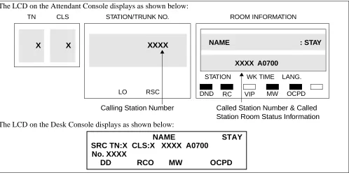
Display Area of Attendant Console and Desk Console . . . 49
3
Console Lamps Used for Connecting Suites . . . 52
4
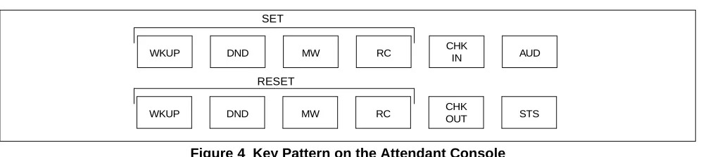
Key Pattern on the Attendant Console . . . 63
5
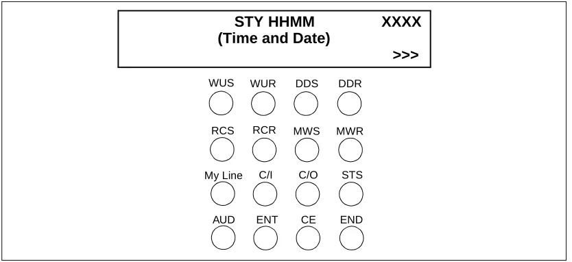
Key Pattern on the Desk Console . . . 63
6
Example of 16-Button D
termon a Front Desk Console. . . 71
7
Example of Single/Double Suite Room . . . 74
8
LCD display on Special Administration Station D
term. . . 83
9
DSS Key/Station Correspondence and Lamp Indications . . . 92
10
Example of Display for Call Origination —
from Attendant Console and Desk Console . . . 99
11
Example of Display for Call Origination from D
term. . . 99
12
Call Termination on Attendant Console, Desk Console,
Special Administration D
term. . . 100
13
Example of Service Feature Setting — Attendant Console
and Desk Console . . . 101
14
Check-In/Checkout Keys Replaced by Secretary
Service Set/Reset (SCS, SCR) . . . 130
List of Tables
Table Page
1
Special Services Requiring Access Numbers . . .
5
2
Example of Dial Access Numbering Plan for Administration Station . . .
6
3
Example of Dial Access Numbering Plan for Guest Station . . .
7
4
Standard Service Abbreviations on D
term. . . 72
NEAX2400 IMX Hotel Features
LEGEND
X – Available
— – Not Applicable N – Not Available
→ → →
→ – Feature carried over to next software series
Index Feature Description
Series 7300 Series 7400
Non-Network FCCS
Non-Network FCCS
A-10 Automatic Wake-Up X X → →
A-10D Automatic Wake-Up Dterm X X → →
A-15 Announcement Service X — → —
A-25 Attendant Console With Hotel Functions X N → N
A-26 Audit Reports X X → →
A-48 Automatic Message Waiting Lamp Off X X → →
A-57 Alert Service X N → N
A-58 Automatic Wake-up – Hotel Attendant X N → →
A-73 Automatic Multiple Attendant Recall X N → N
A-74 Answering Camp-On/Call Hold Calls By Switchhook Flash X — → —
A-75 Automated Guest Station Voice Mail Retrieval X — → —
B-26 Busy Status – Hotel Attendant X X → →
C-19 Calendar Display X — → —
C-23 Check-In/Checkout X X → →
C-32 Calling Station Number Display X X → →
C-71 Called Number Display – Hotel Attendant Console X X → →
C-72 Connecting Room Service X N → N
C-147 Call Information Display X N → N
D-11 Do Not Disturb X X → →
D-11D Do Not Disturb - D
term
Note: Different from Business. X X → →
D-15 Day/Night Class of Service X N → N
D-23 Direct Page Connection X — → —
D-24 Direct Paging X — → —
D-25 Direct Service Set/Reset X X → →
D-26 Direct Station Selection X — → —
D-88 Directory Assistance Interface X N → N
D-89 Direct Selection – Outside X — → —
D-107 Direct Data Entry – Station X N → N
D-150 Double Suite Room X N → N
D-151 DND/MW Lamp Control X X → →
E-21 Emergency Call Monitor – Attendant X N → N
G-1 Guest/Administrative Service X X → →
G-4 Group Service Through PMS X X → →
G-5 Guest Name Display Through PMS X X → →
G-6D Guest Name Display – Dterm X X → →
G-7D Guest Information Display – Dterm N N N N
G-8 Guest Information Display – Hotel Attendant Console X N → N
G-9 Guest Information Display – PMS Terminal X N → N
G-11 Guest Room Calling – Hotel Attendant X X → →
G-21 Group Restriction X N → N
G-24 Guest Station - Dterm X X → →
H-8 House Phone/Hot Line X — → —
H-22 Feature Transparency Over CCIS X — → —
I-23 Inter-Position Transfer 2 X N → N
L-27 Language Service X X → →
M-6 Message Waiting X X → →
M-22 Maid Status X X → →
M-51 Manual Switching Of C.O. Incoming Call Destination X N → N
M-68 Maid Status - Answerback X N → N
O-6 Off-hook Alarm X X → →
O-9 Overtime Call X X → →
P-8 Printer Control – Hotel Attendant Console X X → →
P-27 PMS Interface – BISYNC X X → →
P-29 PMS Interface X X → →
P-34 Paging Console X — → —
R-9 Room Cutoff X X → →
R-10 Room Status X X → →
NEAX2400 IMX Hotel Features (Continued)
LEGEND
X – Available
— – Not Applicable N – Not Available
→ → →
→ – Feature carried over to next software series
Index Feature Description
Series 7300 Series 7400
Non-Network FCCS
R-17 Room Numbering X — → —
S-17 Split Access X X → →
S-32 Screening (Split Hold) X N → N
S-49 Service Call Routing X X → →
S-74 Secretarial Service – Guest Station X N → N
S-75 Suite Room Service X X → N
S-128 2nd Wake-up Call – Same Guest Station X X → →
T-13 Toll Terminal Access X X → →
T-21 Timing Start X X → →
V-16 Voice Mail Service Via Message Center Interface (MCI) X X → →
W-2 Wake-up Announcement – Headstart X N → N
NEAX2400 IMX Hotel Features (Continued)
LEGEND
X – Available
— – Not Applicable N – Not Available
→ → →
→ – Feature carried over to next software series
Index Feature Description
Series 7300 Series 7400
Non-Network FCCS
INTRODUCTION
CHAPTER 1
INTRODUCTION
General Description
This manual covers the Office Data Design of the Hotel System, the Numbering Plan and a description of Service features.
How to Follow the Manual
This manual is organized as follows:
• CHAPTER 2 - NUMBERING PLAN
This chapter explains the numbering plan in the hotel system.
• CHAPTER 3 - DESCRIPTION OF SERVICE FEATURES
NUMBERING PLAN
CHAPTER 2
NUMBERING PLAN
General Description
Access Codes for various service features are determined according to the Dial Access Numbering Plan. This chapter explains the Numbering Plan, and commands related to the Numbering Plan in the Hotel System.
Dial Access Numbers
There are three types of Dial Access Numbers:
• Station Access Numbers
• Special Service Access Numbers
• Trunk Access Numbers
This section explains the procedure for determining these Dial Access numbers and precautions.
Basic Knowledge of Dial Access Numbers
a.) A Dial Access Number consists of an Access Level and a Number of Digits as shown below:
b.) For the Hotel System, the service to be performed is determined according to the specific Dial Access Number.
c.) The Hotel System can have two Numbering Plan Development tables; one is for Administration stations and the other for Guest stations.
Therefore, the Dial Access Number for Administration stations and the Dial Access Number for Guest stations can be provided independently.
Examples:
• Dial Access Number for Administration Station
Dial Access Number Access To
“0” Split Access (Operator Call)
“10” Speed Calling – System
“12” Call Hold
“2XXXX” Guest Station (4 or 5 digits) of Main Building
“3XXXX” Guest Station (4 or 5 digits) of Annex
“4XXX” Administration Station (4 digits)
“5XXX” Special Administration (4 digits)
“8X” 2-Digits Trunk
“9” C.O. Trunk
“6” and “7” Vacant Level
A B C D E F
Dial Access Number:
NUMBERING PLAN
Basic Knowledge of Dial Access Numbers (cont’d)
• Dial Access Number for Guest Station
Note: For the Access Level (1st digit of the Dial Access numbers) different numbers are assigned for Station Access numbers, Special Service Access numbers, and Trunk Access numbers.
Station Access Numbers
a.) One through six-digit station numbers are supported.
b.) The system can provide Timing Start Service. The Timing Start Service allows single-digit and multi-digit stations to use the same Access levels.
Examples:
2101: Guest Station Number of No. 1 Room on the 1st floor of the main building. 21001: Guest Station Number of No. 1 Room on the 10th floor of the main building. 3101: Guest Station Number of No. 1 Room on the 1st floor of the annex.
31001: Guest Station Number of No. 1 Room on the 10th floor of the annex.
c.) The same station number cannot be assigned twice within the same system, even if it is assigned to different tenants or to an Administration Station and a Guest Station.
Special Service Access Numbers
a.) Special Service Access numbers of one through six digits can be assigned for each Access Level. Usually, one through three digits are used.
b.) The Hotel System can provide the Same Number Access (Split Access) service.
The Same Number Access service can provide both Administration and Guest stations with the different service feature by the same number.
It can also provide the same or a different service feature by the same number according to Tenant Class, Route Restriction Class (RSC) and Service Feature Class (SFC) concerned.
Examples:
c.) The Hotel System can provide the Floor Service. The Floor Service is a service function to call the Room Service station on each floor by the same Access code.
Dial Access Number Access To
“0” Split Access (Special Administration Station (STN 5000) Call
“13” Automatic Wake Up; Set
“14” Automatic Wake Up; Cancel
“2XXXX” Guest Station (4 or 5 digits) of Main Building
“3XXXX” Guest Station (4 or 5 digits) of Annex
“7” Floor Service
“9” C.O. Trunk
“4”, “5”, “6”, and “8” Vacant Level
Dial Code Service Feature for Administration
Station Service Feature for Guest Station
NUMBERING PLAN
Special Service Access Numbers (cont’d)
Examples:
Guest Station on the 1st Floor of the main building dial “7” Calling
→ Room Service Station (STN 4801) on the 1F Guest Station on the 2nd Floor of the main building
dial “7”
→ Calling Room Service Station (STN 4802) on the 2F Guest Station on the 3rd Floor of the main building
dial “7”
→ Calling Room Service Station (STN 4803) on the 3F
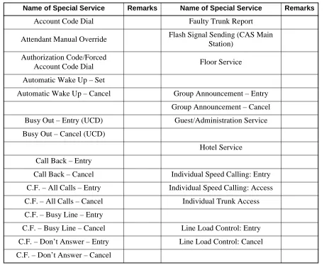
d.) Table 2-1 shows a listing of special services which require Access numbers.
Note: In a case where both Entry and Cancel are specified for the same special service, different Access numbers must be assigned for Entry and for Cancel.
Trunk Access Numbers
a.) Trunk Access numbers ranging from one through six (1-6) digits may be assigned on an individual basis. Usually, one through three (1-3) digits are used.
Table 1 Special Services Requiring Access Numbers
Name of Special Service Remarks Name of Special Service Remarks
Account Code Dial Faulty Trunk Report
Attendant Manual Override Flash Signal Sending (CAS Main
Station)
Authorization Code/Forced
Account Code Dial Floor Service
Automatic Wake Up – Set
Automatic Wake Up – Cancel Group Announcement – Entry
Group Announcement – Cancel
Busy Out – Entry (UCD) Guest/Administration Service
Busy Out – Cancel (UCD)
Hotel Service
Call Back – Entry
Call Back – Cancel Individual Speed Calling: Entry
C.F. – All Calls – Entry Individual Speed Calling: Access
C.F. – All Calls – Cancel Individual Trunk Access
C.F. – Busy Line – Entry
C.F. – Busy Line – Cancel Line Load Control: Entry
C.F. – Don’t Answer – Entry Line Load Control: Cancel
NUMBERING PLAN
a.) Trunk Access numbers are required on an individual route basis.
b.) When Least Cost Routing (LCR) is utilized, LCR Access is regarded as access to an individual route; therefore an Access Number must be assigned.
c.) If Answer Service is provided for Speaker and/or Radio Paging, a Paging Answer code must be assigned.
Examples of a Dial Access Numbering Plans are shown in Table 2, Example of Dial Access Numbering Plan for Administration Station and Table 3, Example of Dial Access Numbering Plan for Guest Station.
Call Hold Message Reminder
Call Park Access Code
Call Park Local Retrieval Code Priority Call 1
Call Park Remote Retrieval Code Priority Call 2
Call Pickup Priority Call 3
Call Pickup – Direct Priority Paging
Call Waiting
Speed Calling Access
Data Privacy – Entry Same Number Access
Data Privacy – Cancel
Dial Access to Attendant TAS Answer
Trunk Queuing: Entry
Executive Right-of-Way Trunk Queuing: Cancel
Voice Call
Table 2 Example of Dial Access Numbering Plan for Administration Station
Access Number Function Remarks
0 Same Number Access (Dial Access to Attendant) Operator Call
10 Call Hold
11 Call Back (Entry) Cancel Number is “19”
12 Executive Right of Way
13 Speed Calling System
14
Vacant Numbers 15
16
17
18
Table 1 Special Services Requiring Access Numbers (Continued)
NUMBERING PLAN
19 Call Back (Cancel) Entry Number is “11”
2000 – 2018 4-digit Administration Station Number
3000 – 3011 4-digit Guest Station Number
4
Vacant Numbers 5
6
7
80 Vacant Numbers
81 Access to Area A Route Number: 2
82 Access to Area B Route Number: 3
83 Access to Area C Route Number: 4
84 Access to Area D Route Number: 5
85 Access to Area E Route Number: 6
86
Vacant Numbers 87
88 Access to Paging Equipment Route Number: 10
89 Vacant Number
9 Access to Central Office Route Number: 1
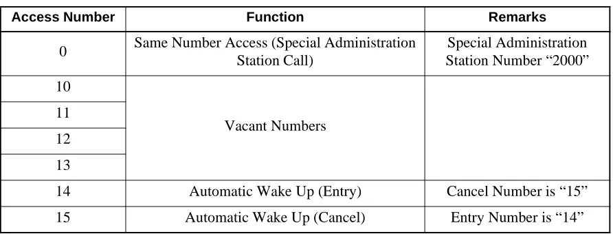
Table 3 Example of Dial Access Numbering Plan for Guest Station
Access Number Function Remarks
0 Same Number Access (Special Administration Station Call)
Special Administration Station Number “2000”
10
Vacant Numbers 11
12
13
14 Automatic Wake Up (Entry) Cancel Number is “15”
15 Automatic Wake Up (Cancel) Entry Number is “14”
Table 2 Example of Dial Access Numbering Plan for Administration Station (Continued)
NUMBERING PLAN
Commands Related to the Numbering Plan
This section explains the commands related to the Numbering Plan and also explains command assignment procedure.
For details of command, refer to the NEAX2400 IMX Office Data Specification Manual. 1. ASYD (Assignment of System Data)
The system data pertaining to the Numbering Plan is as follows:
• SYS1 INDEX 160 b6
This data is for determining whether the Numbering Plan Development Table is to be provided in common or separately for Administration and Guest stations. The commands to be used vary with the value assigned to the data as follows:
a.) When the Table is to be provided in common for Administration and Guest stations. (b6 = 1)
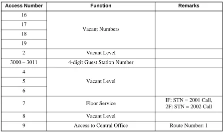
16
Vacant Numbers 17
18
19
2 Vacant Level
3000 – 3011 4-digit Guest Station Number
4
Vacant Level 5
6
7 Floor Service IF: STN = 2001 Call,
2F: STN = 2002 Call
8 Vacant Level
9 Access to Central Office Route Number: 1
Table 3 Example of Dial Access Numbering Plan for Guest Station (Continued)
Access Number Function Remarks
AANP AASP ASPS (Common)
(Common) (Common)
ASPF (Common)
NUMBERING PLAN
Commands Related to the Numbering Plan (cont’d)
b.) When the Table is to be provided separately for Administration and Guest stations. (b6 = 0)
Note: Administration stations can call Guest stations, but calls from Guest stations to Administration stations are restricted. A call from a Guest Station to a predetermined Administration Station is allowed via Same Number Access (Split Access) service.
• SYS1 INDEX 161 b6, b7
b6: “#” code is used in Timing Start Service. (0/1 = Ineffective/Effective)
b7: “*” code is used in Timing Start Service. (0/1 = Ineffective/Effective)
When Timing Start is used, the system can have the following numbering:
Examples:
Floor Room No. Station No.
1st 11 8111
11th 11 81111
In this case, if a 5-digit station number is dialed, the call is immediately connected to the called station. However, if a 4-digit station number is dialed, the call is connected to the called station with a certain delay. This is because the necessary number of digits of the access level assigned by the AANP/AGNP command is set to the number of digits of station number of larger number of digits. Thus, when a station number of smaller number of digits is dialed, the call is not connected to the called station until the Register Inter-Digit Timer in the system is timed out. In order that a call by dialing a station number of smaller number of digits can be immediately connected to the called station, assignment of these system data is necessary. If use of “#” code is made effective, a call to a station of smaller number of digits is connected immediately to the called station with “#” code dialed after the station number. 2. AANP/AGNP (Assignment of Administration Numbering Plan/Assignment of Guest Numbering Plan)
These commands are used to assign the minimum required number of digits to be used for determining the required service according to the first digit received.
Note: When the Timing start service is used, the minimum required number of digits is assigned to the station number of larger number of digits.
For example, when Station Number 200 and Station Number 2000 exist, Number of Necessary Digits (NND) = 4 is to be assigned with respect to the 1st Digit (1st DC) = 2.
3. A dummy number (SID36, STATE 63) is necessary for the following case: When the system has stations “200” and “21000”, assign a dummy number for “210” with NND = 2.
4. AASP/AGSP (Assignment of Administration Special Access Code/Assignment of Guest Special Access Code)
These commands are used to specify the kind of service to be executed or the route to be accessed when a Special Access Code or Trunk Access Code is dialed. This data pertains to Administration stations.
AANP AASP ASPS (Common)
(for Admin.) (for Admin.)
ASPF (Common) AAST
(for Admin.)
AGNP AGSP
(for Guest) (for Guest) AGST
NUMBERING PLAN
Commands Related to the Numbering Plan (cont’d)
5. ASPS (Assignment of Special Access Code for Same Number Access)
When Split Access (Same Number Access) is required, these commands are used to specify the kind of service to be executed or the route to be accessed when a Special Access Code or Trunk Access Code is dialed.
6. ASPF (Assignment of Special Access Code for Floor Service)
This command is used to assign the calls from Guest stations on each floor, and can be terminated to a service station, such as laundry service and room service, on the same floor as the Guest Station.
7. AAST/AGST (Assignment of Administration Station Data/Assignment of Guest Station Data)
These commands are used to assign station data. When the system provides the floor service, these commands are used to assign floor service data with respect to Guest Room Service Station.
Examples of Numbering Plan Data Assignments
Examples of Numbering Plan data assignments are shown below. The procedures for data assignment are explained in the subsequent pages.
Example:
1. Dial Access Number
• For Administration
Access Code Access To
“0” Operator Call
“100” ~ “1000” Guest Station on 1F “200” ~ “2000” Guest Station on 2F
“3000” ~ “3500” Administration Station Number
“4000” Special Administration Station
“5000” Room Service Station for 1F
“5001” Room Service Station for 2F
“9” C.O. Trunk
• For Guest
Access Code Access To
“0” Special Administration Station Call
“100” ~ “1000” Guest Station on 1F “200” ~ “2000” Guest Station on 2F
“8” Floor Service
“9” C.O. Trunk
2. Others
• Numbering Plan Development Table is provided separately for Administration and Guest.
NUMBERING PLAN
Examples of Numbering Plan Data Assignments (cont’d)
Entry Procedure:
START
ASYD
AANP
SYS1 INDEX 160, b6 = 0
Numbering Plan Development Table is provided separately for Administration and Guest.
INDEX 161, b6 = 0
Use of “#” code in the Timing Start Service is made effective.
INDEX 165, b7 = 1 Floor Service is provided.
With respect to the 1st digit code (1ST DC), assign Number of Necessary Digits (NND) as follows.
1ST DC NND 0 1 1 4
2 4
3 4
4 4 5 4 9 1
With respect to the 1st digit code (1ST DC), assign Number of Necessary Digits (NND) as follows.
1ST DC NND 0 1 1 4 2 4 8 1 9 1
With respect to the Access Code (ACC) assign service features as follows.
ACC SRV SID No. KIND
0 SSC 57 0 0
ACC SRV RT
9 OGC 1
AGNP
A
NUMBERING PLAN
Examples of Numbering Plan Data Assignments (cont’d)
AGSP
ASPS
With respect to the Access Code (ACC) assign service features as follows:
ACC SRV SID No. KIND
0 SSC 57 0 0
8 SSC 56 0 –
ACC SRV RT
9 OGC 1
With respect to the data assigned by AASP and AGSP, assign service features as follows:
No. F SRV SID STN
0 0 SSC 2 –
0 1 STN – 4000
Assign the station data of Administration stations. Also, assign the data for floor service as follows:
STN ROOM CLASS
“3000” ~ “3500” 0
“4000” 0
“5000” 1 – 7
“5001” 1 – 7
Assign the station data of Guest stations. (STN “100” – “1000”, STN “200” – “2000”)
Assign the data related to the Room Service. Station on each floor as follows:
No. ANX G FLR DC
0 0 0 1 5000
0 0 0 2 5001
AAST
AGST
ASPF
END
DESCRIPTION OF SERVICE FEATURES
CHAPTER 3
DESCRIPTION OF SERVICE FEATURES
Hotel Service Features
This section explains each Hotel service feature by the following items:
• General Description
• Operating Procedure
• Service Conditions
General Description
This item explains a general description of the service feature.
Operating Procedure
This item explains the procedure to be followed for receiving a specific service feature concerned. When testing a service feature, perform installation test work steps by referring to this item.
Service Conditions
Automatic Wake-Up A-10
A-10 Automatic
Wake-Up
General Description
This service feature allows the system to be programmed to automatically call guest rooms at specified times. Upon answering, the guest is connected to a recorded announcement or music source. A printout of unanswered or blocked wake-up attempts for guest rooms is provided at the Hotel printer. This feature can be activated from the guest room stations, administration stations, Console, PMS Terminal, or predetermined Special Administration Station.
Operating Procedure
• To set AUTOMATIC WAKE-UP from a guest room:
a.) With separate set and cancel codes (24-hour time only):
b.) When set and cancel codes are the same:
• To cancel AUTOMATIC WAKE-UP from Guest Room:
a.) With separate set and cancel codes (24-hour time only):
b.) When set and cancel codes are the same:
Step Action Result
1 Lift the handset. Receive dial tone.
2 Dial WAKE-UP code. Hear special dial tone.
3 Dial desired time of AUTOMATIC WAKE-UP. Hear service set tone.
4 Hang up.
Step Action Result
1 Lift the handset. Receive dial tone.
2 Dial WAKE-UP code. Hear special dial tone.
3 Dial desired time of AUTOMATIC WAKE-UP. Hear service set tone.
4 Hang up.
Step Action Result
1 Lift the handset. Receive dial tone.
2 Dial CANCEL AUTOMATIC WAKE-UP code. Hear service dial tone.
3 Hang up.
Step Action Result
1 Lift the handset. Receive dial tone.
2 Dial WAKE-UP code. Hear special dial tone.
3 Dial the digit “3”. Hear service set tone.
A-10 Automatic Wake-Up
Operating Procedure (cont’d)
• To set AUTOMATIC WAKE-UP from a Regular Administration Station:
Only separate set and cancel codes will operate from a regular administration station.
• To cancel AUTOMATIC WAKE-UP from a Regular Administration Station: Only separate set and cancel codes will operate from a regular administration station.
• To set AUTOMATIC WAKE-UP from a Special Administration Station:
Only separate set and cancel codes will operate from a special Administration station.
• To cancel AUTOMATIC WAKE-UP from a Special Administration Station:
• To set AUTOMATIC WAKE-UP from the Front Desk Terminal or Console using the WUS/WUR (Wake-Up Set/ Wake-Up Reset) key:
a.) When guest calls to request a wake-up call (see DIRECT SERVICE SET/RESET [D-25]):
Step Action Result
1 Lift the handset. Receive dial tone.
2 Dial SET WAKE-UP code. Hear special dial tone.
3 Dial desired time of AUTOMATIC WAKE-UP. Hear service set tone.
4 Hang up.
Step Action Result
1 Lift the handset. Receive dial tone.
2 Dial CANCEL WAKE-UP code. Hear service set tone.
3 Hang up.
Step Action Result
1 Lift the handset. Receive dial tone.
2 Dial SET WAKE-UP code. Hear special dial tone.
3 Dial desired time of AUTOMATIC WAKE-UP, then
dial the guest room number. Hear service set tone.
4 Hang up.
Step Action Result
1 Lift the handset. Receive dial tone.
2 Dial CANCEL WAKE-UP code and guest room
number. Hear service set tone.
3 Hang up.
Step Action Result
1 Press the WUS key while still connected with the guest room.
Automatic Wake-Up A-10
Operating Procedure (cont’d)
b.) If the wake-up time is entered after the guest line is released:
• To cancel AUTOMATIC WAKE-UP from the Front Desk Terminal or Console using the WUS/WUR (Wake-Up Set/Wake-Up Reset) key:
a.) When guest calls to cancel a wake-up call (see DIRECT SERVICE SET/RESET [D-25]):
b.) If the wake-up cancel is input after the guest line is released:
• To call the guest station that does not answer the wake-up call, from the Console.
Step Action Result
1 Press WUS key. The associated lamp lights.
2 Dial wake-up time. The console displays the entered time.
3 Dial the guest station number. The console displays the station number.
4 Press the ENTER key. The lamp flashes to confirm that AUTOMATIC
WAKE-UP has been set.
5 Press the EXIT key. The lamp and station display are extinguished.
Step Action Result
1 Press the WUR key while still connected with the guest room.
Step Action Result
1 Press WUR key. The associated lamp lights.
2 Dial guest station number. The console displays the station number and the AUTOMATIC WAKE-UP time set.
3 Press the ENTER key. The lamp flashes to confirm the cancellation of
the wake-up call.
4 Press the EXIT key. The lamp and station display are extinguished.
Step Action Result
1 The guest does not answer the wake-up call. The call is routed to Attendant and terminates on the WU key.
2
Press the WU key or ANSWER key. The following is displayed:
3 Press the START key. The guest station is rung.
4 If the guest does not answer, release the call by pressing CANCL key.
The guest number is given to the front desk clerk and he/she is asked to visit the guest room.
HH:MM NAME :NANS DEST TN:X CLS:X XXXX
No. XXXX
A-10 Automatic Wake-Up
Service Conditions
1. From the Front Desk Terminal or Console, set AUTOMATIC WAKE-UP using either 24-hour time, or 12-hour time. When using 12-hour time, time is entered by dialing a special code, which includes either a # or * before entering the time to indicate PM. For example, when dialing the desired time, dial #1030 for 10:30 PM. The choice of # or * is assigned in system data.
2. The maximum number of stations that can set the same wake-up time can be assigned as one of the following: 64, 128, 256, 512 stations per Local Processor (LP). If the number of stations reaches the assigned maximum stations, the next attempt to set an AUTOMATIC WAKE-UP call at the same wake-up time is automatically set 5 minutes earlier than the appointed time.
Note 1:The ability to process this expanded number of calls is based on traffic and station distribution in the system.
Note 2:Variable timing can be assigned in system data. The timing must be a multiple of five minutes (such as 5, 10, or 15) earlier.
3. All AUTOMATIC WAKE-UP times are to be set at five-minute intervals in either 12- or 24-hour time.
Example: 7:50 AM = 0750
7:55 AM = 0755 8:00 AM = 0800
Note: Wake-Up Time to be set from a station/Console will be rounded to the nearest multiple of five.
4. If a Wake-Up announcement is used, this feature requires one of the following hardware alternatives: a.) Central Office Trunk (COT) or 2W E&M trunk and an announcement machine.
b.) Digital Announcement Trunk (DAT).
5. This feature provides three additional AUTOMATIC WAKE-UP attempts at fixed three-minute intervals. If the called party is not reached (i.e., no answer, busy, blocked, or locked-out) after a total of four attempts, the results will be automatically printed out at the hotel printer. The number of retries for a no-answer condition is determined by system data, up to a maximum of three retries. The number of retries for a busy condition is flexible, up to a maximum of three retries.
6. Ringing duration for AUTOMATIC WAKE-UP is controlled by the CF/NA timer, SYS1, ASYD, INDEX 139. The choice of ring duration is made through programming in system data.
7. AUTOMATIC WAKE-UP overrides DO NOT DISTURB [D-11].
8. AUTOMATIC WAKE-UP messages can be arranged for headstart operation. Refer to the WAKE-UP ANNOUNCEMENT – HEADSTART [W-2] feature description for details.
9. If WAKE-UP ANNOUNCEMENT – HEADSTART [W-2] is not required, announcements can be arranged either as continuous recordings (last party disconnects) or to automatically disconnect after 30 seconds. An engineering traffic study is required to determine the number of interface trunks needed to accommodate each recording channel.
10. AUTOMATIC WAKE-UP for a guest station can be set from the Console, predetermined Special Administration stations, Front Desk Terminal, or the actual guest phone. AUTOMATIC WAKE-UP for an Administration Station can only be set from the actual administration phone.
Note: Any Administration Station that is assigned as a Special Administration Terminal may NOT set WAKE-UP for itself or for any station other than a guest station.
11. If PMS Language Selection is used, AUTOMATIC WAKE-UP announcements can be provided according to a guest's language.
12. If all announcement trunks are busy, music will be provided for AUTOMATIC WAKE-UP. Music is provided by the NEAX2400 IMX MUSIC ON HOLD [M-1] source.
Time to be set by keypad operation is Time to be set by system is
xx: x1 ~ xx: x4 xx: x0
Automatic Wake-Up A-10
Service Conditions (cont’d)
13. For guest stations, a confirmation announcement can be provided instead of service set tone for AUTOMATIC WAKE-UP setting and cancelling operations.
14. AUTOMATIC WAKE-UP entry and result information is reported, as required, to the PMS and NEAX2400 IMX hotel printer for continuous update.
15. A maximum of six digits can be used for the identification code. Use of an ID code is not mandatory, and is left to the customer's discretion.
16. It is possible to use the same access code for both AUTOMATIC WAKE-UP set and cancel. For example: *1 may be assigned the AUTOMATIC WAKE-UP set and cancel access code. The system will recognize *1 and wait for the next digit. If *, #, 0, 1, or 2 is dialed, then a time is being set. If 3 is dialed, this is an AUTOMATIC WAKE-UP cancel.
Example:
*1 *0300 3:00 PM wake-up set (12-hour clock)
*1 #0300 3:00 PM wake-up set (12-hour clock)
*1 0800 8:00 AM wake-up set (12/24-hour clock)
*1 1000 10:00 AM wake-up set (12/24-hour clock)
*1 2100 9:00 PM wake-up set (24-hour clock)
*1 3 Wake-up cancel
17. As a system option, once AUTOMATIC WAKE-UP has been set from a guest station, only that guest station is allowed to cancel or change the WAKE-UP service. This option is determined by system data (Wake-Up Guest Station Priority Service).
18. These same conditions are applicable to WAKE-UP ANNOUNCEMENT – HEAD START [W-2]. 19. Setting and cancelling wake-up services may be restricted, depending on service class, from
Administration Stations, the PMS Terminal, a Front Desk Terminal, or predetermined Special Administration Stations.
20. When AUTOMATIC WAKE-UP for a guest station is set from the Console, the PMS Terminal, a Front Desk Terminal, or predetermined Special Administration Stations, that guest station is allowed to set/ cancel the WAKE-UP service.
21. When AUTOMATIC WAKE-UP has been executed, setting/cancelling of another AUTOMATIC WAKE-UP service is allowed from the Console, the PMS Terminal, a Front Desk Terminal, or predetermined Special Administration Stations.
22. AUTOMATIC WAKE-UP [A-10] and WAKE-UP ANNOUNCEMENT-HEADSTART [W-2]
procedures remain the same.
23. Maximum number of stations per LP that can be set for a single AUTOMATIC WAKE-UP time is determined by the system data.
24. The system can be programmed so that, once a day, the system will generate and print a Wake-Up report listing all Wake-Ups that are currently set. The time of the output is decided by the customer and assigned in the AHSY Command.
A-10D Automatic Wake-Up Dterm
A-10D Automatic
Wake-Up
D
term
General Description
This service feature allows the system to be programmed to automatically call guest rooms at specified times. Upon answering, the guest is connected to a recorded announcement or music source. A printout of unanswered, blocked, or busy wake-up attempts for guest rooms is provided at the Hotel printer. This feature can be activated from the guest room Dterms.
Operating Procedure
• To set AUTOMATIC WAKE-UP from a guest room Dterm (24-hour time only): a.) With separate set and cancel codes:
Step Action Result
1 Lift the handset or press the SPKR key. Receive dial tone.
2 Dial WAKE-UP code.
Hear special dial tone. The LCD displays:
3 Dial desired time of AUTOMATIC WAKE-UP.
Hear service set tone. The LCD displays:
4 Hang up.
If the AUTOMATIC WAKE-UP time steady display is available by system data, the following will display:
WAKE UP SET (Time and Date)
>>>
XX:XX SET (Time and Date)
>>>
XX:XX
(Time and Date)
Automatic Wake-Up Dterm A-10D
Operating Procedure (cont’d)
b.) When set and cancel codes are the same:
• To cancel AUTOMATIC WAKE-UP from a guest room Dterm (24-hour time only): a.) With separate set and cancel codes:
b.) When set and cancel codes are the same:
Step Action Result
1 Lift the handset or press the SPKR key. Receive dial tone.
2 Dial WAKE-UP code.
Hear Special Dial Tone.
3 Dial desired time of AUTOMATIC WAKE-UP.
Hear service set tone. The LCD displays:
4 Hang up.
If the AUTOMATIC WAKE-UP time steady display is available by system data, the following will display:
Step Action Result
1 Lift the handset or press the SPKR key. Receive dial tone.
2 Dial CANCEL AUTOMATIC
WAKE-UP code.
Hear service set tone. The LCD displays:
3 Hang up.
Step Action Result
1 Lift the handset or press the SPKR key. Receive dial tone.
2 Dial WAKE-UP code. Hear special dial tone.
3 Dial the digit “3”.
Hear service set tone. The LCD displays:
4 Hang up.
WAKE UP SET (Time and Date)
>>>
XX:XX SET (Time and Date)
>>>
XX:XX
(Time and Date)
>>>
WAKE UP CNCL (Time and Date)
>>>
WAKE UP CNCL (Time and Date)
A-10D Automatic Wake-Up Dterm
Service Conditions
1. From the guest room Dterm, set AUTOMATIC WAKE-UP using 24-hour time only. 2. When AUTOMATIC WAKE-UP is executed, the LCD will display:
3. When the Dterm answers the wake-up call, “WAKE UP” display will remain.
4. The maximum number of stations that can set the same wake-up time can be assigned as one of the following: 64, 128, 256, 512 stations per LP (Local Partition) depending on System Data programming. If the number of stations reaches the assigned maximum stations, the next attempt to set an AUTOMATIC WAKE-UP call at the same wake-up time is automatically set 5 minutes earlier than the appointed time.
Note 1:The ability to process this expanded number of calls is based on traffic and station distribution in the system.
Note 2:Variable timing can be assigned in system data. The timing must be a multiple of five minutes (such as 5, 10, or 15 minutes) earlier.
5. All AUTOMATIC WAKE-UP times are to be set at five-minute intervals.
Example:
7:50 AM = 0750 7:55 AM = 0755 8:00 AM = 0800 3:00 PM = 1500 3:55 PM = 1555
Note: Wake-Up Time set from a station will be rounded to the nearest multiple of five.
6. If Wake-Up announcement is used, this feature requires one of the following hardware alternatives: a.) Central Office Trunk (COT) or 2W E&M trunk and an announcement machine.
b.) Digital Announcement Trunk (DAT).
7. This feature provides three additional AUTOMATIC WAKE-UP attempts at fixed three-minute intervals. If the called party is not reached (i.e., no answer, busy, blocked, or locked-out) after a total of four attempts, the results will automatically print out at the hotel printer. The number of retries for a no-answer or busy condition is determined by system data, up to a maximum of three retries.
8. Ringing duration for AUTOMATIC WAKE-UP is controlled by SYS1, ASYD, INDEX 139, the Call Forward, No Answer timer.
9. AUTOMATIC WAKE-UP overrides DO NOT DISTURB [D-11].
10. AUTOMATIC WAKE-UP messages can be arranged for headstart operation. Refer to the WAKE-UP ANNOUNCEMENT – HEADSTART [W-2] feature description for details.
11. If WAKE-UP ANNOUNCEMENT – HEADSTART [W-2] is not required, announcements can be arranged either as continuous recordings (last party disconnects) or to automatically disconnect after 30 seconds. An engineering traffic study is required to determine the number of interface trunks needed to accommodate each recording channel.
Time to be set by keypad operation Time to be set by system
xx:x1 ~ xx:x4 xx:x0
xx:x6 ~ xx:x9 xx:x5
WAKE UP (Time and Date)
Automatic Wake-Up Dterm A-10D
Service Conditions (cont’d)
12. When AUTOMATIC WAKE-UP is set from the Administration Station, Front Desk Terminal, or Console, the LED for AUTOMATIC WAKE-UP on the guest room Dterm illuminates. If the AUTOMATIC WAKE-UP time steady display is available, the following will display:
13. If PMS Language Selection is used, AUTOMATIC WAKE-UP announcements can be provided according to a guest’s language.
14. If all announcement trunks are busy, music will be provided for AUTOMATIC WAKE-UP. Music is provided by the NEAX2400 IMX MUSIC ON HOLD [M-1] source.
15. For guest stations, a confirmation announcement can be provided instead of service set tone for AUTOMATIC WAKE-UP setting and cancelling operations.
16. AUTOMATIC WAKE-UP entry and result information is reported, as required, to the PMS and NEAX2400 IMX hotel printer for continuous update.
17. A maximum of six digits can be used for the identification code. Use of an ID code is not mandatory, and is left to the customer’s discretion.
18. It is possible to use the same access code for both AUTOMATIC WAKE-UP set and cancel. For example, *1 may be assigned the AUTOMATIC WAKE-UP set and cancel access code. The system will recognize *1 and wait for the next digit. If 0, 1, or 2 is dialed, then a time is being set. If the 3 is dialed, this is an AUTOMATIC WAKE-UP cancel.
Example:
*1 0800 8:00 AM wake-up set
*1 1000 10:00 AM wake-up set
*1 2100 9:00 PM wake-up set
*1 3 wake-up cancel
19. As a system option, once AUTOMATIC WAKE-UP has been set from a guest station, only that guest station is allowed to cancel or change the WAKE-UP service. This option is determined by system data (Wake-Up Guest Station Priority Service).
20. These same conditions are applicable to WAKE-UP ANNOUNCEMENT – HEADSTART [W-2].
21. AUTOMATIC WAKE-UP [A-10] and WAKE-UP ANNOUNCEMENT – HEADSTART [W-2]
procedures remain the same.
22. For Distinctive Ringing of AUTOMATIC WAKE-UP, C.O. Line Incoming Connection is used.
23. When several services are set at the same time, services are displayed according to the following order of priority:
1. AUTOMATIC WAKE-UP - Dterm [A-10D]
2. 2ND WAKEUP CALL – SAME GUEST STATION [S-128]
3. MESSAGE WAITING [M-6]
4. DO NOT DISTURB - Dterm [D-11D]
5. ROOM CUTOFF [R-9]
24. AUTOMATIC WAKEUP is not activated for the guest station which has been set DO NOT DISTURB -Dterm by using the DND key of a Dterm Series E.
XX:XX
(Time and Date)
A-10D Automatic Wake-Up Dterm
Service Conditions (cont’d)
Example:
a.) When setting DO NOT DISTURB – Dterm only:
b.) When setting DO NOT DISTURB – Dterm and AUTOMATIC WAKE-UP – Dterm:
c.) When setting DO NOT DISTURB – Dterm, AUTOMATIC WAKE-UP – Dterm and MESSAGE WAITING:
d.) When setting DO NOT DISTURB – Dterm, AUTOMATIC WAKE-UP – Dterm, MESSAGE WAITING and 2ND WAKEUP CALL – SAME GUEST STATION (MW lamp illuminates):
In case of the MESSAGE WAITING lower display (MW lamp illuminates):
Note: On the upper LCD, AUTOMATIC WAKE-UP - Dterm, 2ND WAKE-UP CALL - SAME GUEST STATION, DO NOT DISTURB - Dterm, and ROOM CUTOFF are displayed in order of priority.
DD
(Time and Date)
>>> Lamp A Lamp B Lamp C Lamp D
Lit
XX:XX DD (Time and Date)
>>> Wake-Up Time
Lamp A Lamp B Lamp C Lamp D
Lit Lit
XX:XX DD MW (Time and Date)
>>> Lamp A Lamp B Lamp C Lamp D
Wake-Up Time
Lit Lit Lit
XX:XX YY:YY MW
(Time and Date)
>>> Lamp A Lamp B Lamp C Lamp D Wake-Up Time Second Wake-Up Time
Lit Lit Flashing
XX:XX YY:YY DD (Time and Date)
>>> Lamp A Lamp B Lamp C Lamp D
Automatic Wake-Up Dterm A-10D
Service Conditions (cont’d)
e.) When setting DO NOT DISTURB – Dterm, AUTOMATIC WAKE-UP – Dterm, MESSAGE WAITING, 2ND WAKEUP CALL – SAME GUEST STATION and ROOM CUTOFF (the MW lamp illuminates):
f.) When going on-hook at the status of “e” after AUTOMATIC WAKE-UP – Dterm is activated (the MW lamp illuminates):
g.) When cancelling 2ND WAKEUP CALL – SAME GUEST STATION at the status “e” (the MW lamp illuminates):
25. Maximum number of stations per LP that can be set for a single AUTOMATIC WAKE-UP time is determined by the system data.
Lamp A Lamp B Lamp C Lamp D XX:XX YY:YY MW (Time and Date)
>>> Wake-Up Time Second Wake-Up Time
Lit Lit Lit Flashing
YY:YY DD RC MW
(Time and Date)
>>> Lamp A Lamp B Lamp C Lamp D
Second Wake-Up Time
Lit Lit Lit Lit
XX:XX DD RC MW
(Time and Date)
>>> Lamp A Lamp B Lamp C Lamp D
Wake-Up Time
A-15 Announcement Service
A-15 Announcement
Service
General Description
This service feature allows a station user to hear a prerecorded announcement for various services such as:
ALERT SERVICE [A-57]
AUTOMATIC WAKE-UP [A-10]
Confirmation announcement (See AUTOMATIC WAKE-UP) [A-10]
DO NOT DISTURB [D-11] mode setting
GROUP SERVICE THROUGH PMS [G-4]
Hotel information
Intercept announcement when a vacant level is dialed
Language selection (Property Management System (PMS) option)
Restricted call attempts (ROOM CUTOFF) [R-9]
Tourist group information (tour group schedule & agenda)
Operating Procedure
• To access:
Service Conditions
1. This feature requires one of the following hardware alternatives:
a.) Central Office Trunk (COT) or 2W E&M trunk and an announcement machine. b.) Digital Announcement Trunk (DAT).
2. Announcements can be arranged as continuous recordings (last-party disconnect) or to automatically disconnect after 30 seconds. An engineering traffic study is required to determine the number of interface trunks needed to accommodate each recording channel.
3. If PMS Language Selection is utilized, ANNOUNCEMENT SERVICE can be provided according to guest’s language.
4. The following connections are available:
a.) Multi-connection - many station users can connect to one announcement trunk at the same time. b.) Single connection - one station user can connect to one announcement trunk at the same time 5. This feature is also available for the Tie Line trunk access to announcement trunk.
6. The system can be programmed to return Ring Back Tone before connection to the announcement machine is made.
7. When this feature is activated from a Tie Line, the system can be programmed to return answer supervision to far-end PBX.
8. If PMS Language Selection is used, Announcement Service can be provided according to the guest’s language.
9. Checked out Guest Stations cannot use this feature, except for Room Cutoff Announcement.
Step Action Result
1 Lift the handset or press the SPKR key. Receive dial tone.
2 Dial the associated announcement service access code.
The NEAX2400 IMX responds with an announcement.
Attendant Console With Hotel Functions A-25
A-25
Attendant Console With Hotel Functions
General Description
The NEAX2400 IMX Console provides regular business call handling and processing capabilities, as well as hospitality functions. The console provides for the following special hospitality services:
1. Individual keys to set and reset:
AUTOMATIC WAKE-UP [A-10]
MESSAGE WAITING [M-6]
CHECK-IN/CHECKOUT [C-23]
DO NOT DISTURB [D-11]
SECRETARIAL SERVICE – GUEST STATION [S-74]
ROOM STATUS [R-10]
MANUAL SWITCHING OF C.O. INCOMING CALL DESTINATION [M-51]
ROOM CUTOFF [R-9]
AUDIT REPORT [A-26] (requires a hotel
printer) 2. Special keys for incoming call identification:
ADM – Incoming administrative calls
DND – Incoming calls to stations in DO NOT DISTURB [D-11] mode EMG – OFF HOOK ALARM [O-6] – Emergency calls (option) GST – Incoming guest station calls
GST2 – Incoming foreign guest station calls (option) HP – HOUSE PHONE/HOT LINE [H-8]
OT – Overtime calls (option)
WU – Wake-Up calls (option) (Morning Call [MC])
3. Direct key access to frequently called Administration or service stations (i.e., room service, restaurant, maid, or C.O. number). These numbers are preassigned via the MAT. Ten keys are provided for this function.
4. The console provides the following displays: Calendar (date and time)
Call Waiting (number of calls) Class of Service
Name Display - System (for Administration stations) Room Status:
– AUTOMATIC WAKE-UP [A-10]
– DO NOT DISTURB [D-11]
– GUEST NAME DISPLAY THROUGH PMS [G-5]
– Language (PMS Option)
– MESSAGE WAITING [M-6]
– Optional data display (Refer to Service Condition 3.) – Room class
– ROOM CUTOFF [R-9]
A-25 Attendant Console With Hotel Functions
General Description (cont’d)
Note: If the Desk Console is used instead of the NEAX2400 IMX Hotel Attendant Console, the basic key allocations are different from the previous ones. The following illustration shows the Desk Console key positions and indications used in hotel system. The operating procedures for each service are the same as the NEAX2400 IMX Hotel Attendant Console.
Figure 1 Key Allocations of Desk Console
Operating Procedure
Refer to the NEAX2400 IMX How to Operate Attendant Console.
Service Conditions
1. Distance limitation between the NEAX2400 IMX and the console: up to 1000 feet (304 meters) using 25-pair, 24 AWG cable.
2. Maximum of four consoles per PIM.
3. A three-character and a five-character display can be used in conjunction with PMS to display additional guest information instead of language and room class. For example, company name, complementary code, etc. may be displayed.
TRKSL SVC SC
DDO
WUS
WUR DDR RCR MWR STS DDS RCS MWS HWS BV MR CLR TG1 TG6 TG7 TG8 TG9 TG10 TG5 TG4 TG3 TG2 Enter Clear Exit
L 6 L 5 L 4 L 3 L 2 L 1
1 2 ABC DEF3
6 MNO 5 JKL 4 GHI 9 WXYZ 8 TUV 7 PQRS # ∗ 0 Cancel Talk SRC Answer DEST Release Hold Position Busy Position Busy Night Night PAGE REC Start Mute TF Recall NANS ADM Busy TIE LDN Alarm Position Available
HWC HP DD GST OT ICPT
LCD
DSS key
Hotel Function key
The different key indications of the NEAX2400 IMX Attendant Console and the newer Desk Console are shown below:
Hotel Attendant
Console Desk Console
WKUP (Set) WKUP (Reset) DND (Set) DND (Reset) RC (Set) RC (Reset) MW (Set) MW (Reset) WUS WUR DDS DDR RCS RCR MWS MWR Hotel Attendant
Console Desk Console
Attendant Console With Hotel Functions A-25
Service Conditions (cont’d)
A-26 Audit Reports
A-26 Audit
Reports
General Description
The System provides AUDIT REPORT printout of all rooms assigned specific Room Status conditions. For example, an AUDIT of all stations in DO NOT DISTURB [D-11] mode may be ordered. These REPORTS are generated by key operation and function codes entered from the Hotel Console. AUDIT REPORTS available from the printer are as follows:
Function
Printout Information
Code Definition
0 All Status All Status
1
Maid Status
To be Cleaned
2 Cleaned
3 Ready to sell
4 Out of Service
5 Repair Needed
6 Vacant
7
Room Condition
Occupied
8 MESSAGE WAITING set [M-6]
9 AUTOMATIC WAKE-UP [A-10] (Room & Time)
10 Vip Room (see service condition, PMS option)
11 DO NOT DISTURB [D-11]
12 ROOM CUTOFF [R-9]
*
Room Class
All Class Audit
21 Room Class 1
22 Room Class 2
23 Room Class 3
24 Room Class 4
25 Room Class 5
26 Room Class 6
27 Room Class 7
28 Room Class 8
29 Room Class 9
20 Room Class 10
2* Room Class 11
Audit Reports A-26
Operating Procedure
• To order AUDIT REPORTS printouts from the Console or Front Desk Terminal:
Service Conditions
1. VIP classification must be entered via PMS. 2. Room classifications are assigned via the MAT.
3. Guest name and optional data (Language, etc.) are displayed on the Console, but are not included in the printout.
4. Hotel printer is necessary for this service feature. 5. Only one audit may be run at a time.
6. Status information is automatically printed out when the following services are performed: • MAID STATUS [M22] (from guest room only).
• AUTOMATIC WAKE-UP [A-10] (unanswered, blocked calls).
Step Action Result
1 Press the AUD key. The associated lamp illuminates
2 Press the STS key.
3 Dial the desired function code. The function code is displayed.
A-48 Automatic Message Waiting Lamp Off
A-48
Automatic Message Waiting Lamp Off
General Description
This feature provides for guest station MESSAGE WAITING [M-6] lamps to automatically turn off after guests have called predetermined Administration Stations (i.e. Message Center) to retrieve messages.
Operating Procedure
When a guest calls the Administration Station to retrieve a message, the MESSAGE WAITING [M-6] lamp on the associated guest telephone is automatically extinguished and the MESSAGE WAITING [M-6] data is cleared.
Service Conditions
1. This service is only available when the MESSAGE WAITING [M-6] has been set from: a.) Front Desk Terminal (Model 90 or 120 PMS).
b.) Front Desk Terminal or Console (Model 60 PMS). 2. This feature is not available when calling the Console.
3. Message Waiting lamps set by Message Center Interface will not be canceled by AUTOMATIC MESSAGE WAITING LAMP OFF [A-48].
Alert Service A-57
A-57 Alert
Service
General Description
In an emergency situation, the Console or Special Administration Station may initiate the ALERT SERVICE. All guest stations and Special Administration Stations are called, using a distinctive ringing pattern, and connected to an emergency announcement.
At this time, if Dterms are used for guest stations, the Dterm LCDs will indicate emergency.
Operating Procedure
• To set ALERT SERVICE from Console:
• To cancel ALERT SERVICE from Console:
• To set ALERT SERVICE from Special Administration Station:
• To cancel ALERT SERVICE from Special Administration Station:
• To answer:
Step Action Result
1 Press the LOOP key.
2 Dial the access code for Alert Service Setting.
• Receive Service Set Tone.
• All the Guest Stations and all the Special Administration are rung.
3 Press the RELEASE key.
Step Action Result
1 Press the LOOP key.
2 Dial the access code for Alert Service Cancel. Receive Service Set Tone.
3 Press the RELEASE key.
Step Action Result
1 Lift the handset. Receive Dial Tone.
2 Dial the access code for Alert Service Setting.
• Receive Service Set Tone.
• All the Guest Station and all the Special Administration Station are rung.
3 Replace the handset.
Step Action Result
1 Lift the handset. Receive Dial Tone.
2 Dial the access code for Alert Service Cancel. Receive Service Set Tone.
3 Replace the handset.
Step Action Result
1 The Stations rung by the Alert Service lifts the handset.
Announcement is heard from the Announcement Machine. (Note)
A-57 Alert Service
Operating Procedure (cont’d)
Note: On answering, the station is automatically connected to an announcement machine. If Language service has been specified by PMS, the guest will receive the announcement in their own language.
Service Conditions
1. A guest station is called every 2 seconds, to a maximum of 24 stations per Module Group ringing simultaneously. The stations are called in ascending order, based on Line Equipment Number (LEN) per Module Group (MG). After all stations in a Port Interface Module (PIM) have been called, the process is repeated in an attempt to reach stations that did not answer, were busy, or were blocked. Unreached stations will be tried three times by the system.
2. Stations will be retried if the guest does not answer, the line is busy, or the line is in LINE LOCKOUT [L-3]. Stations in the Make Busy condition are not called. This information is reported to the hotel printer. 3. ALERT SERVICE overrides DO NOT DISTURB [D-11].
4. Special Administration Stations are also called.
5. The ringing pattern used with ALERT SERVICE is shown below. This pattern may not be changed.
6. If a printout of responses (i.e., answered, blocked, busy) is required, the hotel printer must support a minimum of 220 characters per second (CPS).
7. When announcement trunks for ALERT SERVICE in different languages are provided, the guest receives the announcement in his/her own language. In this case, the guests are connected to the announcement trunk in multiple connection, and if the guest does not go on hook after hearing the announcement, the call is disconnected automatically after 30 seconds.
8. While guest stations are ringing, the LCDs on the guest room Dterms (if used) will display: ON
OFF
0.2 sec
0.4 sec
1 sec 0.2 sec
0.4 sec 0.4 sec
0.4 sec
EMERGENCY CALL