Conductor less Bus Ticketing System Using RFID and
Accident Information through GPS and GSM
P
1
P
T.Manikandan, P
2
P
G.Kalaiyarasi, P
3
P
K.Priyadharshini, P
4 P R.Priyanga P 1 P
Assistant Professor/ECE P
2 P Assistant Professor/ECE P 34 P
B.E.Final year Department of Electronics and Communication Engineering, JAY SHRIRAM GROUP OF INSTITUTIONS, Tirupur.
Abstract-The objective of this project is to count the passenger using IR sensor and calculating the distance
travelled by passenger automatically using motor and u-slot sensor, and the corresponding amount is debited from RFID card. In addition to that, in proposal system the occurrence of accident information is automatically transmitted to the nearest hospital using GSM and GPS. In IR transmitter and receiver, IR transmitter is nothing but one type of LED, generally called IR transmitter. Initially IR transmitter and receiver are placed straight to each other, so the transmitted IR ray are received by IR receiver. But when passenger crosses the IR transmitter and receiver, the rays received will be interrupted. Here the micro controller used is Atmel 89C52, is flash type reprogrammable memory in which we have already programmed. So, signals received from SCU and increment the count value. Here RFID tag is rechargeable one, where as it can be recharged in bus depot or nearest retail shop. Micro controlled, keypad and LCD are provided in bus depot for recharging purpose by own.
Keyword- MC, IR module, LCD, GSM, GPS, Keypad, Motor and U slot, RFID reader, vibrating sensor.
1. INTRODUCTION
In this paper “GPS based automatic bus fare collecting system using electronic Ticket” explained that a system that uses the same RFID-based location information give the navigation indications depending on his current location; provided that the user has indicated beforehand the places he intends to visit[1]. Collected data can be used to predict bus moment timing in order to provide better service [2]. By using smart card instead of RFID with GPS, we can find the location of the passenger enter and exit [3]. Using the location we can find the distance travelled and amount. The amount can be withdrawn from the smart card. A microcontroller can be used to program this system by interfacing GPS and smart card. By implementing this system the usage of loose cash can be reduced and efficient ticketing can be implemented.
1.1
Existing System
In the general way, every bus is controlled by a conductor. The conductor will collect money from each passenger and issue ticket. Initially, printed papers or tokens are used as tickets. Nowadays, handheld machines are used to print tickets.
This system has many disadvantages. The passenger have to carry the ticket till the end of travel, the conductor should ensure that everyone has got the ticket, [3]the time taken for ticketing is comparatively more and more amount of paper is needed to print the Ticket. Nowadays conductors are trained to operate the handheld ticketing machine.
For example, if a passenger wish to travel in bus. He has to carry money with him. Then conductor will collect the money and he will give ticket. This has to repeat for all passengers. This will take more time and waste of human resource as well as energy. Even handheld ticketing machine is comparatively slow and need trained person to operate it.
In Existing system RFID Reader is used to read the RFID tag but destination should be entered by passenger in keyboard , So that amount will be debited automatically from the tag. Here if once destination is arrived, bus stops automatically and intimate with buzzer sound. Fairly such arrangement consumes more time
access is developed in this proposal with addition of application to transfer information about accident occurrence.
2. PROPOSED METHODOLOGY
GPS is the latest technology used in various fields such as navigation [4], tracking and also in some of surveillance applications. Here we are going to use this GPS to calculate the distance travelled by the passenger. GPS module can configured to generate the latitude and longitude of the current position of the bus. The position of the bus can be monitored continuously using this GPS module. Smart cards can provide identification, authentication, data storage and application processing [5].These smart cards can be used as passenger identifications. Every passenger carries a smart card. The smart card has the information such as user identification number, available balance and status register [7]. These smart cards should be capable of recharging, so that the passenger can use it again and again. Combining GPS technology and smart cards we can design a complete bus ticketing system [6].
Ticketing system without human resource-Conductor is implemented using RFID tag which is rechargeable one. Accident information is intimated to nearest hospital, where as nearest hospital is detected using GPS and information transformation is done with the help of GSM Module. Fig.1 shows the architectural diagram of proposed method.
2.1 ARCHITECTURE
Figure .1-Architecture of Proposed Method
In this architecture, the UART are used to establish serial communications between the GPS module and smart card reader and microcontroller.
Ticketing system:
RF (Radio Frequency) communication occurs by the transference of data over electromagnetic
waves. By generating a specific electromagnetic wave at the source, its effect can be noticed at the receiver far from the source, which then identifies it and thus the information. Initially RFID tag read by RFID reader, so EM waves is in contact and distance calculation is powered automatically amount is reduced when EM waves get uncontact. GPS module has many configurations. For each configuration it will transmit different data such as time, date, latitude position, longitude position, velocity etc. Here it is enough to extract time and date for ticketing. Smart card should have enough memory space for storing the passenger details.LCD display is used to display the available amount in RFID tag passenger, who are travelling.
IR TX/RX VIBRATING
SENSOR
U SLOT RFID
GPS
MICRO CONTROLLER
GSM LCD
MO TOR
Detecting system:
For detecting, we have use the same module GPS for personalizing the latitude and longitude positions for detecting the nearest hospital.GSM is used to send the message to hospital about accident occurrence.
2.2 PROBLEM FINDING:
Hardware debugging is the major problem. We fabricated all the components in PCB and test power supply; input and output, if the ports are not working then check the code and rework in hardware.
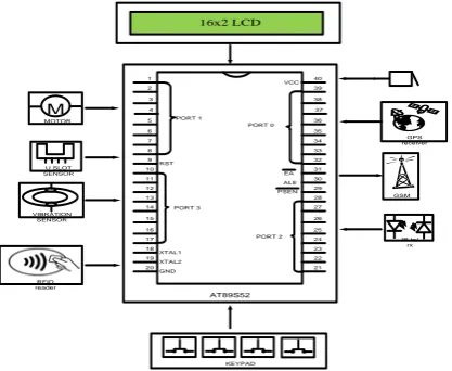
2.3 BLOCK DIAGRAM
1 2 3 4 5 6 7 8 RST 9 10 11 12 13 14 15 16 17 XTAL1 18 XTAL2 19 GND 20 VCC 40 39 38 37 36 35 34 33 32 EA 31 ALE 30 PSEN 29 28 27 26 25 24 23 22 21 PORT 1 PORT 0 PORT 3 AT89S52 PORT 2 16x2 LCD GSM VIBRATION SENSOR U SLOT SENSOR M MOTOR IR tx/ rx GPS receiver RFID reader KEYPAD
Figure .2- Block Diagram of Proposed Method
8-bit Microcontroller with 4K Bytes Flash:
The AT89C51 is a low-power, high-performance CMOS 8-bit microcomputer with 4K bytes of Flash programmable and erasable read only memory (PEROM). The device is manufactured using Atmel’s high-density non-volatile memory technology and is compatible with the industry-standard MCS-51 instruction set. The Idle Mode stops the CPU while allowing the RAM, timer/counters, serial port and interrupt system to continue functioning. The Power-down Mode saves the RAM contents but freezes the oscillator disabling all other chip functions until the next hardware reset.
GPS:
The Global Positioning System is a space age navigational system that can pinpoint your position anywhere on the globe. Automobile manufacturers are also offering moving-map displays guided by GPS receivers as an option on new vehicles, for use in planning a trip. GPS receiver received vehicle position latitude and longitude from satellite through GPS antenna. GPS receiver is interfaced with the microcontroller through RS232 converter.
GSM:
GSM networks operate in a number of different frequency ranges (separated into 31TGSM frequency ranges31T
for 2G and 31TUMTSfrequency bands31T for 3G). Most 31T2G31T GSM networks operate in the 900 MHz or 1800 MHz
bands. GSM-900 uses 890–915 MHz to send information from the 31Tmobile station31T to the 31Tbase station31T (uplink)
spaced at 200 kHz.
RFID SYSTEM:
Radio frequency identification (RFID) is wirelessly, using radio waves. In an RFID system, the RFID tag which contains the tagged data of the object generates a signal containing the respective information which is read by the RFID reader, which then may pass this information to a processor for processing the obtained information for that particular application. An RFID reader consists of an antenna, transceiver and decoder, which sends periodic signals to inquire about any tag in vicinity. On receiving any signal from a tag it passes on that information to the data processor. These tags can be either active or passive. While the active tags have on-chip power, passive tags use the power induced by the magnetic field of the RFID reader. Thus passive tags are cheaper but with lower range (<10mts) and more sensitive to regulatory and environmental constraints, as compared to active tags.
40T
IR transmitter and Receiver:
In IR transmitter and receiver, IR transmitter is nothing but one type of LED, generally called IR transmitter. Initially IR transmitter and receiver is placed straight to each other, so the transmitted IR ray are received by IR receiver. But when passenger crosses the IR transmitter and receiver, the rays received will be interrupted. This infrared transmitter and receiver is called as IR TX-RX pair and cost less than 10RS.
40T
IR LED and IR sensor:
IR LED is used as a source of infrared rays. It comes in two packages 3mm or 5mm. 3mm is better as it is requires less space. IR sensor is nothing but a diode, which is sensitive for infrared radiation.
40T
Figure.3-Model of 3mm and 5mm IR LED
VIBRATION SENSOR (PIEZOELECTRIC SENSOR):
A piezoelectric sensor is a device that uses the piezoelectric effect to measure pressure, acceleration, strain or force by converting them to an electrical signal.
LIQUID CRYSTAL DISPLAY (LCD):
Liquid crystal displays (LCD’s) have materials, which combine the properties of both liquids and crystals. These modules can be interfaced with a 4-bit or 8-bit microprocessor /Micro controller. The LCDs used exclusively in watches, calculators and measuring instruments are the simple seven-segment displays.
BUZZER
A buzzer or beeper is a signalling device, usually electronic, typically used in automobiles, household appliances such as a microwave oven, or game shows.
40T
3. DEVELOPMENT PROJECT
40T
Before go for a project, let us have glance on EMBEDDED SYSTEM because our project based on embedded system.
40T
3.1 EMBEDDED SYSTEM
40T
Embedded system is the combination of Hardware and Software design to perform some dedicated function. Embedded systems are part of a larger system or product, e.g. antilock braking system in car. Here program is embedded into Hardware to perform particular function.
40T
3.2 APPLICATION
40T
In real time, embedded system play an important role. Some examples are:
• 40TAutomotive- Engine control, braking system.
• 40TConsumer devices- toys/games, camera.
• 40TIndustrial control- Robotics.
• 40TMedical- dialysis machine, cardiac monitor.
• 40THome appliances- microwave oven, washing machine.
40T
3.3 TYPES OF EMBEDDED SYSTEM
40T
Embedded system is broadly classified into two, they are: • 40TStandalone embedded system
• 40TNetworking embedded system
40T
3.4 CHARACTERISTICS
• 40TThread switch
• 40TReal time scheduling policy
• 40TResponse to external interrupt quickly
• 40TMinimum interval during, interrupts are disable.
• 40TMaintain real time clock.
• 40TData at fast rate.
40T
4. PROPOSAL METHOD AND WORKING
Ticketing system without human resource-Conductor is implemented using RFID tag which is rechargeable one. Accident information is intimated to nearest hospital, where as nearest hospital is detected using GPS and information transformation is done with the help of GSM Module.
4.1 WORKING
In fare collection system, there are three modes
• Admin mode • User mode • Auto mode
Admin mode
When admin mode is selected, three options will be displayed
• Distance
< 50km
> 50km • Tag number • Recharge user card
User mode
When enter into the bus, select the destination by showing the digital ticket. So bus will stop in responsible stop automatically and intimate with buzzer sound.
Auto mode
When this mode is selected, fare will be collected automatically by distance calculation. Here distance is calculated when passenger get out of bus without any swiping operation done when exit.
Selection of mode:
• In our project, admin mode is used in bus depot for recharging purpose.
• Auto mode is used in bus for automatic fare collection using distance calculation.
4.2 TESTING
First stage: Testing of software
We choose microcontroller because it support peripheral and support hardware, since it is considered has main heart of part. Here not only the software, hardware also play an main role in this project.
• MC AT89C51
• IR TX/RX
• RFID TAG /READER • DC MOTOR
• U-SLOT
• LCD
• GSM MODULE • GPS MODULE
This project is initiated with micro controller. We select AT89C51, because it is more than enough to fulfil the requirements. At the same time, we will start working in programming in AT89C51 in embedded c language. To develop the program,use keil c software, which help us to develop and compile the program and also save the program.
40T
Figure.4-Model of proposed system
32 I/O 33 I/O 34 I/O 35 I/O 36 I/O 37 I/O 38 I/O
Input and Output Pins (I/O) For Buzzer
28 I/O
Input and output pins (I/O) For Keypad
12 I/O 13 I/O 14 I/O 15 I/O
Input and output pins(I/O) For U-SLOT
3 I/O
Input and output pins(I/O) For MAX-232
• GSM • RFID Reader
32 I/O 33 I/O 34 I/O 35 I/O 36 I/O 37 I/O 38 I/O
Input and Output Pins (I/O) For Buzzer
28 I/O
Input and output pins(I/O) For Keypad
12 I/O 13 I/O 14 I/O 15 I/O
Input and output pins(I/O) For U-SLOT
3 I/O
Input and output pins(I/O) For MAX-232
• GSM • RFID Reader
Second stage: Testing of Hardware
AT89C51 PIN used in the Project :
Input and Output Pins (I/O):
• 4X4 Key Pad • Buzzer
• DC Motor (12v)
• GSM
• GPS
• Relay driver
• Mode selection Relay • U-SLOT
• IR Tx/Rx • LCD(16x2)
Input and Output Pins (I/O) For 16x2 LCD:
39 I/O
40T
5 Result and Conclusion:
By implementing this project as real time project, many disadvantage in ticketing system is rectified and the implementation of sending accident occurrence information automatically to the nearest hospital may save many life. Fare is debited from RFID tag where tag is rechargeable one. But, this Process can made better by imple40Tmenting 40Tthe rechargeable RFID tag as ATM card (or) debit card just by changing the program. So, will
directly debit amount from bank.
40T
6. REFERENCES
:40T
[1] Arul Das.s.v.k.lingeswaran,”GPS Based Automated Public Transport Fare Collection Systems Based On Distance Travelled By Passenger Using Smart Card.
40T
[2] 40TSuresh Sankaranarayanan, Paul Hamilton (2014). “Mobile Enabled Bus Tracking and Ticketing System”,
IEEE trans, Vol.13(9), pp.768-775.
[3] Ana Aguiar, et al “Personal Navigator for a public transport system using RFID ticketing”.
[4] Bernard Menezes1, et al “Challenges in RFID Deployment – A Case in public transportation”.
[5] Bo Yan, Danya Lee, 2009, “Design of Sight Spot Ticket Management System Based on RFID”, International conference.
[6] George Roussos, Vassiliskostakos, “RFID in Pervasive Computing: State- of –the-art and outlook”.
[7] Karaiskos, Dimitrios, et al “User Acceptance of Pervasive Information Systems: Evaluating an RFID Ticketing system”.
[8] Maria Grazia Gnoni, et al , 2009 “A Smart Model for Urban Ticketing Based On RFID Application”, IEEM09-P-0572,IEEE.
[9] Venugopalprasanth, et al, 2009, “Ticketing Solution for Indian Railways Using RFID Technology”, International conference Advances in Computing control and tele communication technologies, 2009, pp.217-219.
40T
BIOGRAPHY
:1.Mr.T.Manikandan post graduated in Applied electronics has completed in the year of 2013 at SSN college of Engineering,Tamilnadu and under graduated in B.E-Electronics and Communication Engineering in the year of 2010 at Institute Road and Transport Technology at Erode. He has published more than 7 national and
international papers.
2.Ms.K.Priyadharshini pursuing B.E Electronics and Communication Engineering at Jay Shriram Group of Institutions,Tirupur.
3.Ms.R.Priyanga pursuing B.E Electronics and Communication Engineering at Jay Shriram Group of Institutions,Tirupur.