ASIC Implementation of MLDD for Error
Detection and Correction
Aabitha Nasrin.J 1, Aarthy.M 2, Asika Mumtaj.M 3, Indhu.S 4, Kalaiselvi.S 5
U.G. Student, Department of Electronics Engineering, Dr.MCET College, Pollachi, Tamil Nadu, India1,2,3,4 Assistant Professor, Department of Electronics Engineering, Dr.MCET College, Pollachi, Tamil Nadu, India5
ABSTRACT: A small transition delays and little faults create major concern in digital circuits. It produces greater impact on not only for simple memory but also for most of the memory applications. During encoding and decoding process, the error may occur in the code word which results in mismatching or loss of information. Error detection and correction are main issues in the memory which needs to be identified and corrected. The proposed method will identify and correct the error in memory application using Majority Logic Decoder and Detector (MLDD). MLDD corrects the error based on number of parity check equations. This method reduces the N-iteration to three iterations, if the code word doesn’t contain any fault. It reduces the memory access time when there is no fault in data read. However it reduces the decoding time that increase memory application. Therefore delay is reduced. The proposed system is designed using structural VHDL code and simulated using Modelsim SE 6.3f and synthesized using Cadence Encounter.
KEYWORDS: Majority Logic Decoder and Detector, Parity check equations, Memory.
I. INTRODUCTION
The impact of technology scaling-smaller dimensions, higher integration densities, and lower operating voltages has come to a level that reliability of memories is put into jeopardy, not only in extreme radiation environments like spacecraft and avionics electronics, but also at normal terrestrial environments [9].Data is most important for any digital system.
The data bits may change from its original value to some other value i.e. a bit containing ‘1’ or ‘0’ changes to ‘0’ or ‘1’ respectively and such change in value is called error. Error in data can occur results in poor accuracy thus making it unreliable. It is caused due to the transmission channel noise or in the memory in which it is stored.
Data is usually transmitted from one place to another. It is sent through the channel which may be an electrical wire or simply an air medium. The fluctuations in electrical signal or any disturbing factor in the air medium causes change in the bit value forming an unreliable data. These fluctuations or disturbing factor are called channel noise. Due to this channel noise the data which is received by the receiver will be different from the data transmitted. Such change in the data causes incorrect computation results. For example: If the sign bit of data is changed then signed data becomes unsigned data or vice versa. In space craft industry even a single bit change is not acceptable. In medical field changes in critical body parameter need high accuracy where error in data is highly intolerable.
When data is stored in memory, errors are introduced by a defect, either the mistake in design or construction, or broken components it can lead to system crashes or alter the answer to an important calculation. The impact of technology scaling-smaller dimensions, higher integration densities, and lower operating voltages has led to increased memory failures.
When some part of a memory chip actually fails, the result is a hard error. Initially, the hard error may appear to be a soft error (i.e., a memory glitch) however, rebooting the system does not alleviate the symptom and possibly the system will not reboot if it cannot pass the memory system self-test.
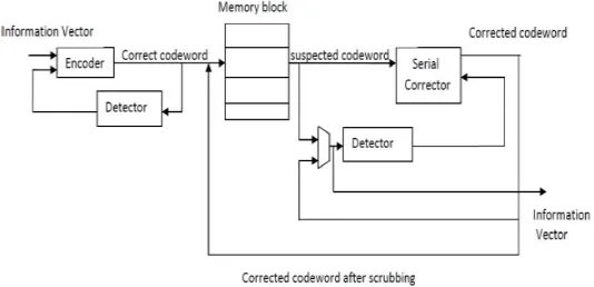
memory cells without damaging the circuit/device. The soft error is also referred to as a Single Event Upset (SEU). Different types of codes are used for this encoding and decoding process. For reducing errors due to channel noise error control codes are used and to correct the errors in data stored in the memory error correction codes are used. The memory system schematic with encoder and decoder is shown in Fig.1.
Fig.1 Memory System Schematic
The input data is encoded with redundant bits and it is stored in the memory. To mitigate the errors, decoder is used. It accomplishes this process by using the redundant bits.
II. LITERATURE REVIEW
[1]. Pedro Reviriego et al presented, Error Detection in Majority Logic Decoding of Euclidean Geometry Low Density Parity Check (EG-LDPC) Codes. The proposed method reduces the decoding time by stopping the decoding process when no errors are detected. The method accelerates the logic decoding of difference set low density parity check codes. The simulation results of proposed method shows that all tested combinations of errors affecting up to four bits are detected in the first three iterations of decoding.
[2]. P. Kalai Mani and V. Vishnu Prasath presented, Majority Logic Decoding of Euclidean Geometry Low Density Parity Check (EG-LDPC) Codes. The proposed method uses different set Low Density Parity Check (LDPC) codes to reduce hardware complexity and also the errors can be detected within a few iterations but the trick wires large decoding time.
[3]. M.Pramodh kumar and S.Murali mohan presented that serial One-Step Majority Logic Decoder for EG-LDPC Code detects errors in the first iteration and reduces the decoding time. These results extend the ones recently presented for DS-LDPC codes, making the modified one step majority logic decoding more attractive for memory applications.
[4]. Adline Priya proposed a decoder based on majority logic decoding for Low Power Error Correcting Codes. In this method, the decoder architecture for LDPC codes is designed.
[5]. Senbagapriya.S. presented an error detection technique based on Euclidean Geometry Low Density Parity Check (EG-LDPC) Codes for accessing memory frequently with minimum error. In the proposed method, the detection of errors uses serial one step Majority Logic Decoding which is complex because the number of cycles increases when the size of codeword increased.
[6]. M. Sakthivel, et al presented Performance comparison of EG-LDPC codes with maximum likelihood algorithm over non binary LDPC codes. The power consumed by the components used for the construction of NB-LDPC codes and EG-LDPC codes with ML algorithm was simulated using Xilinx Power Estimator series7 XPE 2013. The power is calculated by loading number of flip-flops and slice LUT registers used.
than five bit-flips in the three to nine cycles depending on the codeword length of the decoding process. This improves the performance of the design with respect to the traditional MLD approach.
[8]. R. Meenaakshi Sundhari, et al proposed an efficient majority logic fault detection to reduce the accessing time for memory applications using the quasi cyclic LDPC codes. Exhaustive simulation test output shows that the proposed system is able to detect any pattern of up to five bit-flips in the first three cycles of the decoding, which improves the performance of the design with respect to the traditional majority logic decoding approach.
III. EXISTING METHOD
The Majority logic decoding is effective scheme for decoding certain classes of block codes, especially for decoding certain classes of cyclic codes. The first majority logic decoding was devised by Reed for a class of multiple error correcting codes. Most majority logic decidable codes are cyclic codes. During memory access operation, the stored code words will be accessed from the memory unit. Code words are susceptible to transient faults. Therefore a corrector unit is designed to correct potential errors in the retrieved code word. Fig.2 shows the MLDD system with serial corrector.
A. Encoder
The information bits are fed into the encoder to encode the information vector. Let I = (i0, i1... i k−1) be k-bit information vector that will be encoded into n-bit codeword, C = (c0, c1... c n-1). For linear codes the encoding operation essentially
performs the following vector-matrix Multiplication.
C = I × G
Fig. 2. MLDD System with Serial Corrector
Where, G is a k × n generator matrix. A code is a systematic code if any codeword consists of the original k-bit information vector followed by (n – k) parity-bits. With this definition, the generator matrix of a systematic code must have the following structure.
G = [I: X]
Where, I is a k × k identity matrix and X is a k × (n−k) matrix that generates the parity-bits.
B. Memory Block
C. Corrector
During memory access operation, the stored code words will be accessed from the memory unit. Code words are susceptible to transient faults while they are stored in the memory. Therefore a corrector unit is designed to correct potential errors in the retrieved code words. In our design all the memory words pass through the corrector and any potential error in the memory words will be corrected.
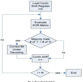
Fig. 3. Flow Chart for MLD
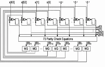
MLDD is straightforward, power decoder and capable of correcting several random bit-flips that depending in the number of the parity check equation. In the MLDD method, the 73-bit codeword input is encoded and decoded. If codeword does not contain any error, then the output will be processed in three iterations.
Serial corrector is used to correct all the n bits of the received codeword of a cyclic code. To correct each code-bit, the received encoded vector is cyclic shifted and fed into to the XOR gates. The serial majority corrector takes n cycles to correct an erroneous codeword. If the fault rate is low, the corrector block is used infrequently; since the common case is error free code words, the latency of the corrector will not have a severe impact on the average memory read latency. The serial corrector must be placed off the normal memory read path. The memory words retrieved from the memory unit are checked by detector unit. If the detector detects an error, the memory word is sent to the corrector unit to be corrected, which has the latency of the detector plus the n round latency of the corrector. The various units in the ML decoder are
Cyclic shift register: The cyclic shift register consists of two modules such as D flip-flop and Multiplexer.
XOR Matrix: The output from the shift register enters XOR Matrix in which the parity check equations are generated.
Majority Gate: If the output of majority gate is ‘1’ the current bit under decoding is faulty and it needs correction if ‘0’ correction is not necessary.
The input codeword bits are stored in the cyclic shift register and shifted to all the registers. It circulates all codeword bits of the register around both MSB and LSB ends with no loss of information.
IV. PROPOSED SYSTEM
The serial corrector is used more frequently and its latency can impact the system performance. Therefore parallel one step majority and pipeline correctors are implemented.
A. Parallel Corrector
The serial corrector is used more frequently and its latency can impact the system performance. Therefore a parallel one step majority corrector is implemented which is essentially n copies of the single one-step majority-logic corrector. The logic blocks are same for the parallel MLDD as in the serial MLDD. But required is more number of majority gates and correction gates, each gate is assigned for a single bit. Fig.4 shows a system integration using the parallel corrector.
Fig. 4. MLDD System with Parallel Corrector
In Parallel schematic each bit of the code word fed for error detection and correction consist of its parity check equation, correction gate and majority gate which is shown in Fig.5. It takes only single iteration to detect and correct the errors thereby greatly reducing the delay compared to serial corrector.
Fig. 5. Parallel Corrector using MLDD
B. Pipeline Corrector
The proposed decoder is designed using pipelining process and is shown in Fig.6. Due to the pipelining process the delay is comparatively lower than parallel corrector. All the memory words are pipelined through the parallel corrector. This way the corrected memory words are generated every cycle.
Fig.6. MLDD System with Pipeline Corrector
The detector in the parallel case monitors the operation of the corrector. If the output of the corrector is erroneous, the detector signals the corrector to repeat the operation.
V. RESULTS AND DISCUSSIONS
The serial, parallel and pipeline correctors are designed and simulated using Modelsim 6.3f and synthesized using Cadence Encounter. The results are shown in following figures.
Fig.7 Simulation result for Serial Corrector without error
Fig.8 Simulation result for Serial Corrector with error
The simulation output of the serial corrector with 5 bit flips is shown in Figure.8. Random inputs are fed to verify the functionality of the proposed design. For example it can be seen from the Figure 8, that for the input 011110111100011 the code word is 111111111111111.
Fig.9 Simulation result for Parallel Corrector
The simulation output of the parallel corrector with 5 bit flips is shown in Figure.9. Random inputs are fed to verify the functionality of the proposed design. For example it can be seen from the Figure 9, that for the input 111000111110011 the corrected code word is 111111111111111.
The simulation output of the pipeline corrector with 5 bit flips is shown in Figure.10. Random inputs are fed to verify the functionality of the proposed design. For example it can be seen from the Figure 10, that for the input 111000111110011 the corrected code word is 111111111111111.
The area, power and delay are compared between serial, parallel and pipeline correctors and the performance comparison between the correctors are shown in the below Table.1.
Table.1 Performance Comparison
Design Delay(ns) Area(µm2) Power(nW)
Serial 5.204 608.076 5916.778
Parallel 4.033 997.423 7025.002
Pipeline 3.892 1116.972 6984.030
The performance comparison shows that the pipeline corrector is efficient in terms of delay of 51.8% and hence achieves the power delay product (PDP) of 88.27%.
VI. CONCLUSION
In this paper, serial, parallel and pipeline correctors are designed. The pipeline corrector outperforms than serial and parallel correctors. The simulation result shows that all tested combinations of error affecting up to five bits are detected and corrected. For simulation process serial corrector used 15 cycles for write operation and 15 cycles for read operation. Also the parallel and pipeline corrector in which two cycles are used one for write operation and second one for read operation. Therefore the delay time is reduced with a percentage of 51.8.
REFERENCES
[1] Pedro Reviriego, Juan A. Maestro, and Mark F. Flanagan,”Error Detection in Majority Logic Decoding of Euclidean Geometry Low Density Parity Check (EG-LDPC) Codes”, IEEE Transactions on Very Large Scale Integration (VLSI) Systems, Vol. 21, No. 1, January 2013.
[2] Kalai Mani, P., and Vishnu Prasath, V., “Majority Logic Decoding Of Euclidean Geometry Low Density Parity Check (EG-LDPC) Codes,” International Journal of Innovative Research in Computer and Communication Engineering, Vol. 2, Special Issue 1, pp. 230-236, March 2014.
[3] Pramodh Kumar, M., Murali Mohan, S., “Serial one-step majority logic decoder for EG-LDPC code,” IJISET - International Journal of Innovative Science, Engineering & Technology, Vol. 1 Issue 6, August 2014.
[4] Adline Priya, “Low Power Error Correcting Codes Using Majority Logic Decoding,” International Journal of Engineering Research and Applications (IJERA) ISSN: 2248-9622, March 2014.
[5] Senbagapriya, S., “An Efficient Enhanced Majority Logic Fault Detection with Euclidean Geometry Low Density Parity Check (EG-LDPC) Codes for Memory Applications,” International Journal of Engineering Science and Innovative Technology (IJESIT), Vol. 2, Issue 6, pp. 85-93, November 2013.
[6] Sakthivel, M., Karthick Raja, M., Ragupathy, K.R., and Sathis Kumar, K., “Performance comparison of EG-LDPC codes with maximum likelihood algorithm over non binery LDPC codes,” International Journal of Computational Science and Information Technology (IJCSITY) Vol.2, No.2, May 2014.
[7] Manikandan, K., and Thiruselvi, G., “Fault Secure Memory Design using Difference Set Codes,” Special Issue of International Journal of Computer Applications (0975 – 8887) on International Conference on Electronics, Communication and Information Systems (ICECI 12). [8] Meenaakshi Sundhari, R., Sundarrasu, C., and Karthikkumar, M., “An Efficient Majority Logic Fault Detection to reduce the Accessing
time for Memory Applications,” International Journal of Scientific and Research Publications, Vol. 3, Issue 3, March 2013.