METHODS OF CALCULATION OF THE REACTOR BUILDING WITH
SEISMIC ISOLATION SYSTEM UNDER DYNAMIC LOADS
Peter Vasilyev1
1
Principal, CKTI-Vibroseism, Saint Petersburg, Russia (peter@cvs.spb.su)
ABSTRACT
Some issues concerning design of base-isolated Nuclear Power Plant (NPP) buildings for various dynamic loads has been analyzed. Problems regarded in the article include choice of calculation method, Seismic Isolation System (SIS) optimization issues, impact of the scale factor upon the behaviour of a seismic isolated object being under various dynamic loads.
INTRODUCTION
It is a primary tendency of the new nuclear era to build more and more of new nuclear power plants in a high seismicity zones. However, strong motion earthquake experience in the last period, e.g. Kashiwazaki-Karima and Fukushima NPPs cases have shown evidently that its seismic design basis was significantly underestimated. All of these trends lead to the constant increase of NPP’s seismic site demand and correspondingly SSC seismic capacity. This makes it necessary to design NPP units based on 0.4g PGA value or higher. The high level of seismic load creates a lot of technical problems, and leads to a substantial increase in the cost of the project. An alternative way to solve this problem is seismic isolation approach for safety related buildings, such as the reactor building. The interest in this approach is so high that some national nuclear regulators are developing specific guidelines for SIS. Among them are JNES (2012) and USNRC (2012). A similar document is being developed by the international community under the supervision of the IAEA (2012).
Authorities note that SIS is of utmost importance in respect of NPP safety. Despite the fact that failure of a single isolation unit can be permitted, failure of the whole system will lead to catastrophic consequences. At the same time SIS cannot be duplicated. Whole scale system testing is challenging. Therefore it is necessary to pay special attention to its justifying calculations.
CALCULATION METHODS
Presently there are two wide-spread structure calculation methods for seismic excitation. Those are the response spectrum method (RSM) and time-history analysis (THA). RSM cannot take into account non-linear effects. Neither can RSM obtain floor response spectra. Therefore in SIS design it can be used only at the earliest stages of design for preliminary estimates.
THA has two principle varieties: Direct THA and Modal THA. Let us analyze strengths and weaknesses (predominantly weaknesses) of these two methods.
Modal THA
This method has a merit of the possibility of setting damping, which will correspond to the code value in all the frequency range.
taking into consideration different damping levels in different parts of the construction. In such a case a separate damping ratio is calculated for every eigenmode.
Another of this method’s weaknesses is some inaccuracy connected to ignoring off-diagonal damping matrix elements. After transition to modal coordinates the set of motion equations look as follows:
(1) M, C and К in the equation 1 represent the modified matrices of mass, damping and stiffness respectively. Y is the modal coordinates vector. P is the modal load vector. As a result of transformations mass and stiffness matrices have a diagonalized form, while the damping one is in the general case a filled matrix. Traditionally only diagonal elements of the damping matrix are taken into consideration. This way the set of equations falls into separate conveniently integrated equations.
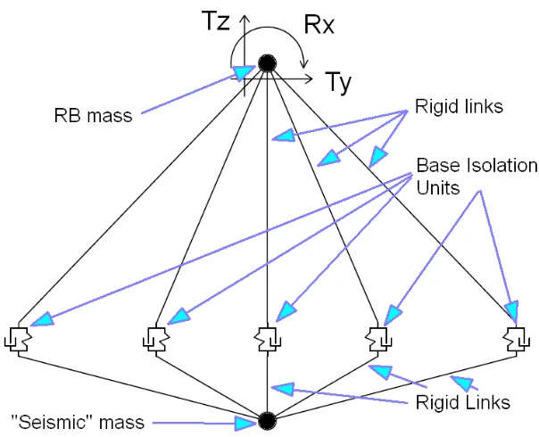
Let us examine the consequences of this approach, taking as an example a simple base-isolated system, consisting of two degrees of freedom. The first model of the Reactor Building (RB) is shown in Figure 1.
Figure 1. Simplified Reactor Building Model
Time-variant forces are exerted upon the so called “seismic” mass, which allows to reproduce the basis movement, while using the Direct THA method for calculations. When using Modal THA, the “seismic” mass is fixed.
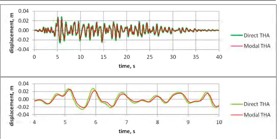
Calculations were made with the help of SOLVIA’03 code. At the first stage only one degree of freedom (Ty) was used during calculations. Results showed complete concurrence of the two methods. When using only one degree of freedom Tz, the results also concurred.
Figure 2. Comparison of vertical deformation of the vibration isolator using calculations following two methods
Direct THA
This method has a merit of taking into consideration non-linear effects, most importantly modeling non-linear isolator reactions and visco-elastic behaviour of damping devices. It has an opportunity to model elasto-plastic behavior and gaps, as well.
The weaknesses include problems that concern assigning damping in the construction material. Material damping is assigned in form of Rayleigh damping. In this case it is uniform for the whole construction and frequency dependent. Rayleigh damping consists of two parts. The first one, assigned by α coefficient, is proportional to the mass matrix. The second one, assigned by β coefficient, is proportional to the stiffness matrix. Test calculations have shown that using α coefficient for base-isolated structures is questionably and can lead to dangerous (nonconcervative) errors. In the following examples the Rayleigh damping assigned only by β coefficient is used (α = 0).
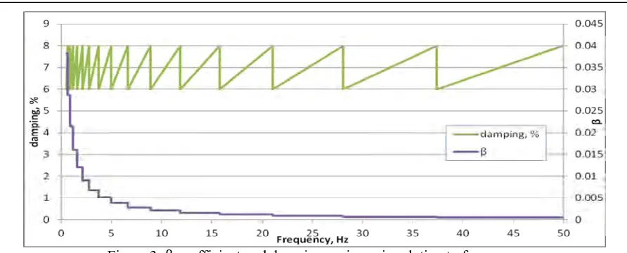
For an base isolated system (BIS) material damping has the greatest impact on the shape and magnitude of the floor response spectra (FRS). Let’s assume that we are designing a reinforced concrete building and would like to assign material damping by 7% of the damping critical value. Thereby we permit deviations of ±1% in the damping magnitude. We can then divide the frequency range we’re interested in into several subranges, in each of which this condition will be fulfilled at a particular β coefficient value. Figure 3 shows a graph of β coefficient and damping variance in relation to frequency.
Every i-th value of β coefficient shall correspond to its frequency subrange, where the damping magnitude can be changed within tolerable limits (see Table 1). Having designed the building using a βi,
we can hope for the calculated FRS to have an acceptable level of accuracy, at least, within the corresponding frequency subrange.
In order to examine β value impact upon the results of floor response spectra calculations, a detailed model of reactor building VVER-1200 (Figure 4) was used. Results for the point of reactor location on the X-axis are given below. Figure 5 demonstrates a collection of FRS received as a result of separate analysis runs at different βi values. The “precise” spectrum, received from the “correct” sections
Figure 3. β coefficient and damping variance in relation to frequency
Table 1. Rayleigh damping βi coefficients and corresponding frequency ranges
Range # 1 2 3 4 5 6 7 8
βi 3.82E-02 2.86E-02 2.15E-02 1.61E-02 1.21E-02 9.06E-03 6.80E-03 5.10E-03
Fleft, Hz 0.500 0.667 0.889 1.19 1.58 2.11 2.81 3.75 Fright, Hz 0.667 0.889 1.185 1.58 2.11 2.81 3.75 4.99
Range # 9 10 11 12 13 14 15 16
βi 3.82E-03 2.87E-03 2.15E-03 1.61E-03 1.21E-03 9.07E-04 6.81E-04 5.10E-04
Fleft, Hz 4.99 6.66 8.88 11.8 15.8 21.0 28.1 37.4
Fright, Hz 6.66 8.88 11.84 15.8 21.0 28.1 37.4 49.9
Figure 5. Floor Response Spectra. RB at Hard Soil. Damping 2%
Figure 6. Floor Response Spectra. RB at Base Isolation System. Damping 2%
Fast Nonlinear Analysis
Weak points of the above discussed methods can be overcome if the set of equations is written the following way:
(2)
There RNL(t) takes into account all non-linear reactions, local damping, etc. If we transfer RNL(t)
to the right part of equation and perform modal decomposition, we will be able to perform modal integration accounting for the non-linear behaviour of the elements. A more detailed method description can be found in the article by Mohraz (1992). This method was called Fast Nonlinear Analysis and implemented in SAP2000, dPIPE and several other codes.
BASE ISOLATION SYSTEM OPTIMIZATION
One sometimes hears the following opinions: “The optimal seismic isolation frequency is…” or “Damping of… is known to be optimal…” It is generally understandable that there is no universally optimal value. At the very least, such values will depend upon the following:
1) proportions of the protected object; 2) source acceleration time-histories; 3) type of goal function.
The results given below show parameter optimization of BIS for RB VVER-1200. Due to the large amount of calculations an optimization process requires, a simplified stick RB model was used, which included 18 degrees of freedom (DoF) plus 3 DoF for the “seismic” mass (see Figure 7). Isolation Units (100 items) were modeled with linear springs and viscous elements.
Artificial time-histories correspond to the response spectra of the site Akkuyu, Turkey, and are scaled to the horizontal components intensity of 0.4g. Comparison of the target spectrum to the artificial time-histories spectra can be found in Figure 8.
0 2 4 6 8 10 12
0.1 1 10 100
acc eler at io n, m /s 2 frequency, Hz UHRS Art-X Art-Y Art-Z
Figure 8. Response spectra of the artificial time-histories in comparison with the target spectrum (UHRS) Damping is at 7%
A combination of two parameters was adopted as the goal function: the peak acceleration at the reactor support level (A) and maximal displacement at isolation unit (D). The goal function was written as:
(3)
Aw and Dw in formula (3) are the weight coefficients. Aw and Dw should represent such values of acceleration and displacement, attainment of which would be equally unwanted. In this research the following weights were adopted: Aw = 0.4g, Dw = 100 mm.
Nominal frequencies, as well as nominal dampings for horizontal and vertical directions (4 parameters altogether) are used as optimization parameters. The nominal frequency is defined by the following formula:
(4)
The nominal damping is defined by the following formula:
(5)
where:
M is the mass of the building;
C is the total stiffness of isolation units;
B is the total viscous resistance of isolation units.
Evidently, real frequencies and damping ratios will diverge from these nominal values, but they are convenient to use as optimization parameters.
Figure 9. Goal Function Surface. Damping value is 40%. 3D View
Figure 10. Goal Function Surface. Damping value is 40%.Plane View
Table 2. Nominal frequencies and response values for some points (see Figure 10). Damping value is 40%
Point #
Nominal frequency,
Hz Displacement, mm Acceleration, g Goal
function
horizontal vertical X Y Z X Y Z
1 0.90 1.95 24 22 23 0.13 0.12 0.15 0.49
2 0.75 3.00 28 27 10 0.11 0.10 0.21 0.59
3 1.95 1.65 8 7 36 0.19 0.17 0.13 0.65
4 3.00 1.95 5 4 32 0.23 0.22 0.15 0.88
5 1.95 3.00 12 12 20 0.22 0.23 0.21 0.98
Values of relative displacements and response accelerations given in Table 2 seem highly optimistic even for the points, which are away from the optimal one. It should be, perhaps, mentioned that this result was achieved while using the damping value of 40% for both directions. This is possible, while designing a real BIS, attaining such a high damping level will be challenging. Let’s assume that we can achieve only the damping value of 20%. Then the goal function surface shall look the way it is shown in Figures 11 and 12. In Table 3 optimization parameters values for points, marked in Figure 12, are indicated along with the response parameters: accelerations, displacements and the goal function. Analyzing data from Table 3, one can decide that point 2 seems more attractive than the rest, due to the low vertical displacements. That may be a reason for further improvement of the formula for the goal function.
Figure 13 illustrates a comparison between response spectra at the reactor support level for some of the nominal damping values and nominal frequencies for the BIS. The comparison also includes a spectrum for a building without a BIS. The spectra are built for the horizontal direction (X) and 2% damping.
Figure 12. Goal Function Surface. Damping value is 20%.Plane View
Table 3. Nominal frequencies and response values for some points (see figure 12). Damping value is 20%
Point #
Nominal frequency,
Hz Displacement, mm Acceleration, g Goal
function
horizontal vertical X Y Z X Y Z
1 1.05 1.65 30 25 47 0.16 0.14 0.14 0.80
2 0.90 3.00 39 39 15 0.15 0.14 0.26 1.00
3 2.25 1.50 8 8 55 0.20 0.21 0.14 0.97
4 3.00 2.10 6 5 41 0.28 0.25 0.20 1.31
5 1.95 3.00 16 14 28 0.26 0.24 0.26 1.31
OTHER DYNAMIC LOADS
Plane Crash
Let’s analyze an often used case of loading during a plane crash of a large commercial aircraft (Boeing 747-400 with the mass exceeding 390 tons) onto the RB. Figure 14 shows the load-time curve.
Figure 14. Plane Crash Loading
It is necessary to note that the present research does not analyze destructions in the impact zone. They are supposed to be similar to those in a building without base isolation. Our main interest is the operation capacity of the BIS itself under such loading. Detailed RB model (see figure 4) was used for this analysis. Displacement values in Isolation Units for four variants are given in Table 4. Time-histories of those displacements is shown in Figure 15. In the calculations the plane crash occurred in the Y-direction.
Figure 16 illustrates a comparison between the response spectra for plane crash loading at the reactor support level for some of the nominal damping and nominal frequency values of the BIS. The spectra are built for the horizontal direction (Y) and 2% damping.
The results received indicate that a plane crash does not pose a threat for the SIS. It is mainly due to the large mass of the reactor building (230 000 tons) in respect to the mass of the aircraft. For lighter buildings displacements and accelerations will be higher and can present a real threat.
Table 4. Response parameters for the plane crash loading
Base Isolation variant
Max. Isolation Unit displacement, mm
Max. acceleration at reactor support, m/s2
dy dz ay az
Damping 40% point# 1 12.2 11.5 0.78 0.19
Damping 40% point# 5 3.9 6.7 0.79 0.18
Damping 20% point# 1 11.3 16.1 0.83 0.19
Figure 15. Base Isolation Displacements for the Plane Crash Loading. Isolation variant: damping 20%, point# 1
Figure 16. Floor response spectra for plane crash loading
Wind Loading
Test for wind loading was carried out in accordance with NUREG-0800 (2007) and ASCE/SEI 7-05 (2006). By way of example wind conditions for California were taken: design wind speed is 58 m/s (130 mi/h). Design wind pressure at the height of 40 m amounts to 2100 N/m2 (51.7 lb/ft2). Elementary estimate demonstrates that under such a load displacement of the isolation units is approximately 1 mm, which does not pose a threat. In this case taking dynamics into account cannot increase the estimate to a great extent, due to high level of damping in the system.
SCALE FACTOR
The question of the scale factor (SF) impact upon the behaviour of a seismic isolated object is of particular interest. Can one transfer the conclusions, drawn for some object onto a similar object of bigger or smaller size?
The invariance of the nominal frequency for the vertical direction means that the mass to stiffness ratio is permanent. Therefore the weight to stiffness ratio will also be permanent, and the weight displacements of the isolation units will not depend upon the scale.
The response parameters (displacement, acceleration) of a seismic isolated object under a seismic load are also invariant.
When calculating for a plane crash, the reduction of the object mass leads to an increase in its velocity after an inelastic collision. This conclusion is based upon the law of conservation of linear momentum. Consequently, displacements and accelerations of the object are inversely proportional to the linear size cubed, that is they will quickly grow with the decrease of the object size.
When calculating for wind loading it can be assumed that the wind pressure will not depend upon the scale to a great extent. Then the wind loading will be proportional to the linear size squared (area). Seismic isolation stiffness will be proportional to the linear size cubed. Therefore the construction displacement under wind loading will be inversely proportional to the linear size, that is it will grow upon the reduction of the object size.
CONCLUSION
1. Shortcomings of the popular calculation methods (Modal THA and Direct THA) are demonstrated. Weak points of these methods can be overcome in two ways: performing multiple calculations using Direct THA for different values of β or using a more advanced type of Modal THA, such as Fast Nonlinear Analysis.
2. It is shown that for the particular case of RB VVER-1200, and for a particular seismic impact optimal values of the nominal BIS frequencies can be found: fNVERT = 1.95 Hz,
fNHORIZ = 0.9 Hz. The growth of the damping always improves the value of the goal
function.
3. The plane crash load and strong winds do not pose a threat to BIS for such a large object as RB VVER-1200. These loads can be an issue for the smaller base isolated objects.
REFERENCES
JNES (2012). Technical Review Guidelines for Structures with Seismic Isolation (Draft).
USNRC (2012). Technical Considerations for Seismic Isolation of Nuclear Facilities (Draft for Comment).
IAEA (2012). Seismic Isolation Technical Report (Draft).
Mohraz, B., Jian, Y.C., and Chang, C.J. (1992). “A mode superposition procedure for seismic analysis of nonlinear base-isolated structures”, Earthquake Engineering, Tenth World Conference, Balkema, Rotterdam.
NUREG-0800 (2007). U.S. NRC Standard Review Plan.


