ISSN(Online): 2319-8753 ISSN (Print): 2347-6710
I
nternational
J
ournal of
I
nnovative
R
esearch in
S
cience,
E
ngineering and
T
echnology
(An ISO 3297: 2007 Certified Organization)
Website: www.ijirset.com
Vol. 6, Issue 6, June 2017
Power Generation from Exhaust Gas of an IC
Engine
Impha Y D1, Mahammad Yunus C2, Ajaygan K2, Mustaqeem Raza2, Mohammed Imran2, Harsha Raj K2
Assistant Professor, Department of Mechanical Engineering, Sahyadri College of engineering and management,
Mangalore, Karnataka, India.1
U.G. Student, Department of Mechanical Engineering, Sahyadri College of engineering and management, Mangalore,
Karnataka, India2
ABSTRACT: In this project, we modify a stationary diesel engine for producing power using turbine. Nowadays in automobile field many new innovating concepts are being developed. We are using the power from vehicle exhaust to generate the electricity which can be stored in battery for the later consumption. In this project, we are demonstrating a concept of generating power in a stationary multiple cylinder diesel engine by the usage of turbines. Here we are placing a turbine in the path of exhaust in the silencer. The turbine is connected to a dynamo, which is used to generate power. Depending upon the airflow the turbine will start rotating, and then the dynamo will also starts to rotate. A dynamo is a device which is used to convert the kinetic energy into electrical energy. The generated power is stored to the battery. It can be stored in the battery after rectification. The rectified voltage can be inverted and can be used in various forms of utilities.
KEYWORDS: Power generation, turbine, nozzle, dynamo.
I. INTRODUCTION
In recent the years the scientific and public awareness on environmental and energy issues has brought in major interests to the research of advanced technologies particularly in highly efficient internal combustion engines. Viewing from the socio-economic perspective, as the level of energy consumption is directly proportional to the economic development and total number of population in a country, the growing rate of population in the world today indicates that the energy demand is likely to increase. A heat engine is a system that performs the conversion of heat or thermal energy to mechanical work. Examples of everyday heat engines include the steam engine, the diesel engine, and the gasoline (petrol) engine in an automobile. Heat engines are designed to produce useful work only. The efficiency of a modern internal combustion engine is about 37% in a normal spark ignition engine. The energy in the form of heat is rejected by means of exhaust, circulating cooling water, lubrication oil & radiation.
Substantial thermal energy is available from the exhaust gas in modern automotive engines. Two-thirds of the energy from combustion in a vehicle is lost as waste heat, of which 40% is in the form of hot exhaust gas. There are many developments and technologies on waste heat recovery of exhaust gas from internal combustion engines (ICE).
If our idea is implemented effectively, the potential for energy conservation is massive. The report deals into the Working, Hardware requirements, and the advances made so far in implementing the idea. It also hints at future modifications intended.
II. DESIGNOFEQUIPMENT
2.1 COMPONENTS
➢ A diesel engine
➢ Nozzle
ISSN(Online): 2319-8753 ISSN (Print): 2347-6710
I
nternational
J
ournal of
I
nnovative
R
esearch in
S
cience,
E
ngineering and
T
echnology
(An ISO 3297: 2007 Certified Organization)
Website: www.ijirset.com
Vol. 6, Issue 6, June 2017
➢ Dynamo
➢ A rechargeable DC battery
➢ Mild steel for constructing frames
➢ Connecting wires
➢ Sheet metal
➢ Bearing to mount turbine
➢ Shaft
Turbine:
A steam turbine is a mechanical device that extracts thermal energy from pressurized steam, and converts it into rotary motion. It has almost completely replaced the reciprocating piston steam engine primarily because of its greater thermal efficiency and higher power-to-weight ratio. Because the turbine generates rotary motion, it is particularly suited to be used to drive an electrical generator – about 90% of all electricity generation in the United States is by use of steam turbines. The steam turbine is a form of heat engine that derives much of its improvement in thermodynamic efficiency through the use of multiple stages in the expansion of the steam, which results in a closer approach to the ideal reversible process.
Fig. 2.1Turbine
Diesel engine:
The diesel engine is an internal combustion engine in which ignition of the fuel that has been injected into the combustion chamber is caused by the high temperature which a gas achieves (i.e. the air) when greatly compressed .Diesel engines work by compressing only the air. This increases the air temperature inside the cylinder to such a high degree that it ignites atomised diesel fuel that is injected into the combustion chamber.
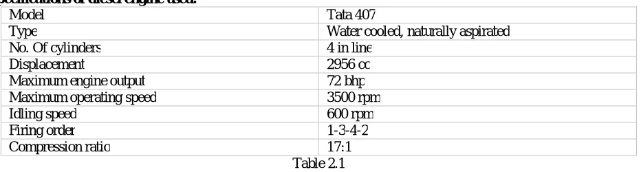
Specifications of diesel engine used:
Model Tata 407
Type Water cooled, naturally aspirated
No. Of cylinders 4 in line
Displacement 2956 cc
Maximum engine output 72 bhp
Maximum operating speed 3500 rpm
Idling speed 600 rpm
Firing order 1-3-4-2
ISSN(Online): 2319-8753 ISSN (Print): 2347-6710
I
nternational
J
ournal of
I
nnovative
R
esearch in
S
cience,
E
ngineering and
T
echnology
(An ISO 3297: 2007 Certified Organization)
Website: www.ijirset.com
Vol. 6, Issue 6, June 2017
Fig. 2.2 Diesel engine
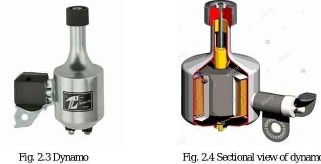
Dynamo:
Dynamo is an electrical generator. This dynamo produces direct current with the use of a commutator. Dynamo was the first generator capable of the power industries. The dynamo uses rotating coils of wire and magnetic fields to convert mechanical rotation into a pulsing direct electric current. A dynamo machine consists of a stationary structure, called the stator, which provides a constant magnetic field, and a set of rotating windings called the armature which turn within that field. On small machines the constant magnetic field may be provided by one or more permanent magnets, larger machines have the constant magnetic field provided by one or more electromagnets, which are usually called field coils.
Fig. 2.3 Dynamo Fig. 2.4 Sectional view of dynamo
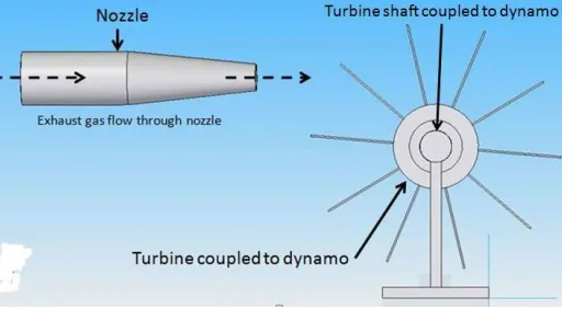
Nozzle:
ISSN(Online): 2319-8753 ISSN (Print): 2347-6710
I
nternational
J
ournal of
I
nnovative
R
esearch in
S
cience,
E
ngineering and
T
echnology
(An ISO 3297: 2007 Certified Organization)
Website: www.ijirset.com
Vol. 6, Issue 6, June 2017
Fig. 2.5 Nozzle
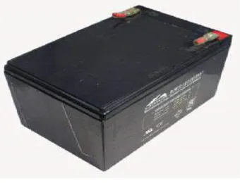
Battery:
It is a device user to store the power. The power is stored in the form of DC current only. There are many types of batteries are used Lead acid, lithium fluoride and in this work 8Amp current and 12 voltage specification is used.
Fig. 2.6 Rechargeable dc battery
Shaft:
A shaft is a rotating machine element, usually circular in cross section, which is used to transmit power from one part to another, or from a machine which produces power to a machine which absorbs power
.
ISSN(Online): 2319-8753 ISSN (Print): 2347-6710
I
nternational
J
ournal of
I
nnovative
R
esearch in
S
cience,
E
ngineering and
T
echnology
(An ISO 3297: 2007 Certified Organization)
Website: www.ijirset.com
Vol. 6, Issue 6, June 2017
Bearing:
A bearing is a machine element that constrains relative motion to only the desired motion, and reduces friction between moving parts. The design of the bearing may, for example, provide for free linear movement of the moving part or for free rotation around a fixed axis or, it may prevent a motion by controlling the vectors of normal forces that bear on the moving parts. Most bearings facilitate the desired motion by minimizing friction. Bearings are classified broadly according to the type of operation, the motions allowed, or to the directions of the loads (forces) applied to the parts.
Rotary bearings hold rotating components such as shafts or axles within mechanical systems, and transfer axial and radial loads from the source of the load to the structure supporting it. The simplest form of bearing, the plain bearing, consists of a shaft rotating in a hole. Lubrication is often used to reduce friction. In the ball bearing and roller bearing, to prevent sliding friction, rolling elements such as rollers or balls with a circular cross-section are located between the races or journals of the bearing assembly.
Fig. 2.8 Bearing
III.EXPERIMENTALSETUP
ISSN(Online): 2319-8753 ISSN (Print): 2347-6710
I
nternational
J
ournal of
I
nnovative
R
esearch in
S
cience,
E
ngineering and
T
echnology
(An ISO 3297: 2007 Certified Organization)
Website: www.ijirset.com
Vol. 6, Issue 6, June 2017
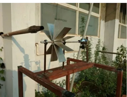
Fig. 3.1 Turbine setup with nozzle
IV.CALCULATIONS
4.1 Exhaust gas flow rate
To determine theoretical nozzle outlet velocity:
Continuity equation, Q=A1V1=A2V2 Velocity at nozzle outlet,
V2=A1V1/A2 V2=D12V1/D22
Where A1 is the cross sectional area at section 1 A2 is the cross sectional area at section 2 V1 is the velocity of exhaust gases from silencer Trial No Speed of engine
(rpm)
Velocity of exhaust gas at silencer end
(m/s)
Expected velocity of exhaust at nozzle end
(m/s)
1 950 12.9 51.6
2 1120 16.1 64.4
3 1230 18.1 72.4
Table 4.1 Exhaust gas Velocity test
Flow rate, Q=A*V
ISSN(Online): 2319-8753 ISSN (Print): 2347-6710
I
nternational
J
ournal of
I
nnovative
R
esearch in
S
cience,
E
ngineering and
T
echnology
(An ISO 3297: 2007 Certified Organization)
Website: www.ijirset.com
Vol. 6, Issue 6, June 2017
Therefore,
Q= 4.9087*10-4*51.6 (at an engine speed of 950 rpm) Q=0.0253 m3/s
At an engine speed of 1120 rpm, Q=0.0316 m3/s
At an engine speed of 1230 rpm, Q=0.0355 m3/s
Area Swept,
A= (22/7) x radius of turbine2 Velocity of the Turbine,
V= ((22/7)* D x N)/60 Where D=diameter of turbine
N=number of revolution per minute Power available at the turbine,
P= (1/2) * Density * (Velocity)3*Cp*Area swept
4.2 Model Calculation
Swept area by the turbine, A = (22/7) x radius2 A=3.14 x (0.115) 2 A=0.04152 m2
Velocity of the turbine, V= ((22/7) x D x N)/60 V=3.14*0.115*60/60
V=0.3611 m/s
Power of the flowing exhaust gas =1/2*ρ* area x (velocity)3 * Cp
=1/2 x1.23 x 0.04152x (0.3611)3*0.4 =4.8*10-4 Watts
4.3 Impulse force acting on the turbine
Mass flow rate, m=ρ*Q Where ρ is the density in kg/m3
Q is the volume flow rate in m3/s Impulse force,
F=m*V
Where V is the velocity of flow of exhaust gases in m/s
At engine speed of 950rpm,
Mass flow rate,
m=1.23*0.02503 m=0.03079kg/s Impulse force,
F=0.03079*51.6 F =1.588 N
At an engine speed of 1120rpm,
Mass flow rate,
m=1.23*0.0316 m=0.03886 kg/s Impulse force,
ISSN(Online): 2319-8753 ISSN (Print): 2347-6710
I
nternational
J
ournal of
I
nnovative
R
esearch in
S
cience,
E
ngineering and
T
echnology
(An ISO 3297: 2007 Certified Organization)
Website: www.ijirset.com
Vol. 6, Issue 6, June 2017
F =2.503 N
At an engine speed of 1230rpm,
Mass flow rate,
m=1.23*0.0353 m=0.04347 kg/s Impulse force,
F=0.04347*72 F =3.129 N
4.4 Power generated by turbine
Torque, T=F*R
Where F is impulse force in Newton
R is distance from centre of shaft to the point where exhaust gas hit the blades in metre Power generated,
P=2πNT/60 watts
Where N is speed of turbine in RPM T is torque in Nm
At engine speed of 950rpm,
Torque,
T=1.588*0.09 T=0.1492 Nm Power generated,
P=2π*70*0.1492/60 P =1.0936 Watts
At engine speed of 1120rpm,
Torque,
T=2.503*0.09 T=0.225 Nm Power generated,
P=2π*125*0.225/60 P=2.945 Watts
At engine speed of 1230rpm,
Torque,
T=3.129*0.09 T=0.2816Nm Power generated,
ISSN(Online): 2319-8753 ISSN (Print): 2347-6710
I
nternational
J
ournal of
I
nnovative
R
esearch in
S
cience,
E
ngineering and
T
echnology
(An ISO 3297: 2007 Certified Organization)
Website: www.ijirset.com
Vol. 6, Issue 6, June 2017
4.5Graphs
Fig. 4.1 Turbine speed (rpm) v/s engine speed (rpm)
Fig. 4.2 Power generated (Watts) v/s Turbine speed (rpm)
Fig. 4.3 Power generated (Watts) v/s Engine speed (rpm) 0
50 100 150 200
0 200 400 600 800 1000 1200 1400
Turbine speed v/s Engine speed
0 1 2 3 4 5 6
0 50 100 150 200
Power Generated v/s Turbine speed
0 1 2 3 4 5 6
0 200 400 600 800 1000 1200 1400
ISSN(Online): 2319-8753 ISSN (Print): 2347-6710
I
nternational
J
ournal of
I
nnovative
R
esearch in
S
cience,
E
ngineering and
T
echnology
(An ISO 3297: 2007 Certified Organization)
Website: www.ijirset.com
Vol. 6, Issue 6, June 2017
V. CONCLUSION
From this project, it has been identified that there are large potentials of energy savings through the use of waste heat recovery technologies. Waste heat recovery entails capturing and reusing the waste heat from internal combustion engine and using it for heating or generating mechanical or electrical work. It would also help to recognize the improvement in performance and emissions of the engine if these technologies were adopted by the automotive manufacturers.
The study also identified the potentials of the technologies when incorporated with other devices to maximize potential energy efficiency of the vehicles. The project carried out by us made an attempt to generate electricity in engine exhaust unit. This project has also reduced the cost involved in the concern.
REFERENCES
1) International Journal of Innovative Research in Science, engineering and technology.Vol.4, Special issue 6, May 2015. Generation of electricity by using exhaust gases from bike.