Transactions of the 17th International Conference on Structural Mechanics in Reactor Technology (SMiRT 17) Prague, Czech Republic, August 17 –22, 2003
Paper # B03-5
Numerical Analysis of Flow-induced Vibration using Overset Grid System
Shigeaki Kuroda1),Kazuya Ogasawara1)
1) University of Electro-Communications
ABSTRACT
Flow around one or more elastically supported circular cylinders in a uniform flow is investigated numerically. A system of overset grids is used for geometrically complicated flow domain. Two grid systems are generated in a flow field. The main grid is a Cartesian grid that covers the entire computational region, and the sub grid is a cylindrical grid that covers an area around a cylinder. The main grid is stationary, whereas the sub grid is fixed to the oscillating cylinder and moves with the flow-induced vibration of the cylinder. The finite difference technique and the Runge-Kutta method are used to solve the Navier-Stokes equation and the momentum equation for the cylinder. Some illustrated examples are solved and numerical results of flow field and oscillation of cylinders are presented.
Key words: Computational fluid dynamics, overset grid, Cartesian grid, cylindrical grid, boundary fitted coordinate, flow induced vibration, flow structure interface, finite deference technique, MAC method, Runge Kuta, drug coefficient, lift coefficient first excitation, second excitation, reduced velocity. complicated geometry
INTRODUCTION
Flow-induced vibration is an important problem in many engineering fields, and has been the subject of many numerical and experimental studies. An overlapping grid system has recently come into wide use in numerical analysis of flow in a geometrically complicated computational domain[1-5]. In this study, the overlapping grid system is applied to solve the flow field around objects of arbitrary shape moving in an unsteady flow. Elastically supported cylinders in unsteady flow oscillate in the x and y directions by fluid force acting on the surfaces of the cylinders.
Some sample problems are solved and the numerical results obtained by use of the proposed overlapping grid system are compared with the results obtained by a single boundary fitted coordinate system. The systems are compared in terms of the time histories of drag coefficient, lift coefficient, and locus of the oscillating cylinder. Two results show
farily close agreement. Flow-induced vibration of a single cylinder, a 4-cylinder bank, and a 9-cylinder bank are
numerically investigated. As reduced velocity increases, loci of the oscillating cylinders change, and some typical patterns are illustrated. The proposed method can be extended to the analysis of flow around a moving body having a complicated configuration.
Numerical Procedure
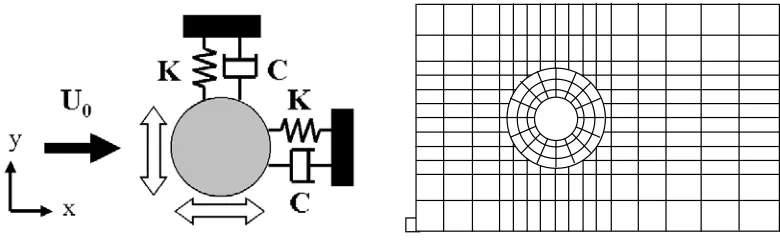
Figure 1 shows a schematic model of an elastically supported circular cylinder. The cylinder is supported by elastic springs and dampers.
Fig. 1 Schematic model of cylinder. Fig. 2 Overlapping grid system.
Basic Equation of Flow
( )
u u - u u 2 ∇ + ∇ = ∇ ⋅ + ∂ ∂ Re 1 P t (1) 0 =≡divu
D (2)
= + + = + + L D C Ky y C y M C Kx x C x M & && &
&& (3)
Eqs (1) and (2) are solved by the MAC method, and Eq (3) by the Runge-Kutta method. Numerical processing proceeds in the main grid and sub grid alternately. Interpolation is performed at the boundary of the main and sub grid, and values of velocity and pressure near the boundary of the two grids are transferred from the main grid to the sub grid and from the sub grid to the main grid alternately until a converged solution is obtained.
NUMERICAL RESULTS
Single cylinder
In order to demonstrate the performance of the overlapping grid system for the moving boundary problem, flow-induced vibration of a single cylinder in a uniform flow is studied. The acuracy and reliability of present numerical method are evaluated by comparing the results obtained by the present method and results calculated by use of a single O-type boundary fitted coordinate system. The calculation is performed at Re=1,000 and Vr=2.2.
Figure 3 compares loci of the cylinder as calculated by the respective grid systems.
Reduced velocity Vr
RM
S
(x
,y
) xy
0 1 2 3 4
0 0.05 0.1 0.15
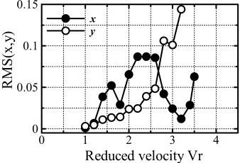
Fig 3 Comparison of two grid systems. Fig. 4 Reduced velocity versus amplitude of vibration.
The shapes of figure-8-type loci agree fairly well.
Figure 4 shows the relation between the amplitude of oscillation and reduced velocity. In-line oscillation begins at Vr=1.2. The first peak of amplitude appears at a reduced velocity 1.6 and the second peak at 2.2. As has been reported
by King et.al[6], the first peak (first excitation) is caused by a twin vortex from both sides of the cylinder.
Figures 5 and 6 show the locus of oscillation and flow patterns at Vr=1.4 and Vr=2.2. The vortex shedding corresponds to line oscillation of the cylinder. At Vr=1.4 (first excitation), the twin vortex suppresses the cross line oscillation; in-line oscillation is greater than the cross-in-line oscillation. At Vr=2.2 (second excitation) a cylinder resonates to the alternate vortex shedding behind the cylinder, and the in-line oscillation is greater than the cross-line oscillation Typical twin vortex and alternative Karmann vortex can be observed in both figures.
N di i l lit d
N on -di m en si ona l a m pl it ud e y
-0.05 -0.025 0 0.025 0.05 -0.05
-0.025 0 0.025 0.05
NNon di i l lit d
-dim ens io na l a m plitude y
-0.15 -0.075 0 0.075 0.15 -0.15
-0.075 0 0.075 0.15
2×2 Cylinder bank
Flows past an elastically supported 2x2 square bank of cylinder are investigated, and characteristics of fluid-induced
vibration are studied. The calculating conditions are as follows; diameter=0.01m, density=2.69x10³kg/m3,
mass=6.33x10⁻²kg, damping coefficient=0.204N
•s/m.
Figure 7 shows a schmatic of the four-cylinder bank. The dimensionless width between adjacent cylinders is 3.0, and
four cylinders are set on the vertices of a square. The symbols for the respective cylinders are shown in the figure.
U0
S
S
1,1 1,2
2,1 2,2
Fig. 7 2×2 square matrix of cylinders.
Figure 8 shows the amplitude of vibration of each cylinder in the x and y directions. The two upstream cylinders (1,1), (1,2) approach each other while moving toward the upstream direction, whereas the two downstream cylinders (2,1), (2,2) separate from each other while moving toward the downstream direction. With the passage of time, the reverse modes of vibration are observed; the two upstream cylinders (1,1), (1,2) separate from each other while moving towards the downstream direction, whereas the two downstream cylinders (2,1), (2,2) approach each other while moving towards the upstream direction. The cross-flow vibrations of the two pairs of cylinders are the reverse modes. The oscillating flow past the upstream cylinders affects the two downstream cylinders, causing large cross-line vibration. Figure 9 shows the streamlines and pressure distribution near the cylinder bank. Animation shows that the upstream pair of cylinders and the downstream pair of cylinders vibrate in reverse modes; when the upstream pair approach each other, the downstream pair separate from each other. As compared with vibration of the upstream pair of cylinders, vibration of the downstream pair of cylinders is strong and random. The luci of cylinders are not always periodic and further understanding of this flow induced vibration requires in-depth calculation.
Non-dimensional time T
x-am
pl
itu
de
(1,2)
(1,1)
(2,2)
(2,1) -0.3 -0.15 0 0.150.3
-0.3 -0.15 0 0.150.3
-0.3 -0.15 0 0.150.3
20 30 40 50
-0.3 -0.15 0 0.15 0.3
Non-dimensional time T
y-a
m
pl
itu
de
(1,2)
(1,1)
(2,2)
(2,1) -0.3 -0.15 0 0.15 0.3
-0.3 -0.150 0.15 0.3
-0.3 -0.15 0 0.15 0.3
20 30 40 50
-0.3 -0.15 0 0.15 0.3
(a) In-line (x-direction) Oscillation (b) cross-line (y-direction) oscillation
Fig. 8 Amplitude of vibration of each cylinder.
(a) T=45.6 (b) T=46.8
3×3 Cylinder bank
Flows past 3x3 cylinder bank are investigated. The calculating conditions are: diameter=0.06 m, density 7.86x10³
kg/m3, mass=4.0 kg, damping coefficient=0, Re=100, Vr-2.2.
Figure 10 shows the schematic model of the 3x3 cylinder bank. The dimensionless distance between each cylinder is 3.
U0
S
S
1,1 1,2
2,1 2,2 2,3
1,3 3,3
3,2
3,1
Fig. 10 Schmatec model of 3×3 square matrix.
Fixed cylinders
Fig 11 shows the time history of CD and CL of cylinder (2,2). The time variation of CD is small. The change of CL of
the three upstream cylinders (1,1), (1,2), (1,3) is relatively small, the amplitude of the middle three cylinders (2,1) , (2,2), (2,3) is medium, and the amplitude of the three downstream cylinders is largest.
Figure 12 shows the flow pattern past the fixed cylinder bank, including streamlines and pressure distribution.
Non-dimensional time T CD
,CL
CD , CL
10 20 30
-2 -1 0 1 2 3
(a) T=24.8 (b) T=27.6
Fig. 11 Time variation of Cd of Cylinder (2,2). Fig. 12 Flow past the 3x3 cylinder matrix (Stationary state).
Oscillating cylinders
Figure 13 shows the time variation of CD and CL of the oscillating cylinder (2,2). The change of CL is similar to
that under stationary conditions, whereas the change of CD differs from that under stationary conditions.
Figure 14 shows the flow pattern around an oscillating cylinder bank. The flow patterns of the stationary state and the vibrating state are almost same. The effects of vibration on the flow pattern are not significant as the amplitude of vibration is less than 10% cylinder diameter.
Non-dimensional time T CD
,CL
CD , CL
10 20 30
-2 0 2 4
(a)T=24.8 (b)T=27.6
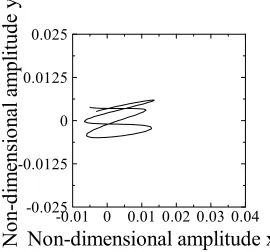
Figure 15 shows the locus of cylinder (2,2). The loci of cylinders are classified into three types. The locus of the three upstream cylinders is elliptical, stretching in the direction of flow. Then middle three cylinders have a figure-8-type locus. The locus of the three downstream cylinders is deformed circular type, streching in the cross-line direction.
Non-dimensional amplitude x
No
n-di
m
ensi
ona
l am
pl
itud
e
y
-0.01 0 0.01 0.02 0.03 0.04 -0.025
-0.0125 0 0.0125 0.025
Fig. 15 Time variation of Cd, Cl cylinder(2,2)
Conclusion
The overset grid systen is installed in order to analyze flow-induced vibration. The accuracy of the proposed
method is confirmed and analysis of flow past 2x2 and 3x3 cylinder banks are performed, and flow patterns, CD , CL,
and the loci of oscillations are obtained.
Nomenclature
d dimensionless diameter
U0 Velocity
Re Reynolds number
U Velocity vector
P Pressure
x y dimensionless co-ordinate
CD CL drag coefficient and lift coefficient
Vr Reduced velocity
M dimensionless mass of cylinder
K dimensionless spring coefficient
C dimensionless dumping coefficient
ρ dnsity of fluid
ν kinematics viscosity
REFERENCES
(1) Pan H. and Damodaran M., “Parallel computation of viscous incompressible flows using Godunov-projection
method on overlapping grids”, International Journal for Numerical Methods in Fluids, Vol. 39, 2002, pp. 441-463
(2) Burton T. M. and Eaton J. K. “Analysis of fractional step method on overset grids”, Journal of Computational
Physics Vol. 177, 2002, pp. 336-364
(3) Prewitt N. C., Belk D. M. and Shyy W., “Parallel computing of overset grids for aerodynamic problems with
moving objects”, Progress in Aerospace Science, Vol. 36-2, 2000, pp. 117-172
(4) Freitas C. J. and Runnels S. R., “Simulation of fluid-structure interaction using patched-overset grids”, Journal of
Fluids and Structures, Vol. 13-2, 1999, pp.191-207
(5) Meakin R. L., “Adaptive spatial partitioning and refinement for overset structured grids”, Computer Methods in
Applied Mechanics and Engineering, Vol. 189-4, 29, 2000, pp. 1077-1117