Timer Based Electric Heating Pad
Arushi Vats1, Sakshi Sethi2
B.Tech Student, Department of Biomedical Engineering, Amity University, Manesar, Gurgaon, Haryana, India1
Assistant Professor, Department of Biomedical Engineering, Amity University, Manesar, Gurgaon, Haryana, India2
ABSTRACT: This project deals with the designing of biomedical related equipment used for pain relieving by time
dependent heat therapy. A timer can be constructed using various components to integrate numerous functions like
setting the count, start, stop, reset and display. A microcontroller-based industrial timer is programmed and used as a time totalizer. In this project we are making simple design based on 40-pin Atmel AT89S52 microcontroller that performs count-down operation from 0000 up to 9999 minutes or second with four 7-segment display showing the actual time left. The electric heating pad is then connected to the timer circuit through cables. Heat therapy is widely accepted and commonly used for pain relief. Also, a step down transformer is used to power the timer circuit.
KEYWORDS: Microcontroller, AT89S52, Seven-segment display, heating pad, energizes.
I. INTRODUCTION
In today’s world, patients should be encouraged to actively participate in self care whenever possible. Non-invasive physical equipments can be used concurrently with biomedical interventions to manage pain during all phases of treatment. Thus, we are motivated to develop a low cost device which is user friendly, portable and easy to use in relieving different types of pain such as menstrual cramps, help women in labor pain after delivery, after surgery pain management etc.
The device is made more acceptable by adding a timer control which allows to, set the timer automatically to shut off so that patients can access treatment in a timely manner. The effectiveness of these equipments depends on the patient’s participation. The foremost important objective of developing such a device is it should be low cost, user friendly and portable, easy to use equipment that is not bulky and safe. It should be containing a light weight electric heating pad, digital timer controller with auto shut off, extra long power cord, the pad is flexible and can wrap around any body part and lastly, this pad does not emit dangerous radiations.
II. BASIC TERMINOLOGY
Fig 1: Pin Configuration of AT89S52 [1]
III. CIRCUITRY
Port P0 of microcontroller AT89S52 is configured for segments of the 7-segment display. Port 0 is an 8-bit open-drain bi-directional I/O port. Port 0 is pulled up with 10-kilo-ohm resistor network. Port pins P0.0 through P0.6 are connected to pins of segments ‘a’ through ‘g’ via resistors R2 through R8, respectively. Port P0.7 is connected to decimal via resistor R9. Resistors R2 through R9 are used as current limiter for various segments of displays, respectively. Port 2 is used to control DIS1 through DIS4. Port 2 is an 8-bit bi-directional I/O port with internal pull-ups. When port-2 pin is low, the transistor conducts and provides supply to the common pin of 7-segment display. Port pins P2.5 through P2.2 control DIS1 through DIS4 with the help of transistors T1 through T4, respectively.
Fig 2: Circuit Diagram of Timer [2]
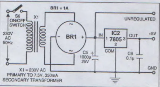
IV. POWER SUPPLY
The AC mains, is stepped down by transformer X1 to deliver a secondary output of 7.5V at 350 ma. The transformer output is rectified by a full-wave bridge rectifier BR1, filtered by capacitor C5 and regulated by IC2. Capacitor C6 by passes any ripple present in the regulated output. Unregulated power supply is used for relay RL1. (figure.3)
Fig 2: Circuit Diagram of Power Supply
V. PROPOSED LAYOUT
Idea about the Project
automatically by timer for the time duration he wants to. Moreover the user will be given an option to adjust the time implemented by the software in the microcontroller provided along with the timer device.
VI. OPERATION
Switch ON the circuit using the ON/OFF switch S6. Power-on-reset will first reset the microcontroller chip. The ‘select’ key will select the 2 modes between seconds’ and ‘minutes.’ ‘0’ is displayed for the seconds and ‘1’ is displayed for the minutes on the hundred’s digit of the 7-segment display (DIS3) respectively. ‘Up’ and ‘Down’ keys increment and decrement the time setting in seconds and minutes respectively. After setting the desired time select or push the ‘set’ switch which then energizes the relay. The timer counts down for the set time and once the display becomes zero the relay de-energizes. The timer will stop before preset time by pressing ‘start’ key again.
VII. DESCRIPTION OF MICROCONTROLLER
The AT89S52 is a low-power, high-performance 8-bit CMOS microcontroller with 8Kbytes of in-system programmable Flash memory. The device is manufactured using Atmel’s high-density non-volatile memory technology and is compatible with the industry-standard 80C51 instruction set and pin out [4]. The on-chip Flash allows the program memory to be reprogrammed in-system or by nonvolatile memory programmer. By combining a versatile 8-bit CPU with in-system programmable Flash on a monolithic chip, the AT89S52 is a powerful microcontroller which provides a highly-flexible and cost-effective solution to many embedded control applications. The AT89S52 provides the following standard features: 8K bytes of Flash, 256 bytes of RAM, 32 I/O lines, Watchdog timer, two data pointers, three 16-bit timer/counters, a six-vector two-level interrupt architecture, a full duplex serial port, on-chip oscillator, and clock circuitry. In addition, the AT89S52 is designed with static logic for operation down to zero frequency and supports two software selectable power saving modes. The Idle Mode stops the CPU while allowing the RAM, timer/counters, serial port, and interrupt system to continue functioning. The Power-down mode saves the RAM contents but freezes the oscillator, disabling all other chip functions until the next interrupt or hardware reset.
Memory
MCS-51 devices have a separate address space for Program and Data Memory. Up to 64K bytes each of external Program and Data Memory can be addressed. Program Memory-If the EA pin is connected to GND, all program fetches are directed to external memory. On the AT89S52, if EA is connected to VCC, program fetches to addresses 0000H through 1FFFH are directed to internal memory and fetches to addresses 2000H through FFFFH are to the external memory. Data Memory-The AT89S52 implements 256 bytes of on-chip RAM. The upper 128 bytes occupy a parallel address space to the Special Function Registers. This means that the upper 128 bytes have the same addresses as the SFR space but are physically separate from SFR space. When an instruction accesses an internal location above address 7FH, the address mode used in the instruction specifies whether the CPU accesses the upper 128 bytes of RAM or the SFR space. Instructions which use direct addressing access the SFR space.
Interrupts
Oscillator
XTAL1 and XTAL2 are the input and output, respectively, of an inverting amplifier that can be configured for use as an on-chip oscillator. Either a quartz crystal or ceramic resonator may be used. To drive the device from an external clock source, XTAL2 should be left unconnected while XTAL1 is driven. There are no requirements on the duty cycle of the external clock signal, since the input to the internal clocking circuitry is through a divide-by-two flip-flop [5].
VIII. SOFTWARE PROGRAM
The source program is written in ‘C’ language and compiled with Keil Microvision 3 IDE. It is well commented and easy to understand. Download C51 V808A.EXE from the web address as ‘www.keil.com/demo/eval/c51.htm.’ This file is a freely available and self-extracting setup program for Keil Microvision 3 IDE.
Normally, when there is no interrupt, the microcontroller executes ‘while’ loop in the main function. Here it scans the keys and acts according to the key pressed.
Two interrupts are enabled in the software namely, timer 0 and timer 2. Timer 0 counts milliseconds, which are then accumulated to seconds or minutes according to the user selection. Timer 2 drivers the displays in multiplex mode. For time counting, timer 0 is initialized by the void Timer0- init (unsigned char Timer0h, unsigned char Timer01) function.
Timer 0 interrupts the microcontroller every millisecond. When interrupted by timer 0, the microcontroller executes the void isr- t0(void) function wherein it increments two counter variables, namely, Timer0counter and Led Counter. Timer
0Counter is responsible for counting the number of milliseconds elapsed and increments the minutes/seconds counter according to the mode selected (‘seconds’ or ’minutes’ count). Once the set value is reached, the timer-0 interrupt is disabled and time counting stops. The LED counter makes the dot LED of the unit’s digit flash every second once. Display-driving of by the built-in timer 2. Timer 2 is initialized by the void Timer2- init(unsigned char Timer21)
functions. Timer 2 gives an interrupt to the microcontroller to switch on the common pin of each 7-segment display for every two milliseconds. When an interrupt occurs, the void ISR-12(void) function is executed and the microcontroller
returns to ‘while’ loop in the main function.
IX. ELECTRIC HEATING PAD
Heating pads are covered and applied directly to the skin's surface. These pads are normally either gel-filled or wheat-filled or water wheat-filled. Here, we are using a silica gel wheat-filled pad. Some pads can be molded to fit the affected part of the body moreover; larger pads can be used to relieve back or neck pain. The electric pad consists of a waterproof rubber or plastic pad connected by two wires to an electrical control unit that has a heating element and motor. Gel circulates through hollowed channels in the pad to the control unit where it is heated (or cooled). One can adjust the temperature setting by shifting a plastic key in the control unit that has a temperature regulating unit for high, medium, or low settings. A hazard of dry heating pads is falling asleep with them on; burns can then occur on the surface of the skin. The heating pad is equipped with an automatic shutoff feature i.e. after a period of minutes or hours, it turn off automatically using the timer facility. Also heating pads work on the principle of conduction.Conductionis the direct transfer of energy between two objects in physical contact with each other. A difference in temperature is necessary to initiate the movement of kinetic energy from one molecule to another and the energy moves from an area of high temperature to an area of lower temperature.
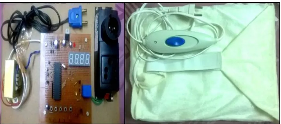
X. SIMULATION AND RESULTS
Fig 4: Hardware Model of Timer Based Electric Heating Pad
XI. CONCLUSION
In this project, instead of portable 9V batteries, transformer is used for continuous power supply, this is beneficial as portable batteries drain out faster because of the large amount of current used in the circuit but on the other hand it limits the device’s portability as a power source is always required near the patient to make the device work. The device will help give temporary relief from minor muscle and joint pain and stiffness, joint pain associated with arthritis, relief from muscle spasm, minor sprains and strains and minor muscular back pain, it will temporarily increase the local circulation where applied and help in muscles to relax. Moreover, it is a very cost effective device providing timer controller at a low cost in the equipment. Figure 4 shows the demonstrated model of this project.
REFERENCES
1. International Journal of Computer Applications (0975 – 8887) Volume 38– No.1, January 2012
2. IJISET - International Journal of Innovative Science, Engineering & Technology, Vol. 2 Issue 4, April 2015.
3. Dr.Clarkinfraredheatingpadmanual.pdf
4. International Journal of Advanced Research in Electrical, Electronics and Instrumentation EngineeringVol. 2, Issue 2, February 2013
5. International Journal of Computer Applications (0975 – 8887) Volume 38– No.1, January 2012 19 Microcontroller based Intelligent Digital
Volume Controller with Timer Diptarup Paul Department of Computer Science and Engineering JIS College of Engineering Kalyani, Nadia-741235, West Bengal, India Sukalyan Som Department of Computer Science Barrackpore Rastraguru Surendranath College 85, Middle Road & 6, Riverside Road, Kolkata– 120
6. Hometreatmentforpainrelief.pdf
7. IOSR Journal of Electrical and Electronics Engineering (IOSR-JEEE) e-ISSN: 2278-1676,p-ISSN: 2320-3331, Volume 9, Issue 1 Ver.II
(Jan.2014),PP01-www.iosrjournals.org
8. AT89S52Datasheet,http://www.atmel.com/dyn/resources/prod_documents/doc1919.pdf
9. http://www.atmel.com/devices/at89s52.aspx?tab=documents
10. kitsnspares.com/admin/pdffiles/industrial%20timer.pdf
11. www.electronicsforu.com/EFYLinux/cIrcuit/.../CI‐01‐prog‐timer.pdF
12. http://www.academia.edu/2545101/Programmable_Timer_Using_Microcontroller
13. https://electricalnotes.wordpress.com/2012/03/13/direct‐on‐line‐starter/
14. www.circuitstoday.com/555‐timer
![Fig 1: Pin Configuration of AT89S52 [1]](https://thumb-us.123doks.com/thumbv2/123dok_us/1642121.1205240/2.595.219.376.202.443/fig-pin-configuration-of-at-s.webp)