Multi-hop Adaptive Link State Optimal
Routing in Wireless Ad hoc Network
Nayan S. Jambhulkar 1, Prof. H.A. Hingoliwala 2
P.G. Student, Department of Computer Engineering, JSCOE, Hadapsar, Maharashtra, India1 HOD, Department of Computer Engineering, JSCOE, Hadapsar, Maharashtra, India2
ABSTRACT: Exploitation of HALO scheme to accomplish unique routing is recently known as a superior technique. All previous works improved routing on WSN, there is no strong improvement on QoS and for multi destination routing with less traffic overhead. The enhancement on routing QoS and multi-destination packet routing are addressed by using triplet model and link state algorithm in this project. By exploitation of the approach each node, for all diverse node, the algorithm separately and regularly renews the piece of traffic bound to that leaves on each of its outgoing paths. At each recapitulation, the updates are calculated by applying on the shortest path evaluations to every target which in turns discovered by the inconsiderable costs of the network’s paths. That means the insignificant link costs are applied to encounter the shortest paths are in turn acquired from link-state updates that are flooded within the network after each recapitulation. This way of system is also versatile which means it naturally discovers the constant network transforms and captures judgments considering the different convenient means. However this has accomplished to exclude the trade-off between optimality and comfort of execution and routing yet it can function properly if we tried to decreases the acknowledgement overhead traffic. This paper project that there is a overcrowding issue due to acknowledgements which is to be decreases by practicing 2ACK system with triplet model and this will encouraged to decrease traffic and improve link employment for multi-destination routing keeping QoS also it maintains the transmission path log history for future communication.
KEYWORDS:Packet switching, Routers, Wireless network, Hop by hop, Link state routing, 2Ack scheme, Dijkstra’s algorithm, DWT compression.
I. INTRODUCTION
Today’s world needed high-speed application to run on various platforms. Particularly wireless network mixed of variety of different standards and protocols. Also there is lots of limitations on the hardware and software. With this scenario for packet routing we must focus on optimality with QoS in transmission. Also packet must destined to multipath destination by consuming less traffic load.
Packet Switching is the routing and transferring of data to the destination address packets so that a channel is occupied during the transmission and after the completion of the transmission the channel is made available for the other transmission of the data. Packets are defined by a header and payload. Header includes information about the way to direct the packets to its destination by networking hardware and whereas the payload is extracted and used by software applications. Packet switching contains delivery of inconstant bit rate data streams, as sequences of packets over a computer network which allocates available space while transmission resources as required using statistical multiplexing or dynamic bandwidth allocation techniques. While addressing network nodes such as switches and routers, packets are buffered and aligned, resulting in variable latency and throughput depending on the link capacity and the traffic load on the network.
described by a fee per unit of connection time, even when no data is transferred, when packet switching is cast by a fee per unit of information transmitted, such as characters, packets, or messages.
Packet mode communication can be applied with or without intermediate forwarding nodes (packet switches or routers). Packets are usually forwarded by intermediate network nodes simultaneously using first-in, first-out buffering, but may be forwarded depending on some listing discipline for fair queuing, traffic shaping, or for differentiated or guaranteed quality of service, such as weighted fair queuing or leaky bucket.
In packet switching networks, routing instructs packet forwarding (the transit of logically addressed network packets from their source toward their ultimate destination) through intermediate nodes. Intermediate nodes are commonly network hardware devices such as routers, bridges, gateways, firewalls, or switches. General-purpose computers can also forward packets and carry out routing, though they are undefined hardware and may suffer from limited performance. The routing procedure generally directs forwarding on the reason of routing tables, which keeps a record of the routes to varied network destinations. Thus, constructing routing tables, which are held in the router's memory, is very essential for effective routing.
Most routing algorithms use only one network path at a time. Multipath routing techniques permit the use of multiple alternative paths. Path selection includes applying a routing metric to multiple routes to select (or predict) the best route. In computer networking, the metric is calculated by a routing algorithm, and can include information such as bandwidth, network delay, hop count, path cost, load, MTU [6] (maximum transmission unit), reliability, and communication cost. The routing table contains only the best possible routes, while link-state or topological databases may store all other information as well.
The intention behind the pervasive dissemination and approval of link-state, hop-by-hop algorithms has been their simplicity—here in algorithm core impression advocate to centrally assign weights to links based on input traffic measurements, then flood the link weights through the network, and then calculate the shortest paths from the link weights and nearby advancing packets to destinations along these computed shortest paths. Because of rapid growth in our communication networks in size and complexity, this simplicity has helped OSPF to expand the boundaries of optimal routing techniques that are harder to implement. Ultimately this results into lost performance of this trade off [1,2,6].
Usually deprived resource consumption results from OSPF. Network administrators are compulsory to abundance their networks to handle peak traffic. Subsequently this resulted into on average, most network links run at just 30%–40% utilization. The problem become serious, when it realized that there has to be no way around this trade off. In actual condition, in the offered traffic, finding the optimal link weights for OSPF [2], if they exist, has been shown to be NP-hard problem. HALO paper suggested by Nithin Michael is able to eliminate this trade off between optimality and ease of implementation in routing. Hop-by-hop Adaptive Link-state Optimal (HALO) is a routing solution which retains the simplicity of link-state, hop-by-hop protocols simultaneously iteratively converging to the optimal routing assignment. The link state protocol also calculates the bandwidth from the network path. The route which is having the tendency to break early is detected and avoided by adding a Min BW field in the request packet. This Min BW field is used to hold the available bandwidth of a node. When a node accepts a request packet from its neighbour it compares the Min BW value in the packet with its available bandwidth. [2] If the available bandwidth is less than Min BW, this bandwidth is assigned as the Min BW. This process will continue up to the destination. The destination which accepts more than one request packet from different route, select the route which is having the highest value in the Min BW field and have minimum hop count, send request packet to the source. That means we are selecting a route by avoiding the node which is having a tendency to increase delay due to low bandwidth [6].
helpful to reduce traffic arrived due to unwanted acknowledgements. This will in turn have improved link utilizations [4,5].
1.1 Link State Protocol
The link state protocol is accomplished by each exchanging node in the network (i.e., nodes that are organized to forward packets; in the Internet, these are called routers).[3] The simple thought of link state routing is that each node builds a map of the connectivity to the network, in the form of a graph, showing which nodes are connected to which other nodes. Each node then independently analyses the next best logical path from it to each probable destination in the network. The assemblage of finest paths will then form the node's routing table. Examples of link state routing protocols include open shortest path first (OSPF) [2] and intermediate system to intermediate system (IS-IS).
Idea behind link state routing is simple and can be stated as five parts. Each router must do the following: 1. Discover its neighbours and learn their network addresses.
2. Measure the delay or cost to its neighbours. 3. Construct a packet telling all it has just learned 4. Send this packet to all other routers.
5. Compute the shortest path to every other router.
1.2 Calculating shortest paths:
Each node independently runs an algorithm over the map to determine the shortest path from itself to every other node in the network; generally some variant of Dijkstra's algorithm is used [3]. This is based around a link cost across each path which includes available bandwidth among other things.
A node maintains two data structures: a tree containing nodes which are "done", and a list of candidates. The algorithm starts with both structures empty; it then adds to the first one the node itself. The variant of a Greedy Algorithm then repetitively does the following:
All neighbour nodes which are directly connected to the node are just added to the tree (excepting any nodes which are already in either the tree or the candidate list). The rest are added to the second (candidate) list.
Each node in the candidate list is compared to each of the nodes already in the tree. The candidate node which is closest to any of the nodes already in the tree is itself moved into the tree and attached to the appropriate neighbour node. When a node is moved from the candidate list into the tree, it is removed from the candidate list and is not considered in subsequent iterations of the algorithm.
The above two steps are repeated as long as there are any nodes left in the candidate list. (When there are none, all the nodes in the network will have been added to the tree.) This procedure ends with the tree containing all the nodes in the network, with the node on which the algorithm is running as the root of the tree. The shortest path from that node to any other node is indicated by the list of nodes one traverses to get from the root of the tree, to the desired node in the tree.
1.3 Compression Using DWT:
The discrete wavelet transform is the method which is used for the image compression during sending of confidential data. This system provides the substantial improvement in picture quality with the high compression rate of an image. This system normally used for the analysis of the signals or image as per the scale or resolution.
of 1-D DWT . Output is obtained in set of four coefficients LL, HL, LH 2-D DWT, the input data is passed through set of both low pass and high pass filter and HH. The first alphabet represents the transform in row where as the second alphabet represents transform in column. The alphabet L means low pass signal and H means high pass signal. LH signal is a low pass signal in row and a high pass in column. Hence, LH signal contain horizontal elements. Similarly, HL and HH contains vertical and diagonal elements, respectively.
In this research work each block of the image is then passed through the two filters: high pass filter and low pass filter. The first level decomposition is performed to decompose the input data into an approximation and the detail coefficients. After obtaining the transformed matrix, the detail and approximate coefficients are separated as LL, HL, LH, and HH coefficients. All the coefficients are discarded, except the LL coefficients. The LL coefficients are further transformed into the second level .The process continues for one more level. We are taking four levels of decomposition. The coefficients are then divided by a constant scaling factor (SF) to achieve the desired compression ratio.
II. PROPOSEDSYSTEM
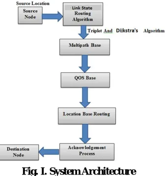
Our aim in this paper is to reduce this tradeoff between optimality and comfort of employment in routing. Also we are aimed to reduce the congestion in the transmission along with maintaining QoS in terms of increasing lifetime of portable nodes. [1] The packet must be destined to the multipath destination by using shortest path algorithm. Our paper proposes the different measures of quality of services and reduces the traffic overhead. It provides optimized solution and has a way to send the packets to the different destination that is multi destination. Not surprisingly, there are multiple challenges to overcome when designing such a solution. Before getting into them, we will look the proposed architecture for ease of exposition. The proposed architecture is shown in following figure I.
When the system starts, the sender acts as a source node by using link state routing principle sender sends packets to the destination which is a receiver. It receives the packets and then compute shortest path tree for destination using by Dijkstra’s shortest path algorithm. The information routers require to build their databases is provided in the form of Link State advertisement packets (LSAP) [3]. Routers do not advertise their entire routing tables; instead each router advertises only its information regarding immediately adjacent routers. Using java platform for developing the
Fig. I. System Architecture
send packets to the multiple destinations at the same time called multi destination .System is source routing system means source initiate the system.
By using the Link state routing and 2ACK algorithm we are trying to minimize the energy consumption requirement for the system and hence increasing the QoS. Also the packet is destined to the multipath destination by using shortest path algorithm which is explain as follows.
1) SHORTEST PATH ALGORITHM:-
For a given source vertex (node) in the graph, the algorithm finds the path with lowest cost (i.e. the shortest path) between that vertex and every other vertex. It can also be used for finding costs of shortest paths from a single vertex to a single destination vertex by stopping the algorithm once the shortest path to the destination vertex has been determined. For example, if the vertices of the graph represent cities and edge path costs represent driving distances between pairs of cities connected by a direct road, Dijkstra's algorithm [4] can be used to find the shortest route between one city and all other cities. As a result, the shortest path algorithm is widely used in network routing protocols, most notably IS-IS and OSPF (Open Shortest Path First).
Function Dijkstra(Graph, source):
dist[source] := 0 // Distance from source to source
for each vertex v in Graph // Initializations if v ≠ source
dist[v] := infinity // Unknown distance function from source to v previous[v] := undefined // Previous node in optimal path from source end if add v to Q // All nodes initially in Q (unvisited nodes) end for while Q is not empty: // The main
loop
u := vertex in Q with min dist[u] // Source node in first case remove u from Q for each neighbour v of u : // where v has not yet been removed From Q.
alt := dist[ u ] + length( u, v)
if alt < dist[ v ]: // A shorter path to v has been found
dist[v] := alt previous[v] := u end if
end for end while return
dist[], previous[] end function
2) 2ACK ALGORITHM
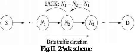
Fig.II. 2Ack scheme
Figure. II shows the working of the 2ACK scheme. Here, N1, N2, and N3 are three consecutive nodes (triplet) along a route. Link state routing protocol generates the route from a source node S, to a destination node D in its Route Discovery phase. Here N1 sends a data packet to N2 and N2 forwards it to N3, but N1 is unaware whether N3 receives the data packet successfully or not. Thus 2ACK scheme requires an explicit acknowledgment to be sent by N3 to notify N1 that data packet is received successfully. Thus when node N3 receives the data packet successfully, it sends out a 2ACK packet along with the ID of the corresponding data packet over two hops to N1 (i.e., in the opposite direction of the routing path as shown in fig.). To notation purpose, N1 in the triplet [N→N2→N3] is notified as the 2ACK packet
receiver and N3 as the 2ACK packet sender [3].
There may be more than one sets of triplet along the route. For every triplet such 2ACK transmission takes place. Thus only the first router from the source will not serve as a 2ACK packet sender. The last router just before the destination and the destination will not serve as 2ACK receivers.
The triplet N1 → N2 → N3 in Figure II illustrate 2ACK’s processing [5]. Note that such codes are run on each of the sender/receiver of the 2ACK packets. Following is the algorithm of our proposed system.
1) Start.
2) Sender is S and Destination is D.
3) Compute shortest path tree for destination D using HALO method.
4) Form new triplet N1 → N2 → N3 by taking 3 nodes from shortest path route.
5) N1 is considered as temp sender node and N3 as temp Receiver node and N2 is middle Node. 6) Packet is forwarded from N1 to N3.
7) N3 send acknowledgement to N1 using 2Ack. 8) Check if (N3= = D).
9) If not then repeat Step 4 to 8 for next 3 nodes. 10) If yes then D sends final acknowledgement to S. 11) Stop.
III.RELATED WORK
The architectural description consists of following modules which shortly explain below.
a. Network Node Configuration:-
b. Path Design:-
For the path design we are using [3] Link state routing protocol along with Dijkstra’s algorithm. The link state is routing protocol which is used to get the multiple routes from source to the destination. Among all routes the shortest route is been formed using Dijkstra’s shortest path algorithm and path is been finalized.
c. Sender and Receiver module:
The sender node is used to send the data along the path. The sender must send the data via intermediate nodes and wait for the acknowledgement. Each intermediate node also works as a sender and receiver. The receiver node receives the data packet and sends back
the positive acknowledgement to the source.
d. Link Management:-
Adapt split ratios dynamically and incrementally by decreasing along links that belong to nonshortest paths while increasing along the link that is part of the shortest path at every router. If instead split ratios are set to be positive instantaneously only to the links leading to shortest paths, then we get OSPF [2] with weights.
e. Multipath Routing:-
Multipath routing is a promising routing scheme to accommodate these requirements by using multiple pairs of routes between a source and a destination. Multipath routing is the routing technique of using multiple alternative paths through a network, which can yield a variety of benefits such as increased bandwidth, or improved security. The multiple paths computed might be overlapped, edge disjointed or node disjointed with each other. Extensive research has been done on multipath routing techniques.
IV.SYSTEM ANALYSIS
The experimental results are taken using 3 to 10 number of nodes in network. And data file from 1 MB to 100 MB transferred using both existing and proposed system. From these different results values are stored into database. By performing operations on database following graphs are plotted in application using JFree Charts. Following graphs are plotted.
Graph 1: Acknowledgement Comparison Graph
acknowledgements in existing system. This is the main objective of our proposed system. In wireless network reduction in the number of operations will lead to power saving.
Also proposed system is applied to both Link state routing protocol and DSDV. Following is the table of comparative analysis with different parameter for Link state routing and DSDV protocol.
V. EXPERIMENTAL RESULTS
Figures shows the results of the node selection of multi hop adaptive link state optimal routing in wireless ad hoc network. Fig 1. A. Shows the GUI page where the destination procedure should be continued. Fig B. Shows the whole nodes in the network also sending file as well as the receiving files.
(A) (B)
Fig. 2. It normally shows the sending and receiving history for the further communication which makes the selection of the path very easy(a) Send History (b) File receiving history
(c) Receiving window after sending from source node. It should be generate the path itself and forms the triplet nodes itself and makes the traffic rate of acknowledgement rate low.
Fig. 3 Following defines the DWT formulation for the image type of confidential data (a) Readings of Image after applying first DWT then Readings of Image after applying second DWT and final Resultant images.
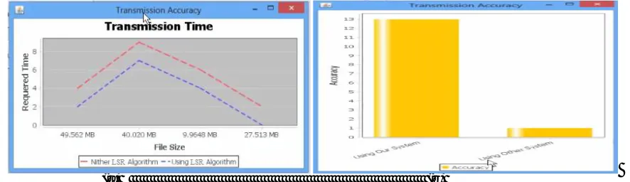
Fig. 4 Adaptive link state results shown here (a) Shows the transmission time regarding existing and the proposed system (b) Shows the accuracy regarding the transmission comparison for the system (c) Shows the Congestion Graph
regarding the existing system and our system
(a) (b)
The fig.4 a. describes the graph where the Link State Routing algorithm can take less time for transmitting the data as per its size where as the other routing algorithm should take more time than the Link state routing algorithm.
(c)
The fig.4 b. describes the comparison of the transmission of any type of data accuracy as per the transmission rate and the transmission time.
(c)
Fig 4. c. describes the data transmission rate as per the traffic and it shows the traffic rate should be too less bcause we are using the 2ACK scheme for reducing the acknowledgement of the system during source to destination
transmission of the data.
VI. CONCLUSION
There are so many limitations for the existing algorithms. Some of the techniques couldn’t find the best path for efficient data transferring. In other techniques, even though it is able to find the shortest path, there may be traffic or congestion during the packet transfer and that system are not designed for multi destination routing. Also there is no assurance that it will reach its destination and also QoS is not been the taken seriously. In our paper we are using shortest path algorithm followed by link state routing algorithm and they helps to find the best shortest path for data transfer with least cost. The packets will reach at the destination without any delay. Also traffic engineering is efficiently implemented which control traffic and thus congestion control mechanisms are also provided. This paper also provides efficient error controlling mechanisms. The proposed scheme is design to aim for multi destination along with providing highest QoS in terms of energy consumption. These features provide efficiency to the data transfer from source to destination.
REFERENCES
[1]Nithin Michael and Ao Tang, HALO: Hop-by-HopAdaptive Link-State Optimal Routing, IEEETRANSACTIONS ON NETWORKING, VOL. PP, 10SEPTEMBER,2014.
[2] N.Michael, A.Tang, and D.Xu, “Optimal link-statehop-by-hop routing,” in Proc. IEEE ICNP, 2013, pp.1–10.
[3] KushalHittanalli, Anitha R, “Improving the Efficiency and Obtaining Optimality in Link State Routing”, IJSRD, Vol. 3, Issue 01, 2015, ISSN (online): 2321-0613. [4] K. Liu, J. Deng, P. K. Varshney, and K. Balakrishnan, "An Acknowledgment-based Approach for the Detection of Routing Misbehavior in MANETs," IEEE Transactions on Mobile Computing, vol. 6, no. 5, pp. 536-550, May 2007.
[5]Liu Kejun, "Detecting Routing Misbehaviour In Mobile Ad Hoc Network" (2006), University of New Orleans Theses and Dissertations, Paper 1046, http://scholarworks.uno.edu/td.
[6] A. Elwalid, C. Jin, S. Low, and I. Widjaja, “MATE: MPLS adaptive traffic engineering”, in Proc. 20th Annu. IEEE INFOCOM, 2001, vol. 3, pp. 1300–1309. [7] R. Gallager, “A minimum delay routing algorithm using distributed computation,” IEEE Trans. Commun., vol. COM-25, no. 1, pp. 73–85, Jan. 1977. [8] WalidKrichene, “On Social Optimal Routing Under Selfish Learning” IEEE Trans. Commun., 2016.
[9] Yiftach Richter and ItsikBergel, “Optimal and Suboptimal Routing Based on PartialCSI in Wireless Ad-hoc Networks”,2015 IEEE 16th International Workshop on Signal Processing Advances in Wireless Communications (SPAWC).