NB-3650M FATIGUE CALCULATION PROCEDURE
Paul Smeekes1, Eero Torkkeli2, Mårten Perklén2 and Otso Cronvall3
1
Teollisuuden Voima Oyj, Olkiluoto, Finland ([email protected])
2
Insinööritoimisto FEMdata Oy, Espoo, Finland ([email protected])
3
VTT, Espoo, Finland ([email protected])
BACKGROUND AND GOAL
Fatigue is considered a significant long-term degradation mechanism for safety significant pressure equipment in nuclear power plants. The ASME Section III [1] procedure aims to prevent formation of fatigue cracks during the specified service period. Several studies performed in the USA and Japan indicated sihnificant environmental effects. This has yielded a methodology as described in the NUREG/CR-6909 [2] and the JSME S NF1-2006 [17]. From an analytical point of view the NB3600 (engineering approach) and NB3200 (detailed 3D analysis) fatigue analysis methodology and the one in the NUREG/CR-6909 (full time history) are not compatible. In the work presented here a methodology was developed to combine these methods.
The main reasons for the ASME NB-3650M (modified) procedure development are:
• The original design-lifetime is running out and will be extended (to 60 years). As reanalysis has to be done this was a good moment to look at the analysis methodology.
• As well for the RI-ISI procedure that is presently in use as for the coming probabilistic RI-ISI procedure it is necessary to determine the cumulative fatigue usage in such a way that cumulative usage factors are commensurate.
• In the classic ASME NB-3600 procedure only scalar stress differences are used and the actual time and location of the stress in the pipe cross section is lost. To study the influence of the coolant on fatigue a procedure was developed and documented in the NUREG CR/6909. This procedure uses the change of strain over the time and is thus not compatible with the classic procedure. To enable the best possible application of this procedure it was necessary to develop a strain based transient fatigue analysis procedure.
• As the operational record of the present plants in the world shows that low-cycle fatigue is not actually a problem the increase of conservatism due to the application of the NUREG CR/6909 procedure has to be partly covered by a reduction of the intrinsic conservatism in the classic NB3600 fatigue analysis procedure. To reach this goal application of a best estimate procedure is necessary.
The development, testing and validation was organized as follows:
• The actual method development was mainly done by FEMdata and TVO. At the beginning of the project there was some involvement of VTT and FORTUM.
• Programming was done by FEMdata [7] and [8] and tested by FEMdata, TVO and VTT. For the testing the feedwater system of the Olkiluoto plants was used [10] and [11].
• A comparison was made with an Inspecta analysis [16], the latter being more simplified.
• In a Master's Thesis the method was even applied with a full 3-D volume model [12].
• The new full transient stress analysis as well as the ASME NB-3650M procedure and the results for both have been validated by VTT [3], [4] and [5].
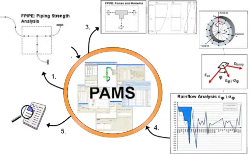
METHODOLOGY DESCRIPTION FOR ANALYSIS OF ONE CROSS SECTION
The main means to achieve the goal are described below:
1. Determine the full stress/strain time history at distinct locations around the circumference and both at the inside and outside of the pipe, see figure 1 and 2.
2. Determine the local temperatures, stresses and strains in all directions.
3. The tests on which the NUREG CR/6909 procedure is based were 1-D axial monotonic tests in constant temperature water. Obviously application is not straightforward. To approach the NUREG test situation in the distinct locations defined above the full fatigue analysis is performed separately for every requested angle , see figure 1.
4. Shear stresses have been fully taken into account in the determination of the true strains. True strain is here defined as the actual deformation of the material in a distinct direction. 5. The sign of tensional and compressive stress and strain components is taken into account
at all times and in all equations. In the classic ASME NB-3600 procedure the sign is lost but the sign is necessary for the NUREG CR/6909 procedure.
6. Stress indices are separately defined for all relevant stress directions and types and taken into account for the stress and strain component that is actually affected.
7. True strains are determined with analytical equations.
8. Fatigue strain cycles and associated time periods are determined with an adapted rainflow method.
9. The allowable number of cycles is directly obtained with help of the fatigue strain cycle. 10. Once looking in one direction only it is also possible to take the unidirectional
NUREG/CR-6909 procedure into account.
ANALYSIS PARAMETER SETTINGS
In the analysis the following parameters can be set:
Angle defining the number of points to be analyzed around the circumference circumferential output angle 0° … 360°, default step 30°, see figure 2.
Angle defining the directions to be analyzed angles between the angles 0° and 90° alternatively 0° and 180° in case range > 10, default step 15°, see figure 2.
fen: thermal stress resolution to save analysis time, as a default no time step may yield a
thermal stress change of more than 5 MPa.
IFEN: Fen method choice: J1, J2, V1 and V2. These different stress (J) and strain (V) based
fatigue analysis methods are later discussed in more detail.
Design fatigue curve selection: ASME, ANL, or user defined (in input data).
th: threshold value for strain amplitude, default from [1] (A-8) (A-13) (A-18)
psth+: strain increase to start Fen analysis, default same as for th
psth-: strain decrease to reset Fen,nom to 1, default psth- = psth+
SIGTOL ( tol): stress cycles with range less than tol omitted from fatigue analysis,
default 10 MPa.
IHIST10: ( constant over whole analysis, results for “most severe” are displayed) 0 load cycles calculated individually, usage factors (same ) are summed
1 calculation over plant history, best estimate for unidirectional fatigue
STRESS ANALYSIS
In the fatigue analysis first the nominal transient stresses due to internal pressure, moments and thermal loading are separately determined. Then these nominal stresses are multiplied by the applicable stress indices. Separate stress indices were defined for longitudinal and transverse welds and for the load cases internal pressure, moments and thermal loading [6]. These were defined with use of the stress indices from [2] table NB-3681 (a)-1. For different locations around the circumference different sets of stress indices can be defined, see figure 2. In case for instance the weld does not coincide with a transition of the cross section different analysis can be defined for these cross-sections. After being multiplied with the stress indices the stresses are used to determine the stress time histories and strain time histories in the locations requested. In these locations the fatigue is separately determined in every direction , see figure 2, with help of the following equations:
= ½ ( axial + hoop) + ½ ( axial hoop) cos(2 ) + ½ sin(2 )
= ½ ( axial + hoop) + ½ ( axial hoop) cos(2 ) + sin(2 )
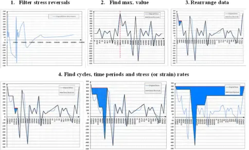
RAINFLOW METHOD G
As a starting point both rainflow methods CEN/TC147/WG2 N23 (ISO) and ASTM E1049-85 were investigated. These methods give the same stress and strain cycles but the time information of the cycle is lost. This is a problem with regard to the application of the NUREG CR/6909 procedure that requires a strain based integration over the time. Therefore, based on the aforementioned methods, an adapted method called method G was developed, see figure 3 below.
STRESS BASED METHODS J0, J1 AND J2
Stress cycles are determined with the classic rainflow method CEN/TC149
• J0: Fen = 1, environmental effects are not taken into account. Stress cycles and associated time steps with rainflow analysis procedure G
• J1: Feni is determined for the whole load cycle i and used for all of its stress cycles m
• J2: Feni-m is determined for every stress cycle m based upon the time spans from the rainflow analysis procedure G.
Strain / Fen Method J1, J2
Stress intensity Equations used in the flowchart
j
S12 = (Inner surface and Fen)
S12 = - +90 in case the sign of
and +90 is different
S12 = ( rad 0)
S12 = - +90
hoop S23 = shoop - sradial (Same as s90 - srad ) S23 = 90 - rad
axial S31 = sradial - saxial (Same as srad - s0 ) S31 = rad - 0
Table 1, Determination of S12, S23 and S31 for thestress based methods J0, J1 and J2
STRAIN BASED METHODS V1 AND V2
Strain cycles and associated time steps are determined with rainflow analysis procedure G. At present the strain based methods are used for Fen-analysis:
• V1: Feni is determined for whole load cycle i and used for all of its strain cycles m
• V2: Feni-m is determined for every strain cycle m based upon the time spans from the rainflow analysis procedure G.
Strain / Fen Method V1, V2: Strain intensity,
only when Fen is computed Equations used in the flowchart
axial S31 = axial × E S31 = 0 × E
hoop S23 = hoop × E S23 = 90 × E
j S12 = j × E ( rad 0) S12 = j × E ( rad 0)
DETERMINATION ON THE FEN
The following definitions are used:
• Fen,k Instantaneous Fen factor (Fen,nom in [1])
• Fen,r Fen factor for strain rise r
• Fen, _m Fen factor for stress cycle m
• Fen, _i Fen factor for load cycle i
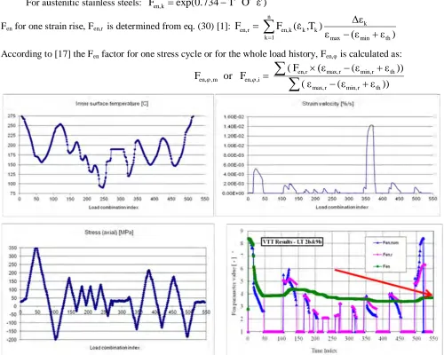
The main steps of the Fen computations for the considered strain history are computation of Fen,k values, computation of Fen,r values and finally computation of final Fen values Fen, _m or Fen, _i. The instantaneous Fen,k value for a time step k and time interval t1 . . . t2 is calculated with the
NUREG/CR-6909 Appendix A Equations (A.2) ... (A.18), where:
Strain increase k = 2 1
Strain rate k = k /(t2 t1) > 0
Inner surface temp. Tk = max[ T1, T2]
Dissolved oxygen level Ok = max[ O1, O2]
Sulfur content S
For austenitic stainless steels: Fen,k exp(0.734 T O )
Fen for one strain rise, Fen,r is determined from eq. (30) [1]:
)
)
T
,
(
F
F
th min max k k n 1 k k k en, r en,According to [17] the Fen factor for one stress cycle or for the whole load history, Fen, is calculated as:
)) ( ( )) ( F ( F or F th r min, r max, th r min, r max, r en, i , en, m , en,
RESULT PRESENTATION
Below some results are summarized for the ASME NB-3650M cumulative usage factor analysis for Node ID 69 (Weld1.312-3 9B) and for Method V2. Cumulative usage factor is calculated for each circumferential angle , at inside/outside surface and for direction angle :
Below a more detailed result listing for the ASME NB-3650M total usage factor calculation for Node ID 69 (Weld1.312-3 9B) and for Method V2: Circumferential angle = 150°, Inside surface, Stress Intensity S12, Direction angle = 0° is presented.
FUTURE DEVELOPMENT
In the future the following items will be studied:
1. Simplify and improve the consistency in the determination of the stress intensities, as well with regard to the procedure used as to the type of fatigue testing behind the procedure.
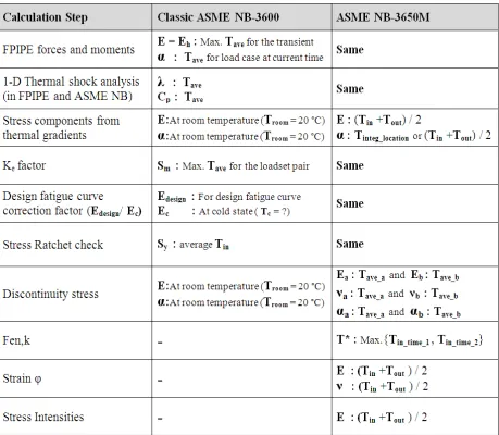
2. Investigate the influence of the temperature used in the different parts of the different analysis steps to make the use of the temperature as consistent as possible, see table 3 below.
Table 3, Influence of the temperature used in the different parts of the different analysis steps
CONCLUSIONS
The system is now taken into use and compared with elder analyses without Fen. The increase of the cumulative usage is moderate depending on the chosen analysis method. The most consistent method is method V2. This is a consistent strain based method that determines the Fen for every separate strain cycle. Comparison between the classic method and the V2 method showed that increase appears only in a few locations. The number of performed analyses is however not yet large enough to draw any general conclusions. It seems that the extra overconservatism induced by the NUREG/CR-6909 is compensated by the more accurate and less overconservative analysis by the new methodology. When looking at the low cycle fatigue induced crack records in the nuclear world this is a good thing.
List of references
[1] Chopra, O., K., Shack, W., J. Effect of LWR Coolant Environments on the Fatigue Life of Reactor Materials. NUREG/CR-6909, Final Report. U.S. Nuclear Regulatory Commission (NRC), February 2007
[2] ASME Boiler and Pressure Vessel Code Section III, Division 1, Article NB-3600. 2004 Edition. [3] VTT-R-06000-10, Rev. 0, 28.12.2010, Cronvall Otso, VTT,
Validation of Fatigue Analysis Procedure NB-3650M
[4] VTT-R-VTT-CR-00467-12-11, Rev.1, 16.1.2012, Cronvall Otso, VTT, Validation of Fatigue Analysis Procedure NB-3650M, Research Report
[5] VTT-R-03375-11, Rev. 2, 6.5.2011, Cronvall Otso, VTT,
OL1 and OL2 - Piping Component Analyses: Stress Analysis Procedure and Input Data Treatment
[6] OL1-TVO-ASME-STRESS-INDICES, Rev. C, 23.6.2010, Komulainen Esa, SWECO Industry Oy,
OL1/OL22, evaluation of stress indices for class 1 piping analyses
[7] GS-FDT-TVO-ASMENB-110927, FEMdata Oy, FPIPE ASME Postprocessor, Reference Manual.
[8] GS-FDT-TVO-ASMENB-110505, FEMdata Oy, FPIPE ASME Postprocessor, User Manual.
[9] EPRI-TR-107533, October 1998, Carter R., EPRI. An Improved Approach for Performing Simplified Elastic-Plastic Fatigue Analysis. Report
[10] Transient analysis report for the 312/327/321 system [11] Fatigue analysis report for the 312/327/321 system
[12] RP-TVO-TVO-T0360-110224, Rev. 1, 2.9.2011, Lemettinen Petri, TVO, Automatic Detailed 3-D Fatigue Analysis of Structural Parts in a Piping System.
[13] Engineering thesis, BA-TVO-VALO-PAMS-100901, Rev. 0, 1.9.2010, Valo Jani, TVO, Dokumentaatioautomaatti
[14] Engineering thesis, BA-TVO-SANT-PAMS-111006, Sami Santamaa. Document maker.
[15] Sami Santamaa, TVO. Document maker user manual.
[16] 2011:04, Strålsäkerhetsmyndigheten, Strömbro Jessica, Evaluation of the Technical Basis for New Proposals of Fatigue Design of Nuclear Components, Report.
[17] JSME S NF1-2006, Rev. 0, 1.3.2006, The Japan Society of Mechanical Engineers, Codes for Nuclear Power Generation Facilities - Environmental Fatigue Evaluation Method for Nuclear Power Plants