Analysis of T-Shape Footing On Layered
Sandy Soil
Gargi V. Kulkarni
1, Prof. S. W. Thakare
2P.G. Student, Department of Civil Engineering, Govt. College of Engineering, Amravati, Maharashtra, India1
Associate Professor, Department of Civil Engineering, Govt. College of Engineering, Amravati, Maharashtra, India2
ABSTRACT: While designing a foundation, Bearing capacity and settlement are two main factors considered. In addition to the vertical settlement, inclined and eccentric loading may result in horizontal displacement (and sliding) and/or rotation (or over-turning), which can reduce the ultimate bearing capacity and increase the settlement. In such cases, either properly designed conventional footing may be provided or ground improvement technique may be adopted. A T-shaped footing can be used to improve the bearing capacity of footing against the action of inclined and eccentric load. In natural conditions, the soil is not homogeneous in all directions. Hence, in this paper, the behaviour of a T-shaped footing is analysed on layered sand subjected to vertical centric, eccentric and inclined load using Finite element method of analysis; PLAXIS-2D software, and the results are deduced to study the improvement in bearing capacity of T-shaped footing as compared to that of conventional strip footing.
KEYWORDS:T-shaped footing, Layered sand, PLAXIS-2D I. INTRODUCTION
Foundation is an important part of any structure. The conventional method of footing design requires sufficient safety against failure and the settlement must be kept within the allowable limit. Footings of retaining walls, abutments of bridges, industrial machines, and portal framed buildings are not only subjected to vertical or inclined loads but also to eccentric loads. In such cases, either properly designed conventional footing may be provided or ground improvement technique may be adopted. Another alternative is to adopt T-shaped footing to improve the bearing capacity of footing against the action of inclined and eccentric load. T-shaped footing is a strip footing provided with vertical cutoff. The T-shaped is a footing used to improve the bearing capacity of shallow footings against the action of eccentric loads. The vertical insertion of the rigid T-shaped footing, into the soil, provides considerable resistance, against both sliding and overturning, enough to regain the reduction in bearing capacity and the increase in settlement.
II. LITERATUREREVIEW
The study regarding the behaviour of various types of foundations in layered soil has been carried out numerically, analytically and experimentally by various authors. These works are reviewed keeping in view the methodology, principles, and various aspects of experimental or analytical behaviour of footing on bearing capacity and settlement analysis. Based on the literature review, the gap in the research work is identified to carry out further research work to form the basis for the present work.
1. In one of the studies by Alhassan et al. (2012) [1], it was observed that in the case of foundations with T-shape vertical cross-section, both soil along the trunks and bases of the foundation vertically deformed. This indicated that using foundations with T-shape vertical cross-section can help in mobilizing substantial mass of soil above the foundation base, to function not only as surcharge to the soil below the foundation base, but also in resisting loads, and therefore assisting in the distribution of structural load to less dipper soil strata, especially when stronger soil layers is underlain by weaker ones.
2. Kaya et al. (2013) [2]presented the results of experimental work on T-shaped footing. Experimental studies were performed to investigate the effect of load eccentricity on the loose sand the dense sand. It was concluded that load bearing capacity increased with the increase in the insertion depth. Results from numerical and experimental analysis were compared, and it was noticed that obtained results were similar.
3. Dr. Mahiyar et al. (2015) [3] carried out experimental studies to study the behaviour of T shaped footing under eccentric loading. After carrying out a total of 144 experiments and calculating the tilt in different cases, it was found that bearing capacity increased for eccentricity ratio up to 0.2, after that it started decreasing and bearing capacity increased with depth of insertion.
4. Thakare and Kapase(2015) [4] analysed the behaviour of T shaped footing subjected to eccentric and inclined loading. Various parameters like effect of eccentricity, effect of inclination of load, effect of depth of insertion cut off and effect of inclination of insertion cut off were studied using PLAXIS 2D. It was concluded that bearing capacity increased with the increase in the depth of insertion cut-off and reached its optimum value at insertion depth equal to 0.6 times the width of footing, bearing capacity increased with increase in the angle of insertion cutoff with vertical, more predominantly up to 15˚ and bearing capacity ratio increased with increase in eccentricity ratio and inclination of applied load.
5. Zhu et al. [5]studied the Bearing capacity of rectangular footing with strong clay over weak clay using finite element analysis ABAQUS 3D. Strength ratio and thickness ratio were varied. It was concluded that the bearing capacity was reduced due to presence of weak clay beneath strong clay and also was affected due to strength ratio (c1/c2) and thickness ratios (H1/b); the shape factor was weakly dependent on the depth and
bearing capacity factor increased with depth ratio.
6. Abdelmegeed Kabasy Mohamed(2012) [6] performed numerical analysis using PLAXIS 2D to study the behaviour of strip footing on sand in the existence of a buried rock. The effect of rock position and depth is analysed under the strip footing. The final results showed that the stresses under the strip footing have increased by 40%, when rock is encountered under the middle of the footing at depth D = 0.5m
III. NUMERICAL MODELLING
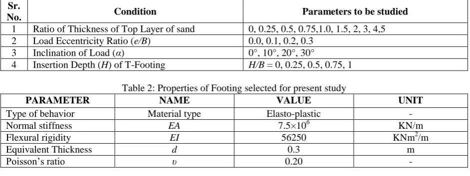
The analysis in present research work was carried out using PLAXIS-2D which works on Finite Element Method. The T-shaped footing of width 1.0 m was modelled as a rigid plate and was considered to be very stiff and rough in the analysis. The soil was modelled using Mohr Coulomb model and elasto-plastic behaviour of footing was adopted. Fig. 1 shows the typical T-shaped footing with various parameters selected for analysis.
Fig. 1: A T-Shape Footing with Various Parameters Selected for Analysis in the Present Study
The symbols used were, Depth of top sand layer (Ds1), Depth of bottom sand layer (Ds2), Width of Footing (B), Height
of insertion cut-off (H), Eccentricity (e), Angle of inclination of loading (α) and Load (P).The parameters varied are shown in Table 1.The properties of sand selected were as shown in Table 2.The properties of footing selected were as shown in Table 3.
Table 1: Parameters Varied in the present study Sr.
No. Condition Parameters to be studied
1 Ratio of Thickness of Top Layer of sand 0, 0.25, 0.5, 0.75,1.0, 1.5, 2, 3, 4,5 2 Load Eccentricity Ratio (e/B) 0.0, 0.1, 0.2, 0.3
3 Inclination of Load (α) 0°, 10°, 20°, 30°
4 Insertion Depth (H) of T-Footing H/B = 0, 0.25, 0.5, 0.75, 1
Table 2: Properties of Footing selected for present study
PARAMETER NAME VALUE UNIT
Type of behavior Material type Elasto-plastic -
Normal stiffness EA 7.5×10⁶ KN/m
Flexural rigidity EI 56250 KNm2/m
Equivalent Thickness d 0.3 m
Table 3: Properties of sand selected for present study
Properties Symbols Values Values
Soil model Mohr Coulomb Model Mohr Coulomb Model
Soil type Loose sand Dense sand
Unit weight γ 14 kN/m³ 18 kN/m³
Friction angle ɸ 32° 41°
Dilatancy angle ψ 2° 11°
Poisson’s ratio μ 0.3 0.3
Young’s Modulus E 30×103 kPA 80×103 kPA
III.RESULTSANDDISCUSSIONS
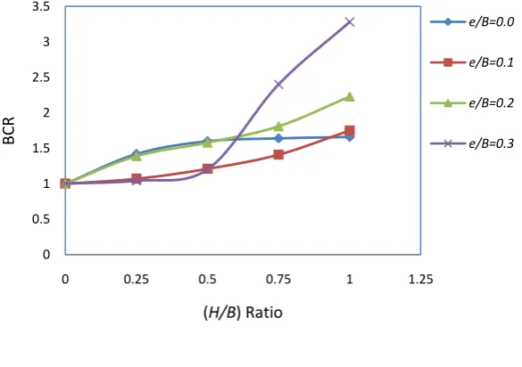
Analysis of T-shape footing, placed on loose sand bed, dense sand bed and multilayered sand bed, subjected to vertical centric loading, vertical eccentric loading and inclined centric loading was performed using PLAXIS-2D software. The results were interpreted in the form of Bearing Capacity Ratio (BCR). BCR is the ratio of ultimate bearing capacity of T-shape footing to the ultimate bearing capacity of strip footing for similar conditions of loading and soil bed. The results are discussed below.
a) Effect of Depth of Insertion Cut-off
In case of T-shape footing placed on loose sand bed, subjected to vertical eccentric loading, as shown in Fig. 2 (a), it is seen that the increase in BCR is much higher in case of footing with H/B ratio greater than 0.5 and subjected to eccentric loading with higher eccentricity ratio.
(a)
Fig. 2(a): The variation of BCR with respect to Insertion Depth Ratio (H/B) for various Eccentricity Ratios (e/B) and load inclinations (α) on loose sand bed
0 0.5 1 1.5 2 2.5 3 3.5
0 0.25 0.5 0.75 1 1.25
BC
R
(H/B) Ratio
e/B=0.0
e/B=0.1
e/B=0.2
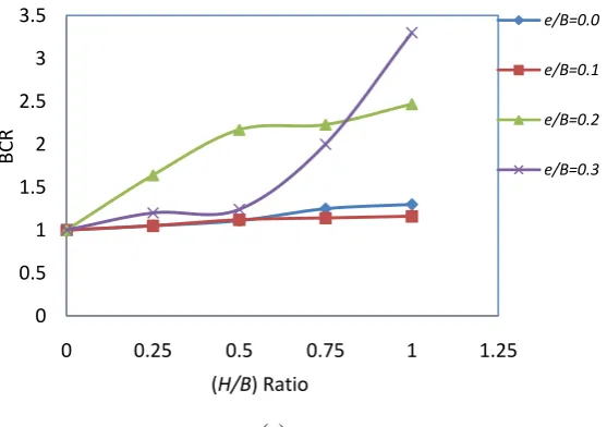
In case of T-shape footing placed on loose sand bed, subjected to an inclined centric loading, results are shown in Fig. 2 (b), it is seen that BCR increases with increase with H/B Ratio up to 0.5. Thereafter, the increase in BCR is marginal with further increase in H/B Ratio.
(b)
Fig. 2(b): The variation of BCR with respect to Insertion Depth Ratio (H/B) for various Eccentricity Ratios (e/B) and load inclinations (α) on loose sand bed
In case of T-shape footing on dense sand bed subjected to vertical eccentric loading and inclined centric loading, results are shown in Fig. 3 (a) and 3 (b) respectively. From the Figure 3 (a), it is seen that, the increase in BCR is much higher in case of footing with H/B ratio greater than 0.5 and subjected to eccentric loading with higher eccentricity ratio.
(a)
Fig.3(a): The variation of BCR with respect to Insertion Depth Ratio (H/B) for various Eccentricity Ratios (e/B) and load inclinations (α) on dense sand bed
0 1 2 3 4 5 6 7 8
0 0.25 0.5 0.75 1 1.25
BC
R
(H/B) Ratio
a=0
a=10
a=20
a=30
0 0.5 1 1.5 2 2.5 3 3.5
0 0.25 0.5 0.75 1 1.25
BC
R
(H/B) Ratio
e/B=0.0
e/B=0.1
e/B=0.2
From the Figure 3(b), it is seen that BCR increases with increase in H/B Ratio up to 0.75. Thereafter, the increase in BCR is marginal with further increase in H/B Ratio. Thus, when T-shape footing is placed on a dense sand bed and subjected to an inclined centric loading, the optimum height of insertion cut-off may be considered as 0.75 times the width of footing.
(b)
Fig. 3(b): The variation of BCR with respect to Insertion Depth Ratio (H/B) for various Eccentricity Ratios (e/B) and load inclinations (α) on dense sand bed
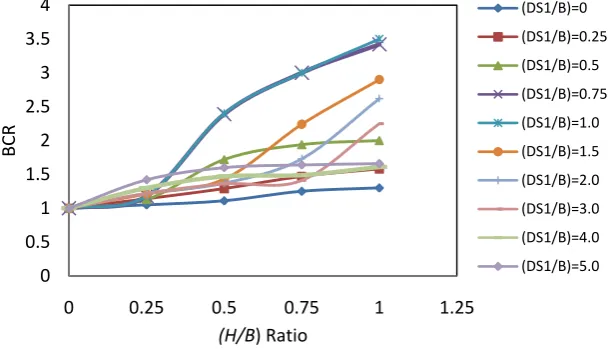
The effect of depth of insertion cut-off when T-shape footing is placed on multilayered sand bed and subjected to vertical centric loading is shown in Fig. 4 for layered sand bed with loose sand over dense sand layer.
Fig. 4: The variation of BCR with respect to Insertion Depth Ratio (H/B) for vertical centric loading on layered Sand bed of loose sand over dense sand bed
From the above Fig. 4, it is seen that variation of BCR with respect to insertion depth ratio (H/B) for vertical centric loading on layered sand bed of loose sand over dense sand bed , the BCR increases substantially with increase in the
0 0.5 1 1.5 2 2.5 3
0 0.25 0.5 0.75 1 1.25
B
C
R
(H/B) Ratio
a=0.0 a=10 a=20 a=30
0 0.5 1 1.5 2 2.5 3 3.5 4
0 0.25 0.5 0.75 1 1.25
BC
R
(H/B) Ratio
(DS1/B)=0
(DS1/B)=0.25
(DS1/B)=0.5
(DS1/B)=0.75
(DS1/B)=1.0
(DS1/B)=1.5
(DS1/B)=2.0
(DS1/B)=3.0
(DS1/B)=4.0
H/B ratio greater than 0.5 for DS1/B ratios 0.75 to 3. Whereas, for DS1/B ratio of 0, 0.25, 0.5, 4 and 5, the increase in
BCR with increase in H/B ratio is thus up to 0.75.The increase in BCR is however marginal.
Thus, in general, it may be concluded that the optimum H/B ratio for T-shape footing on a sand bed, either of loose or dense sand, or multilayer sand bed, the optimum height of insertion cut-off may be considered as 0.75 times the width of footing.
b) Effect of Layering of Sand Bed
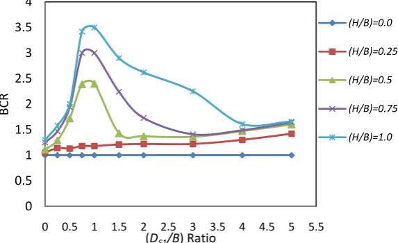
The variation of BCR with respect to depth of top layer of sand bed in case of multilayered sand bed of loose sand over dense sand bed and when T-shape footing is subjected to vertical centric loading is shown in Fig. 5.
Fig.5: Variation of BCR for centric loading on T-shape footing with respect to DS1/B Ratio on layered sand bed of
Loose sand over dense sand layer
From the above Fig.5, it is seen that, for H/B ratio 0 and 0.25, the BCR increases marginally with increase in DS1/B
ratio. Whereas, for H/B ratio ≥ 0.5, BCR increases significantly with increase in DS1/B ratio up to 1.0, thereafter, BCR
decreases with further increase in DS1/B ratio.
Therefore, it may be concluded that the T-shape footing supported on multilayered sand bed, gives better results when the depth of top layer of sand bed is equal to width of footing. Also if the height of insertion cut-off is kept equal to the width of footing, maximum BCR is obtained.
c) Effect of Eccentricity of Loading
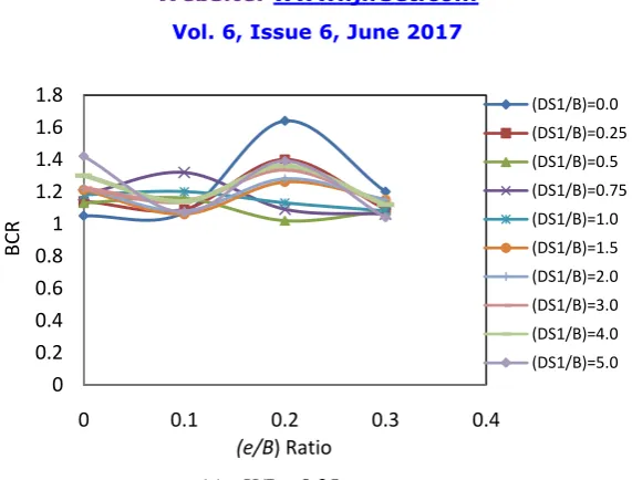
The variation of BCR with respect to eccentricity ratio of loading on shape footing is shown in Fig. 6, when the T-shape footing is placed on multilayered sand bed of loose sand over dense sand bed with varying insertion cut-off. In Fig. 6(a), it can be seen that the maximum BCR is obtained when the T-shape footing with H/B = 0.25 is subjected to load of eccentricity ratio 0.2.
0 0.5 1 1.5 2 2.5 3 3.5 4
0 0.5 1 1.5 2 2.5 3 3.5 4 4.5 5 5.5
BC
R
(DS1/B) Ratio
(H/B)=0.0
(H/B)=0.25
(H/B)=0.5
(H/B)=0.75
(a) H/B = 0.25
Fig. 6(a): Variation of BCR of T-shape footing on multilayered sand bed with respect to (e/B) Ratio for (H/B) =0.25
In Fig. 6(b), it can be seen that there is a variation in BCR with increase in eccentricity ratio and increasing thickness of top layer of sand. There is a marginal increase in the BCR when DS1/B ratio is ≥ 1.5.
(b) H/B = 0.5
Fig. 6(b): Variation of BCR of T-shape footing on multilayered sand bed with respect to (e/B) Ratio for H/B = 0.5
From Fig. 6(c), it can be seen that there is an increase in BCR when the H/B ratio is 0.75 and depth of top layer of sand
DS1/B ratio is 0.25 and 0.5. In this case, maximum BCR is observed when the footing is subjected to an eccentric load
of e/B ratio 0.3.
0 0.2 0.4 0.6 0.8 1 1.2 1.4 1.6 1.8
0 0.1 0.2 0.3 0.4
BC
R
(e/B) Ratio
(DS1/B)=0.0 (DS1/B)=0.25 (DS1/B)=0.5 (DS1/B)=0.75 (DS1/B)=1.0 (DS1/B)=1.5 (DS1/B)=2.0 (DS1/B)=3.0 (DS1/B)=4.0 (DS1/B)=5.0
0 0.5 1 1.5 2 2.5 3
0 0.1 0.2 0.3 0.4
BC
R
(e/B) Ratio
(c) H/B = 0.75
Fig. 6(c): Variation of BCR of T-shape footing on multilayered sand bed with respect to (e/B) Ratio for H/B ratio =0.75
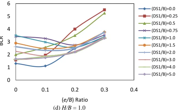
From Fig. 6(d), it can be seen that there is a phenomenal increase in BCR when the H/B ratio is 1.0 and depth of top layer of sand is DS1/B = 0.25.In this case, maximum BCR is observed, when footing is subjected to an eccentric loading
of e/B ratio 0.3.
(d) H/B = 1.0
Fig. 6(d): Variation of BCR of T-shape footing on multilayered sand bed with respect to (e/B) Ratio for (H/B) = 1.0
From above figures, it is seen that, for H/B ratios 0.25 and 0.5, BCR increases with increase in e/B ratio up to 0.2, thereafter, the BCR decreases with increase in e/B ratio. Whereas, for H/B ratios 0.75 and 1.0, BCR increases with increase in e/B ratio.
0 1 2 3 4 5 6
0 0.1 0.2 0.3 0.4
BC
R
(e/B) Ratio
(DS1/B)=0.0
(DS1/B)=0.25
(DS1/B)=0.5
(DS1/B)=0.75
(DS1/B)=1.0
(DS1/B)=1.5
(DS1/B)=2.0
(DS1/B)=3.0
(DS1/B)=4.0
(DS1/B)=5.0
0 1 2 3 4 5 6
0 0.1 0.2 0.3 0.4
B
C
R
(e/B) Ratio
Therefore, it may be concluded that for a T-shape footing on multilayered sand bed, subjected to eccentric loading, if the height of insertion cut-off is equal to the width of footing, optimum BCR is obtained. A T-shape footing with H/B ratio 1.0 is more advantageous if the eccentricity ratio (e/B) of load is 0.2.
BCR is maximum if thickness of top layer of sand is 0.25 times the width of footing, for footing placed on layered sand bed of loose sand over dense sand bed.
d) Effect of Load Inclination
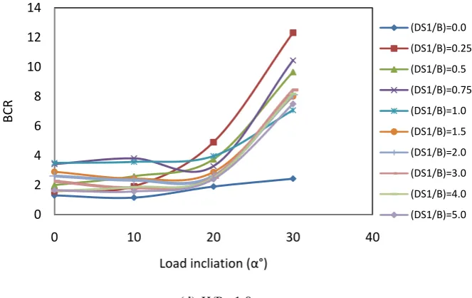
In case of multilayered sand bed, the effects of load inclination are plotted for T-shape footing on layered sand bed of loose sand layer over dense sand, as shown in Fig. 7 (a) to (d), for various H/B ratios. In Fig. 7 (a), it can be seen that there is a phenomenal increase in BCR when thickness of top layer of sand is 0.25 m.
(a) H/B = 0.25
Fig. 7 (a): Variation of BCR of T-shape footing with respect to load inclination for H/B = 0.25
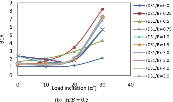
It can be seen in Fig. 7 (b) that there is a phenomenal increase in BCR when the thickness of top layer of sand (DS1/B)
is 0.25 and subjected to an inclined load of 30°.
(b) H/B = 0.5
Fig. 7 (b): Variation of BCR of T-shape footing with respect to load inclination for H/B ratio = 0.5 0
0.5 1 1.5 2 2.5 3 3.5 4
0 10 20 30 40
BC
R
Load incliation (α°)
(DS1/B)=0.0
(DS1/B)=0.25
(DS1/B)=0.5
(DS1/B)=0.75
(DS1/B)=1.0
(DS1/B)=1.5
(DS1/B)=2.0
(DS1/B)=3.0
(DS1/B)=4.0
(DS1/B)=5.0
0 1 2 3 4 5 6 7 8 9
0 10 20 30 40
BC
R
Load incliation (α°)
From Fig. 7(c), it can be seen that the BCR increases prominently for DS1/B ratios 0.25 and 0.5, for other points,
the increase in BCR is marginal. In this case, for all DS1/B, ratios maximum BCR is obtained when the footing is
subjected to an inclined load of 30°.
(c) H/B = 0.75
Fig. 7 (c): Variation of BCR of T-shape footing with respect to load inclination for H/B ratio = 0.75
From Fig. 7(d), it can be seen that the BCR is maximum at DS1/B ratio 0.25, with load inclined at 30°. With further
increase in DS1/B ratio .the increase in BCR was marginal. For all DS1/B ratios, BCR is maximum when subjected to
inclined load at 30°.
(d) H/B =1.0
Fig. 7 (d): Variation of BCR of T-shape footing with respect to load inclination for (H/B) ratio = 1.0 0
2 4 6 8 10 12
0 10 20 30 40
BC
R
Load incliation (α°)
(DS1/B)=0.0
(DS1/B)=0.25
(DS1/B)=0.5
(DS1/B)=0.75
(DS1/B)=1.0
(DS1/B)=1.5
(DS1/B)=2.0
(DS1/B)=3.0
(DS1/B)=4.0
(DS1/B)=5.0
0 2 4 6 8 10 12 14
0 10 20 30 40
BC
R
Load incliation (α°)
(DS1/B)=0.0
(DS1/B)=0.25
(DS1/B)=0.5
(DS1/B)=0.75
(DS1/B)=1.0
(DS1/B)=1.5
(DS1/B)=2.0
(DS1/B)=3.0
(DS1/B)=4.0
From the above figures, it is seen that, BCR increases with increase in load inclination angle greater than 20°.Thus, T-shape footings are particularly advantageous when subjected to centric loads inclined at angles greater than 20°.
Hence, it may be concluded that, for a T-shape footing on multilayered sand bed subjected to an inclined loading, maximum BCR is obtained if the height of insertion cut-off is equal to the width of footing. The insertion cut-off of H/B ratio 1.0 is particularly advantageous if the centric load is inclined at an angle of 30°.
In case of multilayered sand bed, when T-shape footing is placed on layered sand bed of loose sand over dense sand, the BCR is maximum if the thickness of top layer of sand is 0.25 times the width of footing.
IV.CONCLUSIONS
The dissertation work was carried out to study the performance of T-shaped footing subjected to vertical centric loads, vertical eccentric loads and inclined centric loads, using PLAXIS 2D, by considering the effect of depth of insertion cut-off for different load inclination angles and eccentricity ratios, on loose sand bed, dense sand bed and layered sand bed.
Based on the results of the present study, the following conclusions are drawn.
1. For T-shape footing on a sand bed, either of loose or dense sand, or multilayer sand bed, the optimum height of insertion cut-off may be considered as 0.75 times the width of footing.
2. The T-shape footing supported on multilayered sand bed, gives better results when the depth of top layer of sand bed is equal to width of footing. Also if the height of insertion cut-off is kept equal to the width of footing, maximum BCR is obtained in this case.
3. A T-shape footing on multilayered sand bed of loose sand bed over dense sand bed, subjected to eccentric loading, if the height of insertion cut-off is equal to the width of footing, optimum BCR is obtained. A T-shape footing with H/B ratio 1.0 is more advantageous if the eccentricity ratio (e/B) of load is 0.2.
4. In case of a T-shape footing on a layered sand bed, subjected to an inclined or eccentric load, BCR is maximum when the thickness of top layer is 0.25 times the width of footing.
5. For a T-shape footing on layered sand bed of loose sand bed over dense sand bed, subjected to an inclined loading, maximum BCR is obtained if the height of insertion cut-off is equal to the width of footing. The insertion cut-off of H/B ratio 1.0 is particularly advantageous if the centric load is inclined at an angle of 30°.
REFERENCES
[1] M.Alhassan I. L.Boiko. “Experimental Study of the Effect of Foundation Shape on the Deformation of Soils”, International Journal of Applied Science and Technology Vol. 2 No. 9; November 2012.
[2] Nihat Kaya and Murat Ornek. “Experimental and Numerical Studies of T-Shaped Footings”, Acta Geotechnical Slovenica,, Vol.1 No.5, pp.43- 54, 2013.
[3] Sunil Kumawat and Dr. Hemant K. Mahiyar. “Experimental Study on Tee Shaped Footing under Eccentric Vertical Loading”, International Journal for Scientific Research & Development| Vol. 2, Issue 11, pp 489-494, 2015 | ISSN (online): 2321-0613.
[4] Prof.S.W.Thakare and S.Kapase. “Performance of T-Shaped footing subjected to inclined and eccentric load”. IGC 2015, submission No. 332, 2015.
[5] Zhu M. and Michaoski R. L., (2010), “Bearing Capacity of Rectangular Footing on Two layer Clay”, American Society of Civil Engineers, Vol.191 No.15, pp. 997-1000, 2010.