Transformer Shunt Fault Detection using Two
Techniques
Swathy Sasikumar 1, Dr. V. A. Kulkarni 2
P.G. Student, Department of Electrical Engineering, Government College of Engineering, Aurangabad, Maharashtra, India1
Associate Professor, Department of Electrical Engineering, Government College of Engineering, Aurangabad,
Maharashtra,India2
ABSTRACT: Throughout the decades transformer has become a vital part of our power system. Thus any failure or disturbance in its operation may lead to further disruption of power. They have become far complex to model these days in terms of accuracy. These days due to varied reasons, mainly short circuit faults, the transformer failures have increased excessively. For this reason and so as to predict the faults before their occurrence the modeling of transformers becomes imperative. This paper discusses the numerous reasons for transformer deterioration. Also it discusses the techniques used for condition monitoring of the transformer. In addition to this two methods for detection of fault in the transformer are implemented.
KEYWORDS:Comparison, Condition monitoring, Frequency response, Stresses, Transformer failures.
I. INTRODUCTION
The growing times have seen a tremendous development in the power systems. The transformer has now become a vital part of the power system. The basic requirement of any electrical system is operation without any interruption. For the adequate as well as trustworthy operation of the transformer some consideration needs to be given to the causes leading to the failure of transformer. The varied reasons which may lead to the failure in a transformer may be the effect of the tensions acting on the transformer. These tensions can be categorized as electric, electromagnetic, insulating, thermal and chemical. These tensions on the transformer affect the various parts of the transformer and either one or a combination of more than one of these tensions may lead to the failure of transformer. The failures may sometimes be disastrous and altogether lead to severe damage. A power system being reliable is a crucial necessity for the performance of the power system. The utility as well as the consumers can be widely affected in terms of monetary expenditures due to the prolonged loss of power. Approximately 2% [1] of the total transformers that have been in service fail every year. The transformer failure is sometimes for the long haul as the means for maintenance is limited on some sites [1], [2].Also the replacing in such cases becomes difficult due to its size, accessibility of auxiliary transformer as well as additional cost of a new transformer. Therefore the utilities have an obligation of adapting new methods to establish a proficient maintenance approach with minimum mishandling of the equipment.
This paper studies the numerous reasons for transformer failures as well as the diagnostic techniques that have been adapted to detect certain types of failures. It discusses the advantages of some techniques over the other. A healthy transformer is also modeled and compared to faulty condition in the transformer. The results of these are discussed briefly. The frequency response in a healthy as well as faulty situation is compared and its nature is observed.
II. TRANSFORMER FAILURE
Enhancing the reliability
Preventing harm on transformer and loss in power Introduction of condition based approach
On occurrence of fault in a transformer it becomes necessary to detect the type of fault and reduce the repair time predominantly where continuous supply is essential. To limit the damage caused due to the failure of transformer on the system swift recognition of fault and monitoring the transformer condition becomes obligatory.
The main reasons for failure of transformers are considered to be the faults that are occurring within the transformer or most commonly they are called as incipient faults. This can be proved by the various surveys that have been conducted throughout the decades [1], [3], [4], [5].
The percentage failure rate along with the component where the failure occurs is given in Fig.1.From the bar graph it is clear that the percentage of failures due to winding and core is maximum. So the possibility that the failure that has occurred is due to winding and core increases. So we can say that the failure of transformer due to internal faults is most common. In order to avoid such type of failures that can further lead to catastrophic effects on the transformers we must undertake some preventive techniques. Amongst the various techniques adopted two of them are discussed in this context.
Fig. 1: Comparing various failures in transformers
III.VARIOUS TECHNIQUES TO DIAGNOSE FAULTS
The approach towards monitoring of the transformers has changed considerably [6]. Earlier an approach based on the time was considered whereas due to the increase in the usage, a condition based approached is more favorable these days. Generally there are two approaches to monitor the transformer one is online and the other is offline. The methods in which the transformers need to be taken out of service are the offline methods whereas the methods where uninterrupted operation is possible along with the testing are online methods. The online methods are advantageous than the offline ones due to their predictive nature which helps in identification of failure before it has occurred.
Transformer fault diagnosis techniques can also be categorized into electrical, chemical, dielectric and visually distinguishable. Every one of these comprises of different performances which need their individual accessories and precise test methods. The electrical diagnostic technique consists of the methods enlisted in TABLE I. Amongst the methods [7], [8] mentioned in the table only Partial Discharge Method can be conducted online.
0 10 20 30 40 50 60 70
Bushing Insulation Winding,Core Tap Changer Leads Others
F
ai
lu
r
e
P
e
r
c
e
n
tage
o
f
Tr
an
sfo
r
m
e
r
Component where fault occurs
The chemical techniques used to detect failures are as shown in TABLE II. The major benefit of this type of technique [9],[10] is that it can be performed online. The first two methods mentioned in the table are most commonly used for condition monitoring of transformer whereas the other two methods are mainly used as additional tests.
The dielectric techniques are shown in TABLE III. All the methods under these are generally conducted offline.
TABLEII
CHEMICAL METHODS OF DIAGNOSING TRANSFORMER FAILURES
Method Purpose Affected part
Dissolved Gas Analysis
Senses thermal as well as electrical failures viz.
partial discharge, corona, arc etc.
Oil
Detection of Oil
Parameter Determine the oil quality and aging of oil and the
decisions about treating and repairing the oil Oil
Furan Analysis Estimate age of paper Paper
Degree of
Polymerization Determine aging of cellulose Paper
TABLEIII
DIELECTRIC METHODS OF DIAGNOSING TRANSFORMER FAILURES
Method Purpose Affected part
Measuring Insulation Resistance
Determine the dielectric strength and evaluate the dryness in insulation
Active Part and Oil
Dissipation Factor
Determine degradation of insulation Active Part and Oil
RVM Determine humidity in insulation and analyze effects
of aging Paper
TABLEI
ELECTRICAL METHODS OF DIAGNOSING TRANSFORMER FAILURES
Method Purpose Affected part
Measuring Resistance
Recognize turn to turn faults, loose connections,
increase in tap changer and bushing resistance Winding
Measuring Ratio Sense the failings in tap changer and winding short
circuits Winding
Measuring Leakage Inductance
Detect degradation in winding and mechanical
displacement Winding
Measuring Excitation Current
Expose short circuit in windings ,damage to the core
and failing of taps Winding and core
Frequency Sweep
Method Mechanical deformation detection Winding and core
The visually distinguishable techniques can be categorized as shown in TABLE IV.
The precision and effectiveness of these diagnostic techniques differs from one another. Some are improved as compared to others. Frequency Sweep Method [7] has a relatively better sensitivity in detection of mechanical deformations. DGA [10], Oil Quality Parameters [10], Furan Analysis[11] are the effective techniques in detecting thermal faults. In order to detect dielectric damages and aging of insulation Partial Discharge and DFR can be recommended.
IV.SIMULATION AND RESULTS
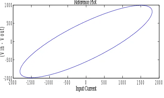
The transformer nature can be studied by considering it in healthy as well as faulty conditions [14]. A 1MVA, 33/11kV transformer winding was simulated in order to study its nature on the occurrence of certain fault as well in case of no fault condition. The healthy graph comes out to be as shown in Fig.2.
Fig. 2: Reference Plot
The transformer healthy condition plot in Fig.2 shows that its nature is elliptical. IEC [15] recommends the measurement of the leakage inductance while testing of transformers.
Now if a fault condition is taken into consideration, the fault condition being a shunt fault or most commonly known as leakage fault then the above graph turns out be something as shown in Fig.3.
TABLEIV
VISUAL METHODS OF DIAGNOSING TRANSFORMER FAILURES
Method Purpose
Inspecting Visually Detect leakage, contamination etc.
Thermography
Detect sources of heat
Thermal Monitoring Detect hot spots
Ultra-Violet Camera Detect Corona Discharge
-2000 -1500 -1000 -500 0 500 1000 1500 2000
-1000 -500 0 500 1000
Input Current
(V
in
V
o
u
t)
Fig.3: Shunt Fault
As can be seen in Fig.3 that the shunt fault leads to an increase in size of the plot and as compared to the healthy plot the shunt fault condition is extremely large as well as rotated.
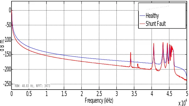
Another method of comparing all the faults is by determining its frequency response. In order to observe the frequency response of the implemented model in fault as well as in healthy conditions the model is simulated again in MATLAB/SIMULINK. The obtained frequency response is shown in Fig.4.
Fig. 4: Frequency Response Comparison of Shunt Fault and Healthy Condition
As can be seen in the Fig.4 the leakage fault does have a significant effect on the response in the range of lesser frequency where the plot is shifted in the downward direction for the lower frequencies whereas for the higher frequencies i.e. for frequencies above 30 kHz an observable rise in the magnitude is witnessed. At the frequency above 45 kHz the voltage magnitude suddenly decreases in comparison to the healthy condition.
-1.5 -1 -0.5 0 0.5 1 1.5
x 105 -2
-1 0 1
2x 10
4
Input Current
V
in
V
o
u
t
Shunt Fault
Healthy SHF
0 0.5 1 1.5 2 2.5 3 3.5 4 4.5 5 x 10⁴ -250
-200 -150 -100 -50 0
Frequency (kHz)
d
B
m
RBW: 48.83 Hz, NFFT: 3073
Voltage Measurement1 Healthy
V. CONCLUSION
A brief study has been carried out on the various tensions acting on the transformer and the effects of these tensions on the transformer condition. Also the various diagnostic techniques have been discussed briefly out of which the Frequency Sweep Method is considered to be most sensitive in case of mechanical deterioration while the Dissolved Gas Analysis as well as Furan Analysis prove to be beneficial in detecting the thermal faults.
The transformer has been modeled using two methods. The first method compares the healthy plot with the faulty plot with the help of the transformer winding model. In the second method the frequency response in case of the healthy as well as faulty transformer is shown. Considerable changes have been observed in both the cases. Thus both the methods have proven to be effective in terms of identification of fault in the transformer. Therefore we can conclude that in a way these methods demonstrate to be a preventive technique where the transformer fault is considered.
REFERENCES
[1] CIGRE Working Group 12-05, “An international survey on failures in large power transformers in service,”Electra-088, May 1983.
[2] M Wang, A.J. Vandermaar,K.D. Srivastava, “Review of condition assessment of power transformers in service, IEEE Electrical Insulation
Magazine,vol 18,no. 6,Nov-Dec 2002.
[3] CEA Report, “Failure of 220 k.V. and above voltage class substation equipment,” under Ministry of Power, Government of India, March 2016.
[4] M.S.A. Minhas, J.P. Reynards, P. J. De Klerk, “Failures in power system transformers and appropriate monitoring techniques,”Proceedings of
Eleventh High Voltage Engineering Symposium, 1999, Conference Publication No.467, 22-27 August 1999, pp. 94-97.
[5] V. Sokolov, Z. Berler, V. Rashkes, “Effective methods of assessment of insulation system conditions in power transformers: A view based on
the practical experience,” Proceedings from Electrical Insulation Conference and Electrical Manufacturing & Coil Winding Conference,
October 1999, pp. 659-667.
[6] K.Siderakis,D. Pylarinos,E. Thalassinakis, “Power transformers management in the power system of Crete,”Proceedings of the 9th
International Conference on Deregulated Electricity Market Issues in South Eastern Europe, Nicosia,Cyprus,25-26 September,2014.
[7] J Singh, Y. R. Sood, P. Verma, R. K. Jarial, “Novel method for detection of transformer winding faults using Sweep Frequency Response
Analysis,” IEEE Power Engineering Society General Meeting,24-28 June 2007, pp. 1-9.
[8] R Rahimpour, J. Christian, K. Feser, H. Mohseni, “Ability of transfer function method to diagnose axial displacement of transformer windings,”
European Transactions on Electrical Power, vol. 12, no. 3, May/June 2002.
[9] IEEE Standard C57.104, “IEEE Guide for the interpretation of gases generated in oil-immersed transformers,”2008.
[10] A. Abu-Siada, S. Islam , “A new approach to identify power transformer criticality and asset management decision based on dissolved
gas-in-oil analysis,” IEEE Transactions on Dielectrics and Electrical Insulation, vol. 19,issue 3,June 2012.
[11] L. E. Lundgaard, W. Hansen, D. Linhjell and T. J. Painter, "Aging of oil-impregnated paper in power transformers," in IEEE Transactions on
Power Delivery, vol. 19, no. 1, pp. 230-239, Jan. 2004.
[12] T. K. Saha, "Review of modern diagnostic techniques for assessing insulation condition in aged transformers," in IEEE Transactions on
Dielectrics and Electrical Insulation, vol. 10, no. 5, pp. 903-917, Oct. 2003.
[13] B.Garcia, J. C. Burgos, A. Alonso, “Winding deformations detection in power transformers by tank vibrations monitoring,” Journal of Electric
Power Systems Research, vol. 74, no.1,pp. 129-138.
[14] M. Bigdeli, H. Firoozi, “Evaluation of novel monitoring methods in condition assessment of power transformers,” Journal of Advanced
Electrical and Computer Engineering, Nov. 2013, vol. 1, no.1, pp. 1-13.