ISSN(Online): 2319-8753 ISSN (Print): 2347-6710
I
nternational
J
ournal of
I
nnovative
R
esearch in
S
cience,
E
ngineering and
T
echnology
(A High Impact Factor & UGC Approved Journal)
Website: www.ijirset.com
Vol. 6, Issue 8, August 2017
Analysis and Simulation of Adaptive Power
System with Fuzzy Control for Managing
Dynamic Loads
Daruvuri Sumasree1, G.B.Sankara Rao2
P.G. Student, Department of EEE, R.V.R. & J.C. College of Engineering (Autonomous), Guntur ,
Andhra Pradesh, India1
Associate Professor, Department of EEE, R.V.R. & J.C. College of Engineering (Autonomous), Guntur,
Andhra Pradesh, India2
ABSTRACT: This paper proposes an Adaptive Power System with fuzzy logic controller, it is used to mitigate the negative impacts present on the ship platforms resulting from large dynamic loads. The Navy’s future and near-term high-energy sensors and energy weapons will consume a large portion of the resources of the intended ship platform. These new systems will have extreme dynamic power profiles, including both periodic and a periodic characteristics. These dynamics can cause sudden changes in power at the prime power system that can be stressing to platform systems, both to the generators and prime movers. By using the fuzzy controller for a nonlinear system allows for a reduction of uncertain effects in the system control and improve the efficiency. The APS has used to maintain generator/prime-mover reliability, and also it is used to improve sensor/weapon performance or improve metrics such as system weight, cooling demands, and ship fueling costs. By using the simulation results we can analyze the proposed method.
KEYWORDS: AC/DC converter, DC/DC converter, Adaptive power system (APS), fuzzy logic controller (FLC), Dynamic load profile.
I. INTRODUCTION
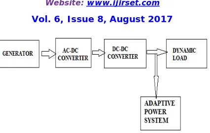
The Adaptive Power System (APS) concept presented in this paper can be an enabling technology for sensors or weapons with large dynamic loads. If the dynamic profiles propagate back to the ship's electric plant, significant power-quality issues and generator/distribution losses can occur [1], [2]. In addition, the dynamic pulse loading may cause wear and tear on the gensets' mechanical parts [3]–[5]. The APS consists of energy storage, a bidirectional current source, and innovative control techniques. These innovative control techniques increase the energy storage utilization, thus minimizing the energy storage size. A block diagram of a conventional shipboard power system is shown in the Figure 1. Conventional systems have focused heavily on providing well-regulated voltages and clean power to the corresponding load. If the voltage dynamics seen at the load are to be minimized, the output impedance of each converter stage is minimized by using small series inductance values, large shunt capacitance values, and control loops with high bandwidths.
ISSN(Online): 2319-8753 ISSN (Print): 2347-6710
I
nternational
J
ournal of
I
nnovative
R
esearch in
S
cience,
E
ngineering and
T
echnology
(A High Impact Factor & UGC Approved Journal)
Website: www.ijirset.com
Vol. 6, Issue 8, August 2017
Fig. 1. A block diagram of a notional power system with the APS attached
The time limit for the enhanced operation is limited by the APS size, the size of the energy storage needed to provide the delta power, and the maximum average power allowed. This maximum allowed average power determines the corresponding duty cycle of this enhanced operation and hence the quickest allowed recharge time of the APS energy storage.
Consequently, a new approach is needed to manage the load dynamics of emerging Navy systems, The Adaptive Power System (APS) specifically addresses this need. The APS can be used to efficiently mitigate bus disturbances and reduce stress to the shipboard gensets by converting the dynamic power load seen by the shipboard power system into an equivalent rolling time average – essentially serving as an active low pass filter to the load dynamics. As shown in Figure 1, the APS can be added to an existing system. The APS consists of energy storage, a passive power filter, a bi-directional current source, and innovative control loops, as shown in Figure 2.
The bi-directional current source efficiently delivers the pulsed power demand from the APS energy storage to the desired sensor or weapon system, thus providing a buffer to the upstream power equipment.
The APS is similar to the active filter concept whereby the active filter provides the current needed to maintain the quality of the load current required by the upstream power system. Active filters have been used for years in alternating current (AC) power systems to reduce the current harmonics and improve the power factor presented to the source when the loads are nonlinear and electrically noisy [6]–[8].
In addition, active filters have recently become popular in direct current (dc) systems to reduce conducted emissions caused by the pulse-width modulation (PWM) switching action of the dc/dc converter load [9]. With the proper use of control loops and energy storage, the APS can reduce the rate at which the power demand on the generator changes, thus limiting the dynamics and spectral content seen by the generator - transforming a weapon or sensor system that had otherwise been incompatible with the platform’s power system into one that is now feasible.
II. ADAPTIVE POWER S YSTEM (APS)
A.Overview
ISSN(Online): 2319-8753 ISSN (Print): 2347-6710
I
nternational
J
ournal of
I
nnovative
R
esearch in
S
cience,
E
ngineering and
T
echnology
(A High Impact Factor & UGC Approved Journal)
Website: www.ijirset.com
Vol. 6, Issue 8, August 2017
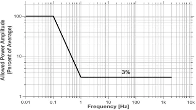
Fig. 3. The power ripple filtering requirement of the APS
The APS implementation must also not interfere with maintaining a stiff voltage (tightly regulated voltage) to the load. The top-level components of the APS include the energy storage capacitance and two control loops. One loop controls the APS output current to provide the required dynamic current to the load using the energy from the storage capacitance, and the other loop maintains the voltage across the energy storage capacitance to within the allowed rating. Figure 2 provides the detail voltage and current waveforms for the APS as well as the generator power waveform during the application of a dynamic load profile.
Operation of the Adaptive Power System is as follows:
• The current provided from the upstream power system is regulated by the APS to be equal to the filtered (0.13 Hz) current profile of the load demand. The compensation block regulates Ibus to be equal to Iref by controlling the output current of the bi-directional current source (BDCS); see the bus-current and BDCS-current waveforms in Figure 2. The BDCS is a DC/DC converter that can process power in both directions – it can both absorb and deliver power.
• Hence, the AC component or dynamics of the load profile is not part of Ibus but is provided by the energy-storage capacitance via the BDCS.
• The energy-storage capacitance value is selected to be large enough to provide the source and sink currents to support the pulsed load demand. The value for the energy-storage capacitance is minimized by allowing the voltage across Cstore to vary significantly, where Udelivered = 1/2 Cstore(Vt20 − Vt2+), minimizing the energy storage capacitance
required.
ISSN(Online): 2319-8753 ISSN (Print): 2347-6710
I
nternational
J
ournal of
I
nnovative
R
esearch in
S
cience,
E
ngineering and
T
echnology
(A High Impact Factor & UGC Approved Journal)
Website: www.ijirset.com
Vol. 6, Issue 8, August 2017
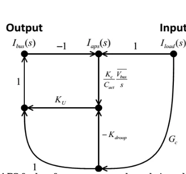
Fig. 4. Signal flow graph of APS for low frequency energy loop design where Ibus = Iref and Iload = Iload.
• The voltage variation across Cstore is also decoupled from the load, allowing tight regulation of the bus voltage seen by the load to be maintained. Udelivered is the energy delivered or absorbed by the storage capacitance, and Vt0 and Vt+ are the corresponding voltages across the energy-storage capacitance just prior to the load disturbance and after the energy-storage capacitance has delivered or absorbed the desired energy
B.APS Requirements for Notional System
To demonstrate the APS functionality and performance, a top-level design and simulation for a notional 300-kW system was performed. For this specific system the APS interfaces with the 375-VDC bus, as shown in Figure 1. The system was designed to support the following load and input–output performance specifications:
• Duty Cycle of Load: 0 to continuous • Average Load Power: 0 to 300 kW • Peak Load Power: 0 to 300 kW
• Input Voltage: 4160 VAC per MIL-STD-1399-680 • Input Interface Power Ripple Requirements: Figure 3
• Voltage Transients at the 375-V Bus Load Interface: maintain to better than ±5%
C.APS Design Details for Notional System Control Loop Bandwidth Considerations:
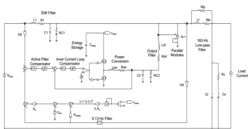
Figure 5 provides the schematic details for the APS. The bi-directional current source is a modular design consisting of thirty-eight 8-kW modules.
ISSN(Online): 2319-8753 ISSN (Print): 2347-6710
I
nternational
J
ournal of
I
nnovative
R
esearch in
S
cience,
E
ngineering and
T
echnology
(A High Impact Factor & UGC Approved Journal)
Website: www.ijirset.com
Vol. 6, Issue 8, August 2017
Fig. 5. The high-level schematic of an APS system used for simulation, where N is the total number of parallel modules (N=)38
To simplify the analysis, the preceding assumptions have been used, and therefore this signal flow graph is only valid for low frequencies. In Figure 4, Ibus is the controlled upstream bus current coming from the 375-V converter, Iload is the current to the load before the 160-Hz filter, and Gc is the transfer function of the 0.13-Hz filter, which has been selected to be a second order filter defined as
=
( ( ) ) (1)
where ω c is the corner frequency (in rad/s) and ζ is the damping ratio. In this example, ζ is equal to 0.9.
In addition, Ku is the energy-loop gain that determines the energy outer loop bandwidth, Kdroop is the gain of the energy droop compensation (in J/A), Cact is the actual capacitance of Cstore (in Farads), and Kc is the capacitance value (in Farads) used in converting the measured capacitor bank voltage, Vstore, to energy, the transfer function
can be determined as follows:
( )
( )=∑
∆
∆ (2)
where N is the total number of forward paths, Pk is the gain of the kth forward path, Δ is the determinant, and Δk is
the cofactor of path k. The gain of forward paths are defined as
= , (3) =− , (4)
= , (5)
where the bar over Vbus indicates a constant average value. There is only one loop in Figure 4, which is defined as
ISSN(Online): 2319-8753 ISSN (Print): 2347-6710
I
nternational
J
ournal of
I
nnovative
R
esearch in
S
cience,
E
ngineering and
T
echnology
(A High Impact Factor & UGC Approved Journal)
Website: www.ijirset.com
Vol. 6, Issue 8, August 2017
TABLE I
SIZE ANDWEIGHT OF THEAPS SYSTEM
The determinant is then
∆= 1− = 1 + (7)
Because the loop, L, touches all the forward paths, the cofactor for each forward path is simplify defined by
∆ =∆ =∆ = 1 (8)
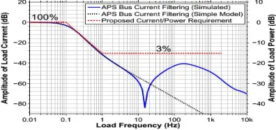
Fig. 6. The bus current filtering performance of the APS with the proposed requirement overlaid (for example, a 100 kW average load is allowed 3 kW peak ripple at 1 Hz). Because the bus voltage is approximately constant, current filtering directly relates to power filtering.
Figure 6 demonstrates that this equation’s predictions (black dashed line) are nearly identical to the detailed simulation results (solid blue line) up to 4 Hz, at which point interactions with the current control-loop compensator begins to appear. Figure 6 provides the time-constant requirement via the frequency-domain specification needed to determine the storage-capacitance nominal value, Cdesign.
This results since K droop’s units are Joules/Ampere. Knowing the amount of energy used,
= (9)
= ( − ) (10)
along with the maximum available energy for use the corresponding capacitance value can be solved for
= (11)
ISSN(Online): 2319-8753 ISSN (Print): 2347-6710
I
nternational
J
ournal of
I
nnovative
R
esearch in
S
cience,
E
ngineering and
T
echnology
(A High Impact Factor & UGC Approved Journal)
Website: www.ijirset.com
Vol. 6, Issue 8, August 2017
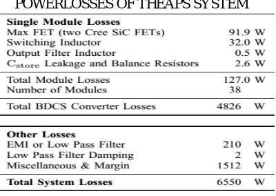
Table II provides a summary of predicted component losses. The MOSFETs used in the implementation of the BDCS are silicon carbide devices. Silicon carbide devices are selected because of the inherently low drain to source parasitic capacitance, which is crucial to minimizing the switching losses when operating at the high voltage levels with hard switching.
TABLE II
POWERLOSSES OF THEAPS SYSTEM
III. PROPOSED REQUIREMENTS
The Navy’s MIL-STD-1399-680 addresses pulse loading requirements, but only deals with pulses that occur infrequently – less than once every 45 seconds [11]. A requirement is needed that protects the genset and distribution bus against the dynamics resulting from frequent and repetitive pulsing loads but which is not as restrictive as the present requirement of only allowing a single pulse once every 45 seconds. Meeting the following requirement would provide this protection, and with the use of the APS, this requirement is feasible to implement, even for systems with large dynamic power profiles.
Proposed Pulsed Load Requirement:
The combined three-phase peak power ripple as seen by the shipboard generator(s) at any single frequency generated by the load shall be less than the limits defined by Figure 3. The resulting allowed load profile proposed in Figure 3 has been matched to the generator and prime mover performance. Typical gensets’ response times to a significant load change are on the order of 1.0 to 1.5 sec [12], [13]. If the rise and fall times for power changes (ramp rate) seen by the generator are controlled to be slower than the genset’s response times, the generator and prime-mover control loops will be able to maintain the voltage and speed regulation, bus disturbances will be kept to a minimum for such a slow-changing power profile, and sub-synchronous resonances will not be excited because the disturbances are at lower frequencies.
FUZZY LOGIC CONTROLLER
ISSN(Online): 2319-8753 ISSN (Print): 2347-6710
I
nternational
J
ournal of
I
nnovative
R
esearch in
S
cience,
E
ngineering and
T
echnology
(A High Impact Factor & UGC Approved Journal)
Website: www.ijirset.com
Vol. 6, Issue 8, August 2017
Fig.7.Fuzzy logic controller
The FLC comprises of three parts: fuzzification, interference engine and defuzzification. The FC is characterized as i. seven fuzzy sets for each input and output. ii. Triangular membership functions for simplicity. iii. Fuzzification using continuous universe of discourse. iv. Implication using Mamdani’s, ‘min’ operator. v. Defuzzification using the height method.
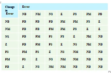
TABLE III: Fuzzy Rules
Fuzzification:
Membership function values are assigned to the linguistic variables, using seven fuzzy subsets: NB (Negative Big), NM (Negative Medium), NS (Negative Small), ZE (Zero), PS (Positive Small), PM (Positive Medium), and PB (Positive Big). The Partition of fuzzy subsets and the shape of membership CE(k) E(k) function adapt the shape up to appropriate system. The value of input error and change in error are normalized by an input scaling factor.In this system the input scaling factor has been designed such that input values are between -1 and +1. The triangular shape of the membership function of this arrangement presumes that for any particular E(k) input there is only one dominant fuzzy subset. The input error for the FLC is given as
E(k) = ( ) ( )
( ) ( ) (12)
CE(k) = E(k) – E(k-1) (13)
Inference Method:
ISSN(Online): 2319-8753 ISSN (Print): 2347-6710
I
nternational
J
ournal of
I
nnovative
R
esearch in
S
cience,
E
ngineering and
T
echnology
(A High Impact Factor & UGC Approved Journal)
Website: www.ijirset.com
Vol. 6, Issue 8, August 2017
Defuzzification:
As a plant usually requires a non-fuzzy value of control, a defuzzification stage is needed. To compute the output of the FLC, „height‟ method is used and the FLC output modifies the control output. Further, the output of FLC
controls the switch in the inverter. In UPQC, the active power, reactive power, terminal voltage of the line and capacitor voltage are required to be maintained. In order to control these parameters, they are sensed and compared with the reference values. To achieve this, the membership functions of FC are: error, change in error and output The set of FC rules are derived from
u=-[α E + (1-α)*C] (14)
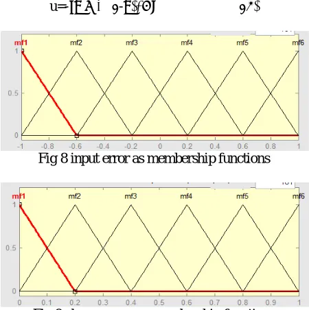
Fig 8 input error as membership functions
Fig 9 change as error membership functions
Fig.10 output variable Membership functions
ISSN(Online): 2319-8753 ISSN (Print): 2347-6710
I
nternational
J
ournal of
I
nnovative
R
esearch in
S
cience,
E
ngineering and
T
echnology
(A High Impact Factor & UGC Approved Journal)
Website: www.ijirset.com
Vol. 6, Issue 8, August 2017
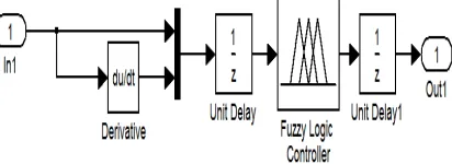
Fig11. Block diagram of simulation
Fig 12. Control block diagram of simulation
Fig13. Block diagram of fuzzy logic controller
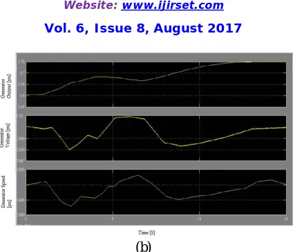
B.Simulation results for Notional System
To demonstrate the effectiveness and benefits of the APS, Figures 14(a) and 14(b) provide simulation results for various waveforms in the system when a dynamic load is applied both with and without use of the APS.
ISSN(Online): 2319-8753 ISSN (Print): 2347-6710
I
nternational
J
ournal of
I
nnovative
R
esearch in
S
cience,
E
ngineering and
T
echnology
(A High Impact Factor & UGC Approved Journal)
Website: www.ijirset.com
Vol. 6, Issue 8, August 2017
ISSN(Online): 2319-8753 ISSN (Print): 2347-6710
I
nternational
J
ournal of
I
nnovative
R
esearch in
S
cience,
E
ngineering and
T
echnology
(A High Impact Factor & UGC Approved Journal)
Website: www.ijirset.com
Vol. 6, Issue 8, August 2017
(b)
Fig. 14. Simulation results of the first load profile at Load and Generator. (a) Without APS. (b) With APS.
Fig. 14(a) The results also demonstrate that the ac/dc and dc/dc converters do little to reduce the low to medium frequency content, with most of the dynamic load appearing at the generator terminals when the APS is not used. Fig. 14(b) also shows the voltage waveform of the storage capacitor and the current waveform of the bi-directional current source, demonstrating the APS’s capability of providing the dynamic demand of the load resulting in the generator only having to provide the rolling average of the load power profile.
The 375-V bus voltage delivered to the load is also shown in Fig. 14(b), indicating that the 5% transient regulation requirement is met. At time 6.5 s in Fig. 7(b), the load switches to a constant load and the APS consumes no power (APS output current goes to zero) after about 5 s from this point in time, demonstrating the efficient conditioning method provided by the APS.
IV. CONCLUSION
In this paper the Adaptive Power System (APS) with fuzzy logic controller concept presented can be an enabling technology for sensors or weapons with large dynamic loads, which without the APS would be incompatible with the upstream shipboard generator and distribution bus. In FLC, basic control action is determined by a set of linguistic rules. These rules are determined by the system. The APS consists of energy storage, a bidirectional current source, and innovative control techniques. The APS has used to maintain generator/prime-mover reliability, and also it is used to improve sensor/weapon performance or improve metrics such as system weight, cooling demands, and ship fueling costs. By using the fuzzy controller for a nonlinear system allows for a reduction of uncertain effects in the system control and improve the efficiency. The APS design with fuzzy controller is presented along with simulation results verifying the concept. By using the simulation results we can analyze the proposed method.
REFERENCES
[1] F. Kanellos, I. Hatzilau, and J. Prousalidis, “Investigation of voltage/frequency modulation in ship electric networks with pulsed loads according to stanag 1008 design constraints,” in All Electric Ship Conference, 2007.
[2] IEEE Recommended Practices and Requirements for Harmonic Control in Electrical Power Systems, IEEE Industry Applications Society/Power Engineering Society Std. 519-1992, 1993.
[3] M. Baldwin, “Electric arc furnace impact on generator torque,” in Power Systems Conference and Exposition, 2004. IEEE PES, 2004, pp. 776– 780 vol.2.
[4] G. J. Tsekouras, F. D. Kanellos, J. M. Prousalidis, and I. K. Hatzilau, “Stanag 1008 design constraints for pulsed loads in the frame of the all electric ship concept,” Nausivios Chora, vol. 3, pp. 113–152, 2010. [Online]. Available: http://nausivios.snd.edu.gr/nausivios/docs/b3 2010. pdf [5] H. Smolleck, S. Ranade, N. R. Prasad, and R. Velasco, “Effects of pulsed-power loads upon an electric power grid,” Power Delivery, IEEE Transactions on, vol. 6, no. 4, pp. 1629–1640, Oct 1991.
[6] B. Singh, K. Al-Haddad, and A. Chandra, “A review of active filters for power quality improvement,” Industrial Electronics, IEEE Transactions on, vol. 46, no. 5, pp. 960–971, Oct 1999.
ISSN(Online): 2319-8753 ISSN (Print): 2347-6710
I
nternational
J
ournal of
I
nnovative
R
esearch in
S
cience,
E
ngineering and
T
echnology
(A High Impact Factor & UGC Approved Journal)
Website: www.ijirset.com
Vol. 6, Issue 8, August 2017
[9] D. Hamza and P. Jain, “Conducted emi noise mitigation in dc-dc converters using active filtering method,” in Proc. IEEE Power Electron. Specialists Conf., Jun. 2008, pp. 188–194.
[10] N. Mohan, Power Electronics: A First Course. Hoboken, NJ, USA:Wiley, 2012.
[11] High Voltage Electric Power, Alternating Current, Department of the Navy Standard MIL-STD-1399-680, 2008.