Multi-Body Dynamic Analysis Computer Program
For the Prismatic Core of a HTGR
Ji-Ho Kang
Senior Researcher, Korea Atomic Energy Research Institute, Korea
ABSTRACT
A computer program has been developed for the prismatic core of a HTGR (High Temperature Gas-Cooled Reactor). The program was not completed yet; however, the modulized feature of the program makes it possible to test the completed modules for the lateral and vertical forces. Example problems were defined to verify the developed computer program by comparing with theoretical and a commercial code results. The developed computer program showed very good agreements in the comparison. In the near future, the program will be completed and the seismic response of the HTGR core will be simulated.
INTRODUCTION
The prismatic core of a HTGR consists of an array of hexagonal graphite blocks as shown in Figure 1. In Korean prismatic HTGR designs, the graphite blocks are stacked inside of the core barrel without mechanical joints. The upper and lower blocks in a column are connected with the dowel pin/socket structures for the vertical alignment. However, the dowel joints do not constrain the vertical and rotational motions of blocks. Also, there are small gaps between adjacent block columns for the replacement of the blocks and the gap sizes are known to increase for the lifetime of the blocks by the neutron-induced volumetric contraction of graphite materials. From these unique characteristics of the prismatic core, the blocks will show horizontal movements and rocking motions. These relative motions of blocks are summed up and can make a considerable collision with adjacent blocks. Therefore, it is required to analyse the behaviour of the prismatic core and evaluate the structural integrity of the individual blocks. The purpose of this study is to develop a computer program that simulates the dynamic response of the prismatic core which is modelled as a 2-D vertical cross-section of the core and estimate the structural integrities of graphite blocks. As the beginning stage of the study, the governing equations of the block motion will be proposed and the solving algorithm will be introduced. The program is not complete yet; however, some module level verification examples were simulated and the results were verified by theoretical results and code-to-code benchmarks.
GOVERNING EQUATIONS OF MOTION
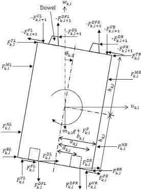
The original forms governing equations of motions were introduced in the paper of Iyouku et al. (1992). Generally, the maximum impact force by the collision between two columns of blocks or between a column of blocks and the core boundary occurs at the vertical 2-D cross-section on which the center of the core lies, where the largest number of blocks participate in the horizontal movement. In Figure 2. three columns of blocks inclines to the right at a specific moment and then the maximum impact load occurs at the side boundary because number of columns that participate in the collision is the largest. In this concept, the maximum impact load is assumed to occur on the vertical 2-D cross-section passing on the center of the core. With this assumption, an individual block is modelled as a 2-D rigid body rectangular box with two dowel pins on the upper line of the box and two dowel sockets on the lower line of the box. Figure 3 shows the 2-D model of an individual block and all the forces that can be applied on the block from the surrounding objects.
Figure 2. Collision of the columns of blocks by a seismic motion.
Figure 3. 2-D dynamic model of a graphite block.
!",#$%",#=&"'(,# +&")(,# +&"*(,# +&"+(,# +&"',,# +&"),,# +&"*,,# +&"+,,# +&"&(,# +&"&,,# - &"&(,#+1- &"&,,#+1+&".(,# +&".,,# - &".(,#+1- &".,,#+1
(1) !",#/%",# =&"0(,# +&"0,,# - &"0(,#+1- &"0,,#+1+&".&(,# +&".&,,# - &".&(,#+1- &".&,,#+1- !",#1 - &"2,#
(2) 3",#4%",# =)",#'(+)",#)(+)",#*(+)",#+(+)",#',+)",#),+)",#*,+)",#+,+)",#&(+)",#&,+)",#+1&( +)",#+1&, +)",#.(
+)".,,# +)".(,#+1+)".,,#+1+)"0(,# +)"0,,# +)"0(,#+1+)"0,,#+1+)".&(,# +)".&,,# +)".&(,#+1
+)".&,,#+1+)"5,#+)"2,#
(3)
where, the subscript, (k,l), is the column and row index of the block in the core array and Mis moment
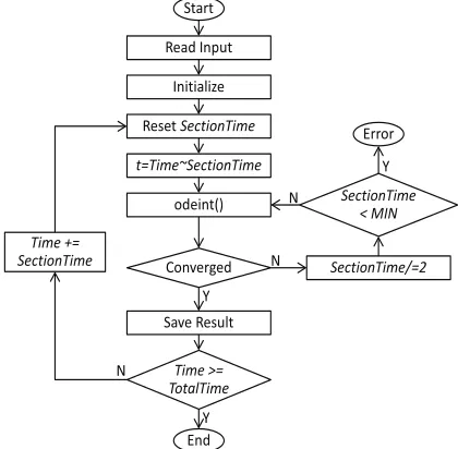
around the block center of mass. There were noticeable improvement in the force layout and the governing equations from those of Iyoku (1992). (Detail explanation was not possible by the limitation of the pages.) These three ordinary differential equations can be solved in various ways. In this study, the Runge-Kutta method or the ODEPACK library (a collection of Fortran solvers for the initial value problem for ordinary equation systems) can be selected by the choice of user. Figure 4 shows the brief flowchart of the program.
The main numerical issues were on the calculation of the force and moment terms in equations (1)~(3) properly and correctly. The most of force and moment terms in the equations are independent to each other Therefore, the each force term is programmed as one module and the relevant moment is calculated in the module. There was an exception that the friction forces and friction-related moments should be calculated with the vertical reaction forces in a same module together. It is because the friction forces can be calculated only if the vertical reaction forces are known. Due to the modulization, the program can be tested whenever a new force module is added and also the user can select modules to be active in the calculation to provide the module-wise test. Currently, the modules for the lateral and vertical forces, dowel forces, and friction forces were programmed and verified. Modules for remaining terms will be complete in the near future. The verification examples in this paper are related only to the lateral and vertical forces. Y N N Y Y N odeint() Read Input Initialize t=Time~SectionTime SectionTime/=2 Converged Reset SectionTime SectionTime < MIN Error Time >= TotalTime Save Result End Start Time += SectionTime
VERIFICATION WITH THEORETICAL SOLUTIONS
The developed program was verified with two theoretical solutions. The two examples were the free vibration of a block with initial velocity and the free-fall and restitution under the gravitational load. The theoretical solution of the first example is:
(4)
where, !is the damping ratio, "n is the natural frequency of the system. and "dis the frequency of the
damped oscillation. Figure 5 shows the numerical results of the developed program and the theoretical results. They showed a very good agreement.
Figure 5. Theoretical solution and the numerical results for a free vibration problem.
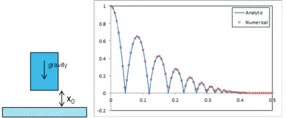
The theoretical solution of the second example can be expressed as:
, , ,
where,
(5)
Figure 6 shows the numerical results of the developed program and the theoretical results, and they also showed a very good agreement.
CODE-TO-CODE VERIFICATION
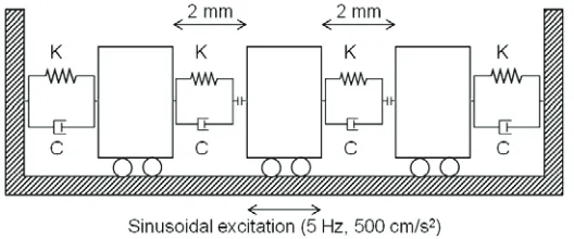
A code-to-code verification was performed on a more complex system. The calculation result was compared with a commercial FEM program, Abaqus v6.10 (2010). The system of interest is shown in Figure 7. In the system, one middle block is placed inside of a rigid vessel which is unconstrained at the beginning. There are two same blocks attached to the vessel side walls by a spring-damper connection which provides visco-elastic boundary for the middle block. When the unconstrained block collides to each side block, the same spring-damper connection works to simulate the block collision. In Figure 7, there is a gap component symbol attached to at one end of the spring-damper connection which provides switch-on of the spring-damper when the middle block contacts to the side blocks. The rigid vessel was
excited with sinusoidal acceleration of 5 Hz and 500 cm/s2. Figure 8 shows the lateral displacement of the
middle block and the two results are in good agreement.
Figure 7. Dynamic response problem of a block in a vessel with spring-restraints.
Figure 8. Numerical results of Abaqus and the developed program for the dynamic response of a block in a vessel with spring-restraints.
CONCLUSION
ACKNOWLEDGEMENTS
This work was supported by the National Research Foundation of Korea(NRF) grant funded by the Korea government (MSIP) (No.2012M2A8A2025679).
REFERENCES
Abaqus 6.10. (2010).User's Manual, Dassault Systèmes Simulia Corp., Providence.