Presentation of the criteria of the appendix 5.4 of the RSE-M code, devoted to the fracture mechanics parameters calculation
Stéphane Marie1, Patrick Le Delliou2, Stéphane Chapuliot1, Yann Kayser3, Philippe Gilles1
1
AREVA, 1 Place Jean Millier, 92400 Courbevoie, FR 2
EDF Les Renardières, 77818 Moret-sur-Loing, FR 3
CEA, DEN, DM2S, SEMT, LISN, 91191 Gif-sur-Yvette, FR
Abstract
Appendix 5.4 of the RSE-M code, devoted to in-service operation on PWR, provides all solutions and compendia required for the calculation of fracture mechanics parameters in nuclear components for relevant loading conditions. An important work of development has been made
since early 1990’s by AREVA, CEA and EDF and capitalised in this appendix 5.4.
To support the justification of these solutions and capitalise the related knowledge, AFCEN, in charge of the edition of the French nuclear codes, has launched the preparation of several criteria documents. This paper presents the criteria related to the appendix 5.4 and summarises their contain. A particular focus will be made on the stress intensity factor solutions, J parameter for mechanical loading, assessment of imposed displacement conditions, analysis of thermal chocks, weld mismatch impact and through-clad and under-clad defects in vessels. For each topic, historical elements, the development strategy and validation results will be presented.
1 Introduction
RSE-M code provides all rules for the PWR in-service operations [1]. In particular, appendixes 5.$ provide all methods and compendia to assess defects detected during inspections and to verify component’s integrity. The appendixes 5.$ are organised as follows:
· Defect geometry description – Appendix 5.1
· Defects interaction & defect acceptability tables – Appendix 5.2 · Fatigue & plastic instability - Appendix 5.3
o Fatigue crack initiation and propagation criteria
o Methods for crack initiation and crack propagation calculation (DKqq & DKcp) o Plastic instability criterion for a local reduction of the section thickness
· Fracture mechanics parameter calculation for defect stability assessment - Appendix 5.4
o KI and J solutions, Mechanical and thermal loadings considered
· Criterion for the defect stability assessment - Appendix 5.5
o Criterion definition in agreement with the French regulation requirements o With partial safety coefficients on the load and the material toughness
o Brittle and ductile failure for ferritic steel components – ductile failure for austenitic stainless steel components
· Material properties - Appendix 5.6
o Fatigue crack initiation and propagation laws (air and PWR environment), tensile
o Ferritic steels (Primary and Secondary components), austenitic stainless steels (forged
and cast), inconel alloy
Appendix 5.4 provides all methods and compendia for the calculation of Fracture Mechanics parameters KI and J, for nuclear components and related relevant loading conditions. The
solutions provided in this appendix are the result of more than 20 years of R&D work in France involving all main actors: AREVA, CEA, EDF and IRSN.
RSE-M subcommittee has decided to prepare a specific criteria document on the development of the appendix 5.4 to provide the technical bases of the RSE-M solutions, all explanations needed to understand the difference choices made during the development process and all elements on the validation process. The list of all public references will also be given. The criteria document structurefollows in the topics below:
· Stress intensity factor KI
· Kcp (small scale yielding condition – plastic zone correction) · J calculation under imposed mechanical load condition · Imposed displacement loading condition
· Thermal loadings · Welds
· Cladded components · List of references
This paper will provide an overview on some key elements of the different chapters of the criteria.
2 Impact of the French nuclear context on the development of the appendix 5.4 First of all, it is essential to underline the context of the development of these tools:
· The compendia, even if their final domain of definition is relatively wide, focus in priority on nuclear components (vessels and piping).
· The loading conditions are also relevant of nuclear needs: thermal chocks inducing high temperature through-thickness variation or imposed displacement loading condition for example.
· The analyses based on these tools do not allow any under-conservatism in the crack loading evaluation: the proposed method must be conservative on their entire domain of definition. This requirement lead to a specific strategy of development and validation, compare to the usual practice used for the development of best-fit solution.
· The key phases of the development of the solutions were presented and discussed with the French Nuclear Safety Authority (ASN). Even if there is no endorsement of the methodology by ASN, the exchanges allow to take into account their remarks and questions in the development process of the solution before the introduction into the code.
3 Stress intensity factor calculation
a t a i t a i t a i i
KI . . . .
3 3 3 2 2 2 1 1 0
0 s s s p
s ú ú û ù ê ê ë é ÷ ø ö ç è æ + ÷ ø ö ç è æ + + = 3 3 2 2 1
0 . . . ÷
ø ö ç è æ + ÷ ø ö ç è æ + + = ÷ ø ö ç è æ t u t u t u t u s s s s s
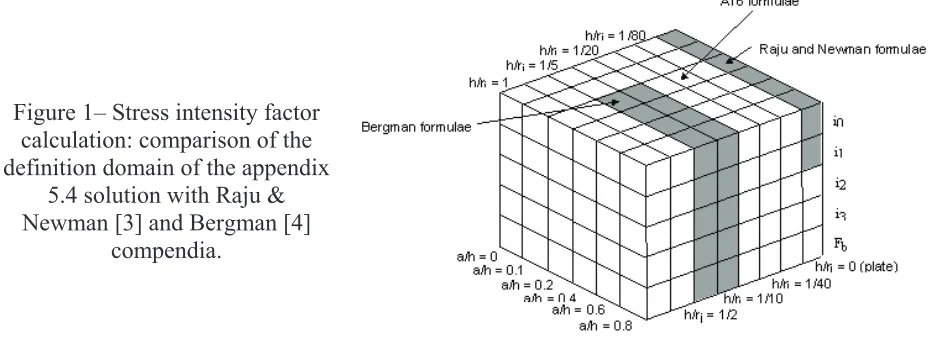
The compendia available in the appendix 5.4 have been developed specifically for AFCEN codes needs. A complete set of solution has been provided for cracked pipes and plates with through-wall and surface cracks, produced in 2000 [2]. The solution was compared in particular with available solutions at that time (Raju & Newman [3] and Bergman [4]). In figure 1, it can be seen that the scope covered by the compendia is very large in term of component and defect geometries. Still today, this solution is internationally acknowledged, as underlined in the recent work of Miura et al [5] who compared all main solutions available in the literature and concluded that for cracked pipes with a surface defect, the solution developed for AFCEN code is the recommended solution. A complementary work was performed to produce a compendium for internal defects in plates [6].
Figure 1– Stress intensity factor calculation: comparison of the definition domain of the appendix
5.4 solution with Raju & Newman [3] and Bergman [4]
compendia.
For cracked elbows, the number of relevant parameters for the characterisation of the geometry of an elbow with a surface crack is too high to develop a specific compendium of influence functions for the stress intensity factor calculation.
The appendix 5.4 proposes an alternative solution based on a classical observation that influence functions are little affected by the component geometry for shallow defect (a/t < 0.25). It is then proposed to use influence functions codified for cracked pipes with the same defect and a specific solution to estimate accurately the nominal elastic stresses everywhere in the elbow. This last solution was developed on the bases of 3D F.E. calculation of uncracked elbows for in-plane, out-of-plane and torsion moments [7]. Pressure solution is based on the classical toroidal assumption.
4 Kcp (small scale yielding condition – plastic zone correction)
For small scale yielding condition, a simplified solution to evaluate the crack loading has been proposed a long time ago, based on the classical plastic zone size concept. Nevertheless, the aim was to cover the first step of the plastic yielding around the crack tip. The proposed amplification is based on F.E. analyses on realistic stress-strain curve [9], with a criteria to define the limit of applicability insuring a constrained plasticity situation.
5 J calculation under imposed mechanical load condition
5.1 Theoretical bases
Historically, the first analytical solution for J calculation was proposed in the frame of an EPRI programme by Kumar and Shih [10]. Unfortunately, this solution being based on a power law tensile curve, it presents a reduced scope of validity and important difficulties of application, in particular for realistic tensile curves.
B. Ainsworth [11] brought the solution with the concept of the reference stress which provides an
‘universal’ formulation:
ú ú û ù ê
ê ë é
Y +
= 1
2 .
.
ref ref
I E
E K J
s e
Where the reference stress sref is a function of the imposed mechanical load and of the
component & defect geometries. The contribution of the mechanical behaviour is obtained through the reference strain eref, related to the reference stress on the tensile curve of the material,
whatever it shape. Y1 is a small scale yielding amplification for the first stages of the plasticity.
Appendix 5.4 solution is based on this formalism. If Ainsworth makes the link between the reference stress and the limit load of the crack component, it appears that the need of accurate predictions implies the development of specific limit load solutions. It was the path followed by the RSE-M developers.
5.2 Expert working group and associated R&D
The decision to develop an analytical fracture mechanics tool for Nuclear Power Plants has initially been taken in order to support the defect assessment for In-Service evaluations and for simple structures like piping systems where, when indications are discovered during ISI, fast and conservative evaluations are required. The analytical formula development for the ductile range started in the 90s, first by individual work in the different organisms involved in the nuclear field, but rapidly through cooperative work including the three major actors.
This working group is still active today and continues to develop and validate the tools for FMA. Some of the actual developments are focused on specific needs for EPR-UK, the RSE-M appendix 5.4 being the reference solution for fast-fracture analysis of class 1 components.
5.3 Scope
Since the beginning of the working group, a step by step approach was followed in order to cover a maximum of geometry and loading configurations encountered in nuclear pressure vessels and piping systems. Today, the formulae and methodologies presented in the appendix 5.4 are covering:
- Pipes and cylindrical shells containing circumferential or longitudinal, internal or external surface defects;
- Elbows with defects in mid or inlet/oulet sections, containing circumferential or longitudinal, internal or external surface defects;
- Tapered transitions with circumferential surface defects.
For all these structures, a large scope of loading types was investigated: mechanical loading, through thickness thermal loading (temperature gradient or thermal shock) or combined mechanical plus thermal loading (the two last cases are discussed in chapter 7). Again, the objective of this work is to cover a maximum of industrial configurations in support of defect assessment demonstrations. In every case, the process to develop new formulae is constituted by four major steps:
- First step is devoted to the constitution of a reference F.E. database;
- Second step is devoted to the methodology development of a new formula itself (reference stress for plastic corrections) with possibly complementary F.E. developments;
- Third step devoted to the final validation against the overall reference cases database;
- Fourth and final step devoted to pre-codification and presentation to the French Nuclear Safety Authority.
5.3 Reference F.E. database for the J parameter
The strategy adopted for the analytical schemes development and validation is based on the interpretation of reference F.E. results and then by a comparison between the analytical J and the same reference F.E. solutions. The constitution of reference F.E. modelling (through cracked elastic-plastic models) is thus a key point within that development scheme.
For that purpose, a F.E. results database was constituted in the frame of the cooperative CEA/EDF/AREVA R&D. F.E. models used for this database constitution are both 2D and 3D, depending on the problem treated. It was constituted step by step, starting from simple problems such as axi-symmetrical defects in pipes, up to complex cases like semi-elliptical defects in elbows.
At this step, it has to be mentioned that those F.E. modelling were in a major part performed by the experts involved within the working group, which guarantee a good confidence on the results.
the three partners using their own F.E. code: Code_Aster (EDF software – [13]), Cast3M (CEA software – [14]) and SYSTUS (AREVA software – [15] developed by ESI group).
This step, when accordance between the three different codes is required before the database building, constitutes the best validation process and allows the definition of best practice for meshes, loading applications, post-treatment… The model being validated, parametric models are then used in order to increase in a short time the number of F.E. results then complete the F.E. database.
All the numerical analyses are then reported in documents and the results included in the F.E. database in an imposed format in order to allow simple extractions of the results at the validation step. CEA is in charge of the maintenance of this database which contains today approximately 1000 different elastic-plastic solutions of cracked pipes, vessels and elbows, in both 2D and 3D configurations.
5.4 General formulation of the Js parameter
As mentioned, for mechanical loading, the Js formulation relies on the approach proposed by Ainsworth [11]. Some considerations were added in order to take into account influencing
parameters such as triaxiality, interaction between mechanical loadings, stress redistribution…
Within that frame, the correction due to plasticity for mechanical loading relies on a Lr parameter which allows the evaluation of the level of plasticity within the section containing the crack via the stress-strain curve of the material. The general formulation is the following:
ú û ù ê
ë é
y + s
e × ×
= RSEM
ref ref m
el
m J E
J with
2 2
RSEM
Lr 1
Lr . 2 1
+ = y
This formulation corresponds to a correction of a J determined through KI Stress Intensity Factor
(Jel = KI²/E) by a correction which depends on the ratio between the reference strain εref (strain
associated to reference stress σref = Lr.sy on the true stress-true strain tensile curve of the
material) and the elastic strain σref/E.
Except for the Y correction corresponding to a confined plasticity correction (limited to 0.5 in practice), this formulation is fully consistent with the R6 option 2 for treatment of primary stresses. At this step, the main difference between the two codes is on the supply of Lr (or sref)
solutions which is extensively developed for piping systems and vessels in appendix 5.4 whether R6 rules provide much less solutions: in a general case, the user has to provide his own formulae.
In appendix 5.4, two options (CLC and CEP options) are available to calculate the reference stress for the mechanical loading. Both of them rely on the same reference stress approach but with a slightly different formulation, the CLC one being strictly equivalent to the R6 formulation. The criteria document will detail the origin and the specificities of these two options.
5.5 Methodology for reference stress formulae development
The reference stress formulae were developed in the same manner through the post-analysis of F.E. modelling for the same panel of structures and defect shapes. The proposed reference stress formulas are then functions of the imposed load and the crack shape.
- Analysis of the individual loadings and development of the related solution; - Determination of the interactions between mechanical loadings.
At each phase, the initial solution is based on limit load solution, which is then adapted for the J calculation.
At this step, one should note that in order to avoid any error compensation, the elastic J coming from the F.E. model is used in the determination of plastic corrections, to be sure that all the differences obtained during the second step are only due to the reference stress proposed solutions.
5.6 Validation
When a new compendium of J is finalized (either global and defect specific formulae), a comparison of the analytical approaches to the F.E. reference database is performed. This confrontation is reported in validation documents giving, for each case in the reference database, the detail of differences between the analytical and reference approaches. Those reports are communicated and presented to the French regulator through specific meetings following the introduction of the developments within the code (in 1998 for pipe solutions, in 2002 and 2006 for elbows, and at last in 2010 for weld joint consideration).
The comparison between analytical scheme and the F.E. reference solutions is performed systematically, for all cases available within the database. The validation criteria have been defined taking into account the exchanges with the French safety authority: the goal is to develop a systematic conservative solution and not a best fit one: a positive bias is automatically introduced in the compendia. The difficulties of the development work were to meet this requirement and to keep a usable method with a limited positive bias.
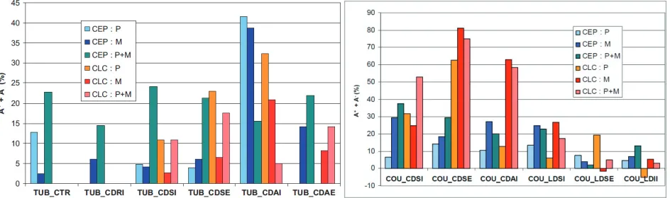
An example of such synthesis is presented on figure 2 for pipes (TUB) and elbows (COU). This graph represents for all defect positions and loading type, the mean global error on J obtained by application of the analytical scheme. It thus illustrates the bias between the analytical scheme and the F.E. modelling. For pipes, the average bias is around 10-20%. For elbows, which is a more complex case due to the important number of geometrical parameters involved, the average bias is around 40%. It is important to keep in mind that for nuclear material, with a strain hardening exponent around 5-6, each 10% on J corresponds in fact to less than 2% on the load.
Figure 2: Example of synthesis graph for pipes and elbows submitted to mechanical loading.
The 2015 addendum of the RSE-M code will include the already existing solution of the appendix A16 of the RCC-MRx code [12] for the imposed displacement loading condition. The principle of this solution is to come back to an imposed load situation taking into account:
· the contribution of the crack section and of the rest of the component, · the effect of plasticity on each contribution.
For a given imposed displacement or rotation, a large defect may lead to an important contribution, inducing a relaxation of the related mechanical load, compared to the case of a small defect or the case of the un-cracked component. The method catches this effect and allows an accurate prediction of the J parameter for imposed displacement situation or thermal stratification problem.
7 Thermal loading
The treatment of thermal loads has been particularly well investigated by the expert group and the solutions proposed by the appendix 5.4 are very efficient for the assessment of cracked components under thermal shock.
The developments were focused on through thickness temperature gradients. The overall temperature gradients such as stratification or global thermal expansion are not treated within that frame but with another specific approach devoted to ‘imposed displacement’ loading condition.
For such through thickness gradients (the industrial need regarding thermal shock evaluations) many numerical simulations were done and have shown the possible attenuation of J parameter due to plasticity. This phenomenon, linked to the attenuation of stresses under imposed strains for elastic-plastic material behaviour, is explained in [16] and can be summarized as follows:
· Thermal transient, and in particular through thickness thermal gradient, corresponds to an imposed strain. In that case, elastically determined stresses overestimate the real stresses which are reduced by plasticity. Elastic J must be reduced in order to take into account this effect of plasticity on stresses.
· On the contrary, plasticity in the cracked section and potential elastic follow-up between cracked and un-cracked sections can amplify the elastic J, as it is the case for mechanical loading.
To provide a reasonable approximation of those two opposite phenomena, a kth coefficient
multiplying those two corrections and eventually an interaction with mechanical loading (through the kth* coefficient) was defined. Generally, the coefficient kth is equal or smaller than 1 since the
stress reduction correction is dominating. The J parameter for an elastic-plastic behaviour is thus lower than the same parameter determined with an elastic model.
Regarding the interaction with mechanical loading, it has been shown that the most appropriate general formulation for combined thermal and mechanical loading is the following:
[
]
2* th
el th m th
m
J k J
J + = + × ,
where Jm is the contribution due to mechanical loading and Jelth the contribution due to thermal
The interaction between mechanical and thermal loading taken into account here is called ‘weak interaction’ since the plasticity amplification applied to the mechanical term (within Jm parameter through Lr or sref) is not applied to the thermal term Jelth. This constitutes a major difference with
the R6 rule (option 2) in which the plastic correction is imposed to both mechanical and thermal contributions. This solution is not able to represents the crack loading relaxation induced by plasticity: consequently, the elastic-plastic J evaluated through the R6 analytical scheme is systematically higher than the elastic one, and thus over conservative in comparison to the F.E. reference results showing the inverse trends for thermal shocks loading conditions.
Another important work performed for thermal loading focuses on the development of analytical solution to evaluation the through thickness temperature and related stresses distribution in the case of a thermal transient. The developments lead to analytical solution able to take into account with a limited number of assumptions on the physical properties of the materials:
· a complex fluid temperature variation (even cyclic) [17], · the influence of an internal cladding [17],
· the variation of the heat exchange coefficient between the fluid and the internal surface of the component [18].
8 Cracks in welds
A J-estimation scheme for cracks in welds was developed, to take benefit of the mismatch between the tensile properties of the weld material and those of the base material. This estimation scheme is based on the same approach as the R6 guide and uses an ‘equivalent’ stress-strain curve interpolated from the base material and the weld stress-strain curves. This approach was first developed by Lei and Ainsworth [19] for a CCT specimen. It consists in calculating an equivalent stress-strain curve from the base material and the weld stress-strain curves, using ratio between the limit load of the all-base material structure FLb and the limit load of the mismatched
structure FLmis.
However, considering first that the determination of the mismatch limit load is a difficult task, and secondly that the limit load ratio FLmis/FLb is not necessarily the parameter giving the best
J-estimate, a slightly different definition was used for the ‘equivalent’ stress-plastic strain curve:
( )
(
( )
)
( )
(
( )
)
( )
1 1
-+
-=
M
M M
M w p b p
p e
e s a e
s a
e s
where M is the mismatch ratio and a(M) is a function which has been tabulated: For the appendix 5.4, explicit expressions of the weighing function called a(M) are given for axi-symmetrical or semi-elliptical cracks in a straight pipe loaded in axial tension or in bending [21]. These expressions take into account the geometry of the weld joint (width of the root and slope of the groove). Presently, they are available only for centered cracks at the pipe inner surface. The validation is based on a large finite element database, comprising Ramberg-Osgood and bilinear stress-strain curves.
9 Cladded components
- a specific solution has been produced to have an accurate evaluation of the elastic stresses under thermal chock (see chapter 7),
- a specific influence function compendia has been developed [18] for the calculation of the elastic stress intensity factor for an under-clad defect and a through-clad defect. The accuracy of this solution has been illustrated for example during the PROSIR benchmark [21], where comparable results to those obtained by the other partners using F.E. calculations were provided.
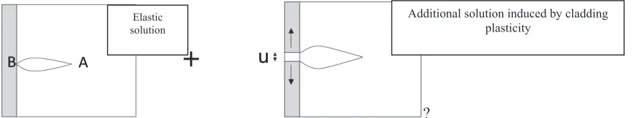
- A specific small scale yielding plastic correction, called Kb solution, has been developed for the calculation of the under-clad defect loading. It takes into account the additional load induced by the plasticity in the cladding, comparable to an imposed opening displacement loading condition on the crack lip, as illustrated in figure 3.
A
B A
+
u
B A
+
B A
B
+
u
?
Figure 3: Physical model of the Kb small scale yielding plastic correction.
10 Conclusions
This paper provides a brief overview of the topics covered by the future AFCEN criteria document on the appendix 5.4, devoted to the fracture mechanics parameters calculation.
This document will provide the technical bases of the proposed solution, some elements on the development history and on the related validation. A complete list of public references will also be provided.
11 References
[1] RSE-M Code, "Rules for In-service Inspection of Nuclear Power Plant Components", 2010 Edition, AFCEN, Paris.
[2] Chapuliot, S., 2000, “Formulaire de KI pour les tubes comportant un défaut de surface
semi-elliptique longitudinal ou circonférentiel, interne ou externe”, CEA-R-5900 report. [3] Raju, I.S. and Newman, J.C., 1981, “An empirical stress-intensity factor equation for the
surface crack”, Engineering Fracture Mechanics, Vol.15, N°1-2, pp.185-192.
[4] Bergman, M., 1995, “Stress intensity factor for circumferential cracked in pipes”. Fatigue
Fract. Eng. Mater. Struct., vol.18, N°10, pp.1155-1172
[5] Miura, N., Takahashi, Y., Shibamoto, H., Kazuhiko, I., “Comparison of stress intensity factor solutions for cylinders with axial and circumferential cracks”, Nuclear Engineering
and Design 238 (2008), pp. 423–434.
[6] Le Delliou, P. and Barthelet, Bruno, 2002, ‘Influence coefficients to calculate stress
intensity factors for an elliptical crack in a plate’, ASME Pressure Vessel and Piping
Conference, Vol. 443, pp. 85-92.
Elastic solution
[7] Marie, S. and Nédélec, N., 2003, “Elastic stresses in elbows submitted to in-plane bending
moment”, Journal of Pressure Vessel Technology, Trans. of ASME, Vol. 125, pp. 209-221. [8] Marie, S., Le Delliou, P., Chapuliot, S. and Kayser, Y., “Stress intensity factor calculation
for surface defects in elbows”, 23th SMIRT conference, Manchester, UK, 2015.
[9] Pellissier-Tanon A., Devaux J.C., Robisson F., "Tear cracking resistance of PWR nozzles",6th SMiRT conference, Paris, France, 1981.
[10] V. Kumar, V., and Shih, C.H.: Fully plastic crack solutions with applications to creep crack growth, International conference in engineering aspects of creep, vol. 1, London,1980 [11] Ainsworth,A.: The assessment of defects in structure of strain hardening material, Eng.
Frac. Mech., vol. 19, n°4, pp633-642, 1984
[12] RCC-MRx Code, 2012 Edition, "Design and Construction Rules for Mechanical Components of FBR Nuclear Islands and high temperature applications" appendix A16, Tome I, vol. Z, Paris, AFCEN, Paris.
[13] www-cast3m.cea.fr [14] www.code-aster.org
[15] www.esi-group.com/SimulationSoftware/Multi_physics/
[16] Chapuliot, S. and Nédélec, M., 2002, Analytical method for the calculation of J parameter on cracked pipes under thermal loading and mechanical plus thermal loading, PVP2002 [17] Marie, S., “Analytical expression of the thermal stresses in a vessel or pipe with cladding
submitted to any thermal transient” – International Journal of Pressure Vessels and Piping, 2004, Vol. 81, pp.303-312
[18] Marie, S. and Chapuliot, S., “Improvement of the calculation of the stress intensity factors for underclad and through clad defects in a reactor pressure vessel submitted to a pressurized thermal shock” –International Journal of Pressure Vessels and Piping, 2008, Vol. 85, pp. 517-531
[19] Lei, Y., and Ainsworth, R.A., 1997, "A J integral estimation method for cracks in welds with mismatched mechanical properties", Int. J. Pres. Ves. & Piping, Vol. 70, pp. 237-245. [20] Le Delliou, P., et al., 2008, "Development of a J-estimation scheme for surface cracks in
piping welds", Proc. ICONE 16 Conference, paper ICONE16-48393