ISSN(Online): 2319-8753 ISSN (Print): 2347-6710
I
nternational
J
ournal of
I
nnovative
R
esearch in
S
cience,
E
ngineering and
T
echnology
(A High Impact Factor, Monthly, Peer Reviewed Journal) Visit: www.ijirset.com
Vol. 6, Issue 10, October 2017
A Study on the diagnostic and fail-safe of the
PMSM
Donghoon Ban*1, Sungho Jin2, Seonghun Lee2
Senior Research Engineer, Convergence Research Centre for Future Automotive Technology, DGIST, Daegu, Korea1 Principal Research Engineer, Convergence Research Centre for Future Automotive Technology, DGIST,
Daegu, Korea2
ABSTRACT:A motor fault must be detected immediately and fault tolerant control is used to significantly reduce the effects from the fault. In this paper, four types of fault are defined and the varied fault tolerant control methods are discussed. Herein, faults are classified in four types: encoder, DC link voltage, DC link current, and phase current. In the case of encoder faults, the hall signal can be used to estimate the rotor position. Fault tolerant control using the defined voltage is performed for a DC link voltage fault. When the DC link current provides a malicious value, the fault tolerant control uses the DC link current, converted from the phase current, and the motor performs in limited mode. Because the phase current has the same RMS and frequency, and a phase difference in a certain place, the difference in the current signal is used to detect the fault. When phase current fault happens, fault tolerant control is performed using the other phase current signals. As a result of this work, the defined fault types could be immediately detected and the fault tolerant control performed without any problems.
KEYWORDS:Fail-safe, BLAC, Motor, DC Link, Phase current, Rotor position.
I. INTRODUCTION
ISSN(Online): 2319-8753 ISSN (Print): 2347-6710
I
nternational
J
ournal of
I
nnovative
R
esearch in
S
cience,
E
ngineering and
T
echnology
(A High Impact Factor, Monthly, Peer Reviewed Journal) Visit: www.ijirset.com
Vol. 6, Issue 10, October 2017
II. RELATEDWORK
In order to measure the rotor position, the encoder and hall sensor are exploited, but these sensors don’t have enough robustness against the noise and external damage. Therefore, many researchers have studied in order to estimate the rotor position without using the encoder and hall sensor. The rotor position is estimated using the fuzzy logic to control the weight of the hall interval. So it’s possible to estimate the rotor position without encoder [1]. The observer method uses the mathematical model of the motor to estimate the rotor position, which requires the accurate motor model. Since the algorithm of sliding mode observer(SMO) is simple and resilient, it is widely used and the performance of SMO depends on the observer model [2, 3]. This paper presents a sliding mode observer for estimating the position and speed of a PMSM [4, 5, 6]. A hybrid terminal SMO method is proposed to achieve sensorless drive for PMSM [7]. And a tuning method is proposed in order to obtain high speed and high accuracy positing system in [8]. In case of the model reference adaptive method, the rotor position is estimated by tuning the model [9]. The authors in [10] estimate the rotor position using EKF and KF requires the accurate model of the system. Therefore, designing the motor is the most important process, which means the better motor modes has the better performance. Besides, the new reduced order EKF for sensorless control method has been studied for the PMSM motor by realizing the EKF with parallel structure. Other researchers propose the method using the back electromotive force to estimate the DC link current and remove the voltage ripple. Authors in [11] developed the control technique using the power feedback in order to limit the fluctuation of the DC link voltage. The new adaptive method to compensate for the ripple of DC link voltage is proposed in [12]. Also the method using the programed PWM wave is studied in order to remove the ripple of the DC link voltage in the operating inverter [13]. By comparing the estimated current and the measured current from the motor, the fault can be diagnosed. The DC link current is used to monitor the short circuit of DC link, short circuit of two output phases and ground or earth faults [14]. The new voltage source inverter without DC link components is suggested. This adjusts sinusoidal AC source current waveforms with appropriate current feedback. Without DC link components whose rectifiers is controlled by suitable current feedback to adjust near sinusoidal AC source current waveforms at unity power factor [15]. The known types of faults are identified by analysing the peak magnitude and frequency of the phase current. To improve the performance of the fault diagnosis, varied parameters are used in [16]. Stator faults, rotor faults, and bearing faults are defined. The faults are diagnosed by thermal monitoring, air gap torque monitoring, noise monitoring, and vibration monitoring. And various analysis methods such as motor current signature analysis, partial discharge, wavelet analysis, expert systems, fuzzy logic, artificial neural network and neural fuzzy system are studied [17].
III.FAULT DIAGNOSIS
3.1 Encoder fault At high speed when there is enough back electromotive force, the sliding mode observer is used to estimate the rotor position. If the difference between the estimated rotor position and the measured rotor position is greater than the predetermined threshold, the system considers that a fault has occurred. Because the back electromotive force at high speed is well estimated, the fault diagnosis method using the sliding mode observer is effective. Equation (1) shows the voltage equation for each phase of the motor. Equation (1) can also be represented as equation (2) and (3) in terms of the current . As shown in the equation (4), the rotor position is estimated using the arctangent of the d and q current. In contrast, the back electromotive force cannot be properly estimated at low speed; so the encoder and hall sensor are exploited for the fault diagnosis. When changing the value of the hall sensor, the number of updated encoder signals is always consistent. However, when the encoder sensor has a fault, the count of measured encoder sensors is different or the count of measured encoder sensors is constant. Therefore, by measuring the count of updated encoder sensors per hall signal, the fault is diagnosed. The relationship between the hall and encoder signals is presented in Fig. 1.
= + + ... (1)
ISSN(Online): 2319-8753 ISSN (Print): 2347-6710
I
nternational
J
ournal of
I
nnovative
R
esearch in
S
cience,
E
ngineering and
T
echnology
(A High Impact Factor, Monthly, Peer Reviewed Journal) Visit: www.ijirset.com
Vol. 6, Issue 10, October 2017
( + 1) = 1− ∙ ( ) + ( )− ( ) ... (3)
= tan ... (4)
Fig. 1. The relationship between the hall and encoder signals
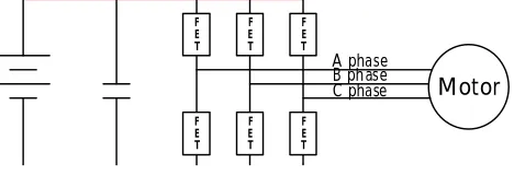
3.2 DC Link voltage fault The structure of the DC link used to operate the motor is presented in Fig. 2. In general, the voltage in the DC link is parallel with the voltage in the FET located at the top and bottom. However, if the energy generated is not provided to the DC link, the generated energy is converted into voltage, which damages the FET. Therefore, the voltage in the DC link must be monitored periodically and managed to keep the voltage within a certain range. When the DC link component has enough capacity, the voltage of the DC link is constant. However, if the capacity is insufficient, the fluctuation of the voltage is significantly influenced by the power generated and consumed.The predefined voltage ranges in the DC link needed for fault diagnosis is 8 to 16V.
Fig. 2. Structure of the DC Link
3.3 DC Link current faultThe total phase current has the same value in the motor as the current measured in the DC link.The phase current measured from the three phases is converted into DC components using the CLARK and PARK transform. The current equation for the motor is expressed as equation (5). Therefore, the DC current calculated using the phase currents are compared with the DC current measured by the current sensors in the DC link. Based on the result, the fault is diagnosed. As shown in equation (6), if the difference between the current measured by the sensor and the current converted from the phase current is greater than 10%, the system considers a fault to be present.
_ = + ... (5)
_ − _ ≥ 10% ... (6)
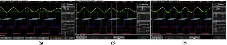
3.4 Phase current fault Because the phase current in the motor is parallel, the sum of three phase current is zero, as in equation (7). In case of normal current, the three phases are parallel and swing 120 degrees, as shown in Fig. 3. Therefore, the RMS value and the peak for each phase are the same. The phase current wave has the different magnitude and frequency according to the speed and load, but the phase current has a phase difference of 120 and 240 degrees at a certain place when the motor rotates. The phase current of the motor has varied fault types, such as the contact between the coil and the battery or ground, and the fault of the phase current sensor. This issue can be addressed using redundancy. In this paper, faults of the phase current sensor are analyzed. If the phase current sensor is not working properly, the current is not parallel, and the RMS and peak value of the three phases of current are different. The normal current swings with a sine wave form while faulty current has a fixed value, or does not have a sine wave form. This difference can be used to diagnose the fault. The normal reference voltage equation of the three phase
Hall si gnal
Enco der s ignal
F E T
Motor F
E T
F E T
F E T F E T F E T
ISSN(Online): 2319-8753 ISSN (Print): 2347-6710
I
nternational
J
ournal of
I
nnovative
R
esearch in
S
cience,
E
ngineering and
T
echnology
(A High Impact Factor, Monthly, Peer Reviewed Journal) Visit: www.ijirset.com
Vol. 6, Issue 10, October 2017
current is expressed as in equation (8). However, when the current value is zero (i.e., = 0), the reference voltage calculated in the field oriented control is expressed as in equation (9). If the voltage for the motor is the same as in equation (9), a fault (i.e., = 0) is detected.
(a) (b) (c)
Fig. 3. (a) The U phase current wave form with hall signal, (b) The V phase current wave form with hall signal, (c) The W phase current wave form with hall signal
+ + = 0 ... (7)
= , = , = ... (8)
= , = , = ... (9)
IV.FAIL-SAFE CONTROL
4.1 Encoder fault When a sensor fault occurs, the fault tolerant control is used to properly operate a system under the fault. At low speed, the fault is diagnosed using the number of hall and encoder signals, and at normal speed, the sliding mode observer is used. When the encoder sensor is not working properly, the hall sensor is exploited to estimate the rotor position and the effectiveness of the method has been validated at varied speeds [18]. Therefore, in the case of an encoder fault, the rotor position is estimated using the hall sensor, which makes the system stable.
4.2 DC Link Voltage fault When the voltage of the DC link is out of its determined range, the fault which presents in a system is detected. However, it is difficult to analyze the cause of the fault with only the generated voltage. Therefore, the system is operated with a limited reference voltage to secure performance, and the voltage in the field oriented control is fixed. When the voltage of the DC link is within normal range, the system considers the state as fault recovery and the voltage reference is not limited anymore.
4.3 DC Link Current fault If the difference between the measured value and the calculated value in the field oriented control is greater than 10%, the system considers that a fault is present. When the phase current is normal, the current sensor in the DC link has the problem. In the case of a fault in the current sensor in the DC link, the DC link current converted from the phase current is used and the current reference is limited in order to make the system stable.
4.4 Phase current fault When using the three phase BLAC motor, the phase current has a phase difference of 120 degrees as shown in equation (10). If the A phase current sensor has a fault, is estimated using the B phase current. The three phases of current used to operate the motor are parallel. According to the speed and the load, the frequency and the RMS value of each is different. However, in a certain place, the value of the frequency and RMS are the same as expressed in equation (11). Therefore, if one of the current sensors is faulty, the value from other phase current sensors is used to estimate the phase current. The estimated phase current is used for the fault tolerant control. This paper does not consider at scenario where both phase current sensors have a fault at the same time.
A Phase
Hall A
Hall B
Hall C
B Phase
Hall A
Hall B
Hall C
ISSN(Online): 2319-8753 ISSN (Print): 2347-6710
I
nternational
J
ournal of
I
nnovative
R
esearch in
S
cience,
E
ngineering and
T
echnology
(A High Impact Factor, Monthly, Peer Reviewed Journal) Visit: www.ijirset.com
Vol. 6, Issue 10, October 2017
= ( − ), = ( ), = ( + )…..(10)
( ) = − ………..(11)
V. SYSTEM STRUCTURE FOR THE EXPERIMENT
The system setup for the experiment is shown in Fig. 4. It consists of a motor controller, a motor, a debugger, a motor load, a switch box, an oscilloscope, and CAN (Control Area Network) monitoring equipment. The D/A (digital to analog) converter implemented in the motor controller had four channels and it monitored variables, such as the rotor position and the value of the current sensor. The analog signal was measured using an oscilloscope and the CAN monitoring equipment monitored the state variables.
Fig. 4. The system structure for the experiment
VI.PERFORMANCE EVALUATION AND RESULTS
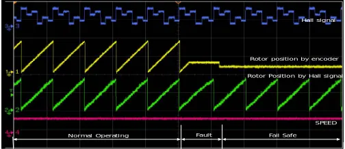
6.1 Fault diagnosis and result of the encoder The experimental structure is constructed to diagnose a fault in the encoder signal. The D/A 1 and 2 show the rotor position by the hall and the encoder signals. The D/A 3 shows the hall signal and the D/A 4 shows the speed of the motor. The fault diagnosis for the encoder sensor is presented in Fig. 5. It also shows the fault tolerant control when the fault happens. In the fault tolerant control, the rotor position from the hall signal is used to operate the motor. After the fault is detected, the fault tolerant control is used; so the speed of the motor hardly changes.In this experiment, we validated the effectiveness of the fault tolerant control using the hall signal to estimate the rotor position when the fault happens in the encoder sensor.
Fig. 5. The fault diagnosis for the encoder sensor scope LOAD MOTOR
CAN Monitoring
SW BOX Debug
Controller & Inverter
Hall signal
Rotor position by encoder
Rotor Position by Hall signal
ISSN(Online): 2319-8753 ISSN (Print): 2347-6710
I
nternational
J
ournal of
I
nnovative
R
esearch in
S
cience,
E
ngineering and
T
echnology
(A High Impact Factor, Monthly, Peer Reviewed Journal) Visit: www.ijirset.com
Vol. 6, Issue 10, October 2017
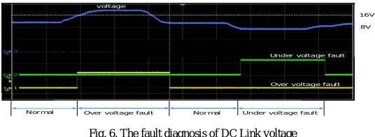
6.2 Fault diagnosis and result of the DC link voltage The magnitude of the voltage in the DC link is adjusted to evaluate the performance of the diagnosis methods. The performance of the fault detection, in relation to the varied magnitude of the voltage in the DC link is presented in Fig. 6. In this figure, the graph indicates the state of the fault diagnosis when the DC link voltage increases and decreases. If a fault occurs in the DC link voltage, the fault tolerant control, for which the predetermined voltage is used regardless of the voltage in DC link, is operated.
Fig. 6. The fault diagnosis of DC Link voltage
6.3 Fault diagnosis and result of the DC link current The current of the DC link is measured on the DC link line using the current sensor, and the DC link current is obtained using the d and q current converted from the phase current. The current in the DC link is presented in Fig. 7. Channel 1 is the DC link current converted from the phase current and channel 2 is the current measured by the current sensor. Channel 3 shows the difference between channel 1 and channel 2. The error status is presented in channel 4. When the fault occurs in the current sensor, the fault tolerant control is used based on the current converted from the phase current.
Fig. 7. The fault diagnosis of DC Link current
6.4 Fault diagnosis and result of the phase current In a certain place, the phase current has the same frequency and RMS value, with a phase difference of 120 degrees. Therefore, if the values of RMS and frequency are different, the system considers that a fault has happened. When is faulty, is used to estimate .
(a) (b)
voltage
Under voltage fault
Over voltage fault
8V 16V
Under voltage fault Over voltage fault Normal
Normal
Estimate current by phase current
DC current by Current sensor
Difference between estimate current and real current
Fault
Normal Operating Fail safe
B phase A phase
C phase
DC current DC current
B phase A phase
ISSN(Online): 2319-8753 ISSN (Print): 2347-6710
I
nternational
J
ournal of
I
nnovative
R
esearch in
S
cience,
E
ngineering and
T
echnology
(A High Impact Factor, Monthly, Peer Reviewed Journal) Visit: www.ijirset.com
Vol. 6, Issue 10, October 2017
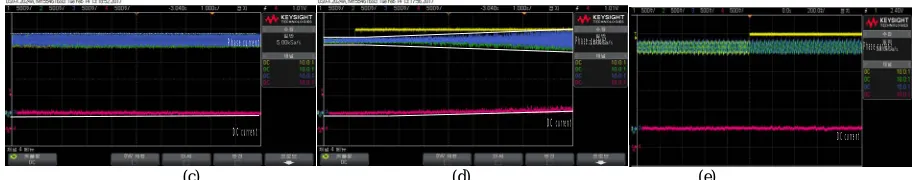
(c) (d) (e)
Fig. 8. (a) A, B, C phase current and dc current in normal status(b) The estimated , B, C phase current and dc currentwhen is faulty, (c) A, B, C phase current and dc current in normal status (d) A, B, C phase current and dc current when is faulty without a fail-safe function, (e) A, B, C phase
current and dc current when is faulty with fail safe function
This is shown in Fig. 8, where channel 1 is , channel 2 is , channel 3 is , and channel 4 is the dc current. If is faulty, vector control for the motor cannot be performed. Therefore, the dc current increases as shown in Fig. 8. (d). However, if the fail-safe function is performed, the dc current is stable as shown in Fig. 8. (e), because the vector control can be normally performed. Therefore, it is confirmed that even though the is faulty, the fault tolerant control can be used to make the system stable. An interpolation is used to compensate the value when is missing.
VII. CONCLUSIONS
In general, a motor is used to drive a dynamic system. Therefore, faults must be detected immediately and fault tolerant control used to significantly reduce the effect of the fault. In this paper, four types of the fault are defined and the varied fault tolerant control methods are discussed. The faults were classified in four types: encoder fault, DC link voltage fault, DC link current fault, and phase current fault. In the case of an encoder fault, the hall signal can be used to estimate the rotor position. The fault tolerant control using the defined voltage is performed in the case of a DC link voltage fault. When the DC link current provides a malicious value, the fault tolerant control uses the DC link current, which is converted from the phase current and the motor performs in limited mode. Because the phase current has the same RMS and frequency, and the phase is different in a certain place, it is possible to use another current signal to detect faults. When a phase current fault happens, fault tolerant control is performed with the other phase current signals. From the proposals in this paper, the defined fault types could be immediately detected and fault tolerant control performed without any problems.
REFERENCES
[1] D. H. Ban, S. H. Lee, and J. S. Hong, “Rotor Position Estimation of Permanent Magnet Synchronous Motors Using Low-Resolution Sensors”,
International Journal of Fuzzy Systems, vol. 19, no. 1, pp. 78-85, 2017
[2] Z. Qiao, T. Shi, T. Wang, Y. Yan, C. Xia, and X. He, “New Sliding-Mode Observer for Position Sensorless Control of Permanent-Magnet
Synchronous Motor”, IEEE Transactions on industrial electronics, vol.60, no.2, pp.710-719, 2013
[3] X. G. Yan, and C. Edwards, “Nonlinear robust fault reconstruction and estimation using a sliding mode observer”, Automatica 43,
pp.1605-1614, 2007
[4] J. I. Ha, K. Ide, T. Sawa, and S. K. Sul, “Sensorless Rotor Position Estimation of an Interior Permanent-Magnet Motor From Initial States”,
IEEE TRANSATIONS ON INDUSTRY APPLICATIONS, vol.39,no.3, pp.761-767, 2003
[5] R. Wu, and G. R. Slemon, “A Permanent Magnet Motor Drive Without a Shaft Sensor”, IEEE TRANSACTION ON INDUSTRY
APPLICATIONS,vol.27,no.5, pp.1005-1011, 1991
[6] C. S. Li, and M. Elbuluk,“A Sliding Mode Observer for Sensorless Control of Permanent Magnet Synchronous Motors”, Industry Applications
Conference, 2001. Thirty-sixth IAS Annual Meeting Conference Record of the 2001 IEEE,vol.1,pp.1273-1278,2001
[7] Y. Feng, J. Zheng, X. Yu, and N. V. Truong, “Hybrid Terminal Sliding-Mode Observer Design Method for a Permanent-Magnet Synchronous
Motor Control System”, IEEE TRANSACTIONS ON INDUSTRIAL ELECTRONICS,vol.56,no.9, pp.3424-3431, 2009
[8] B. K. Kim, W. K. Chung, and K. Ohba, “Design and Performance Tuning of Sliding-Mode Controller for High-Speed and High-Accuracy
Positioning Systems in Disturbance Observer Framework”, IEEE TRANSACTIONS ON INDUSTRIAL ELECTRONICS,vol.56,no.10, pp.3798-3809, 2009
[9] P. Tomei, and C. M. Verrelli, “Observer-Based Speed Tracking Control for Sensorless Permanent Magnet Synchronous Motors With
Unknown Load Torque”, IEEE TRANSACTIONS ON AUTOMATIC CONTROL,vol.56,no.6, pp.1484-1488, 2011 DC current
Phase current Phase current
DC current
DC current Phase current
ISSN(Online): 2319-8753 ISSN (Print): 2347-6710
I
nternational
J
ournal of
I
nnovative
R
esearch in
S
cience,
E
ngineering and
T
echnology
(A High Impact Factor, Monthly, Peer Reviewed Journal) Visit: www.ijirset.com
Vol. 6, Issue 10, October 2017
[10] S. Bolognani, R. Oboe, and M. Zigliotto, “Sensorless Full-Digital PMSM Drive With EKF Estimation of Speed and Rotor Position”, IEEE
TRANSATIONS ON INDUSTRIAL ELECTRONICS,vol.46,no.1, pp.184-191, 1999
[11] J. Yao, H. Li, and Z. Chen,“An Improved Control Strategy of Limiting the DC-Link Voltage Fluctuation for a Doubly Fed Induction Wind
Generator”, IEEE TRANSACTIONS ON POWER ELECTRONICS,vol.23,no.3, pp.1205-1213,2008
[12] F. Blaabjerg, D. O. Neacsu, and J. K. Pedersen, “Adaptive SVM to Compensate DC-Link Voltage Ripple for Four-Switch Three-Phase
Voltage-Source Inverters”, IEEE TRANSACTIONS ON POWER ELECTRONICS,vol.14,no.4, pp.743-752, 1999
[13] P. N. Enjeti, and W. Shireen, “A New Technique to Reject DC-Link Voltage Ripple for Inverters Operating on Programmed PWM
Waveforms”, IEEE TRANSACTIONS ON POWER ELECTRONICS,vol.7,no.1, pp.171-180, 1992
[14] F. Blaabjerg, J. K. Pedersen, U. Jaeger, and P. Thoegersen, “Single Current Sensor Technique in the DC Link of Three-Phase PWM-VS
Inverters: A Review and a Novel Solution”, IEEE TRANSACTIONS ON INDUSTRY APPLICATIONS,vol.33,no.5, pp.1241-1253,1997
[15] K. Iimori, K. Shinohara, O. Tarumi, Z. Fu, and M. Muroya,“New Current-Controlled PWM Rectifier-Voltage Source Inverter without DC
Link Components”, Proceedings of the Power Conversion Conference – Nagaoka 1997,pp.783-786,1997
[16] A. K. Thakur, and P. K. Kundu, “Authentication of unknown fault for a three phase induction motor by stator current spectral analysis”, 2016
2nd International Conference on Control Instrumentation, Energy & Communication(CIEC),pp.279-283, 2016
[17] R. C. Bhavsar, and R. A. Patel, “Various Techniques for Condition Monitoring of Three Phase Induction Motor – A Review”, International
Journal of Engineering Inventions,vol.3,no.4, pp.22-26, 2013
[18] D. H. Ban, J. S. Hong, and S. H. Lee, “Diagnostic of the inverter / the motor using DC current”, Institute of Control, Robotics and system(ICROS 2016), pp.135-136,2016
ACKNOWLEDGMENT
This work was supported by the DGIST R&D Program of the Ministry of Science, ICT and Technology of Korea(grant no. 17-IT-01).
BIOGRAPHY
Donghoon Ban He received the B. S. degrees in electrical engineering from Donga University, Busan, Korea in 1999; the M.S. degree in electrical engineering from Pusan University, Busan, Korea in 2006; and the Ph. D. degree in electrical engineering from Donga University, Busan, Korea in 2013. He is a senior research engineer at Daegu Gyeongbuk Institute of Science & Technology(DGIST). He is developing the components of vehicles such as Body Control Module, Electronic Parking Brake, and Electronic Mechanical Brake base on AUTOSAR. His research interests are Fuzzy control, PMSM control, inverters and AUTOSAR.
Sungho Jin He received the B. S. degrees in electrical He received the B.S. and M.S. degrees in electronics engineering from Kyungpook National University, Daegu, Korea, in 1989 and 1991, respectively.e is a Principal Research Engineer with the Daegu Gyeongbuk Institute of Science and Technology, Daegu, Korea. His research interests include automotive embedded systems, modeling and simulation for electric vehicles, and motorapplication systems.