Article
1
Experimental Study on Drilling MDF with Tools
2
Coated with TiAlN and ZrN
3
Krzysztof Szwajka 1,*, Joanna Zielińska-Szwajka 1 and Tomasz Trzepiecinski 2
4
1 Faculty of Mechanical Engineering and Technology, Rzeszow University of Technology,
5
Kwiatkowskiego 4, 37-450 Stalowa Wola, Poland; [email protected]
6
2 Department of Materials Forming and Processing, Rzeszow University of Technology,
7
Powstancow Warszawy 8, 35-959 Rzeszow, Poland; [email protected]
8
* Krzysztof Szwajka: [email protected]; Tel.: +48-695-695-456
9
10
Abstract: There is increasing use of wood-based composites in industry not only because of the
11
shortage of solid wood, but above all for their better properties such as: strength, aesthetic
12
appearance, etc. compared to wood. Medium density fibreboard (MDF) is a wood-based composite
13
that is widely used in the furniture industry. The goal of the research conducted was to determine
14
the effect of the type of coating on the drill cutting blades on the value of thrust force (Ft), cutting
15
torque (Mc), cutting tool temperature (T) and surface roughness of the hole in drilling MDF panels.
16
In the tests three types of carbide drills (HW) were used: not coated, TiAlN coated and ZrN coated.
17
The measurement of both the thrust force and the cutting torque was carried out using an industrial
18
piezoelectric sensor. The temperature of the cutting tool in the drilling process was measured using
19
an industrial temperature measurement system using a K-type thermocouple. It was found that the
20
value of the maximum temperature of the tool in the drilling process depends not only on the cutting
21
speed and feed rate, but also on the type of coating of the cutting tool. The value of both the cutting
22
torque and the thrust force is significantly influenced by the value of the feed rate and the type of
23
drill coating. The effect of varying plate density on the surface roughness of the hole and the
24
variation of the value of the thrust force is also discussed. The results of the investigations were
25
statistically analysed using a multi-factorial analysis of variance (ANOVA).
26
Keywords: drilling MDF; thrust force; cutting temperature; surface roughness; cutting tool coating
27
28
1. Introduction
29
Medium density fibreboard (MDF) is a wood-based product widely used in the furniture
30
industry [1-5]. MDFs are composed of wood fibres, bonded with formaldehyde glue under the
31
influence of heat and pressure. The use of medium density fibreboards in industry is associated with
32
their machining during furniture production. One of the most commonly used operations in the
33
production of MDF furniture is drilling. The MDFs machinability is determined by the quality of the
34
surface [5, 6], which largely depends on the degree of tool wear and the mechanism of chip formation
35
[7]. Various studies have been carried out to improve understanding of MDF cutting characteristics
36
[4, 8-10]. Most of the studies are mainly focused on measuring the cutting forces and the friction
37
phenomenon based on the theory used in the cutting process of metals [11, 12]. Cutting forces,
38
temperature and surface roughness that reflect susceptibility to material processing are three
39
important issues in the machining of wood-based materials. Cutting forces have a direct effect on
40
energy consumption, tool wear, heat generation and the quality of the surface machined [13-15].
41
In order to maintain the relatively long service life of cutting tools used for MDF machining, it
42
is necessary to use tools with a high wear resistance. Blades made from HM cemented carbide or
43
diamond are the most commonly used in the machining of wood-based materials. In the literature
44
durability of the cutting tool blades by applying various coatings to the blade surfaces in order to
47
reduce their wear [16-22]. Recently, this field of research has been developing dynamically. However,
48
the use of cutting tools with new coatings requires a number of tests, within which the quality of the
49
surface machined, the cutting temperature and the cutting resistance are assessed. The drilling
50
process in metals has been widely studied, and the results of these tests are well described in the
51
literature, while the process of drilling MDF has not received much attention [5, 15, 23, 24].
52
The cutting process of wood-based materials is strictly dependent on their physical and
53
mechanical properties. MDF has a more homogeneous structure than solid wood. While solid wood
54
exhibits anisotropic properties, MDF consists of several isotropic layers [25] where the highest
55
density is observed at the edges of the panel, and the lowest density is in the middle of the panel.
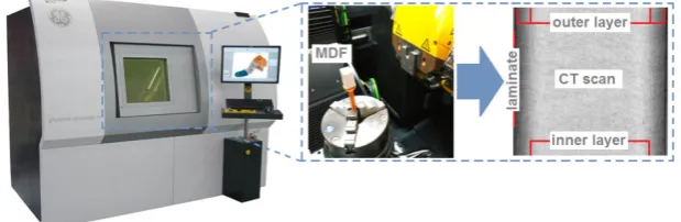
56
Gordon and Hilery [10] presented a brief overview of work on forecasting the cutting forces in
57
MDF machining. These works described the general mechanics of MDF machining based on
58
assumptions occurring in metalworking. Djouadi et a. [17] investigated the use of polycrystalline
59
diamond (PCD) cutting blades in MDF machining. They concluded that the main benefit of using
60
PCD is the extended durability of the cutting tool resulting from its greater hardness and better
61
tribological properties compared to traditional tool materials. Davim [2] studied the effect of various
62
cutting parameters on surface roughness in the MDF milling process using uncoated cutting tools.
63
Similar studies were carried out by Sedlecký [23].
64
Szwajka and others [15] conducted investigations of the drilling of melamine faced chipboard
65
using a carbide drill. They developed an analytical model for predicting the effect of drilling
66
parameters on thrust force. It was found that an increase in the value of the feed rate increases
67
delamination of the chipboard.
68
The quality of the MDF surface is an important factor influencing the final appearance of the
69
product or subsequent technological processes, such as gluing (adhesion and cohesion), coating,
70
varnishing, etc. [23, 26]. The surface roughness of the surface machined depends on various factors
71
and conditions [2, 24, 27], which can be classified as follows: type of machining (cutting, milling,
72
drilling, etc.) [28-30], machining parameters (cutting speed, feed rate) [31-34], type of cutting tool
73
(geometry, applied coatings on the cutting edge), as well as the properties of the material being
74
processed [26].
75
Even if the machining parameters are the same, each machining method leaves characteristic
76
irregularities on the surface; for example, saw cut surfaces differ from milled surfaces [8, 33]. The
77
requirements for surface roughness are determined in accordance with the functional application of
78
the future product [36, 37]. The surface roughness is determined by specifying the numerical value
79
of one or several surface roughness parameters and the value of the sampling length [23].
80
Lin et al. [36] analysed the machinability of MDFs. They used a digital camera to record chip
81
formation occurring in front of the cutting tool edge and a scanning electron microscope (SEM) for
82
additional analysis of the surface machined. Davim et al. [38] studied the the cutting parameters
83
(cutting velocity and feed rate) under specific cutting pressure, thrust force, damage and surface
84
roughness in glass fibre reinforced plastics. It was shown that the differences in MDF panel density
85
are closely related to machinability characteristics.
86
The heat generated in the drilling process has a direct effect on the surface roughness of the
87
surface machined, hole quality and chip morphology [1, 39]. The temperature in the region of contact
88
of the blade with the material processed (wood or wood-based material) depends both on the energy
89
released in this region and the efficiency of heat removal in this region. In addition to radiation,
90
conductivity is the main mechanism responsible for heat removal. Considering the fact that the
91
thermal conductivity of wood and wood-based materials is very low, and the use of cooling liquids
92
is excluded, the main element responsible for heat removal is the tool. This leads to an undesirable
93
increase in tool blade temperature. During the drilling process, the most important factor affecting
94
the cutting output is the temperature created between the cutting tool and the workpiece. In this
95
paper the effect that the type of coating on the drill cutting blades has on the value of thrust force,
cutting torque, cutting tool temperature and surface roughness of the hole in drilling MDF panels is
97
investigated. Three types of carbide drills (HW) were used in the tests: not coated, TiAlN coated and
98
ZrN coated.
99
2. Experimental Procedure
100
2.1. Material
101
A typical industrial MDF panel with a thickness of 18 mm was used as the workpiece. The
102
mechanical and physical properties of the material being processed are listed in Table 1. An MDF
103
panel is characterised by a clear differentiation of material density in the cross-section, which results
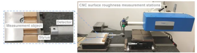
104
from its multi-layered structure. To more accurately characterise the workpiece, a laboratory
105
measurement of the density profile through the panel thickness was carried out using a Phoenix
v-106
tomome x-ray tomograph (GE Sensing & Inspection Technologies, Wunstorf, Germany).
107
Table 1. Selected mechanical and physical properties of MDF.
108
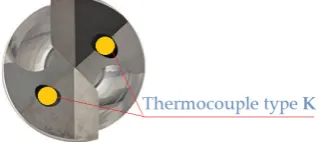
Density (kg/m3)
Moisture content
(%)
Bending Strength (MPa)
Elasticity Modulus (MPa)
Thermal Conductivity
(W/m*K)
Thermal Expansion
(µm/m*K)
742 7.2 38 2530 0.3 12 X-ray tomographs permits one to obtain tomographic images of the object examined, and then
109
present its spatial (3D) image from many flat (2D) images taken in various positions. The computer
110
tomographic (CT) images contain information about the location and density of the absorbing
111
features in the object. Any difference in material density inside the object can be measured and
112
visualised. Figure 1 shows a picture of the cross-section of an MDF panel, in which a distinct variation
113
in plate density can be observed. The highest density occurs in the outer layers of the panel (to a
114
depth of about 2.3 mm). However, a lower density appears in the inner layer (around 13.4 mm in
115
length) (Figure 1).
116
Figure 1. MDF density measurement on a computer tomography Phoenix v|tome|x m.
117
Furthermore, the hardness distribution of the material processed was measured using a Shore
118
hardness tester (Hildebrand, Oberboihingen, Germany) using the Shore D scale (Figure 2b). As can
119
be seen, the hardness distribution (Figure 2a) is closely related to the density profile. The highest
120
hardness value occurs in the outer layers with a thickness of approximately 2.3 mm and is equal to
121
62°Sh (D scale). As we move away from the outer layer, the hardness decreases, reaching a value of
122
43°Sh (D scale) at a depth in the range between 7 mm and 11 mm.
(a)
(b)
Figure 2. Hardness measurement: (a) Hardness profile of MDF used in tests; (b) Shore hardness
124
tester.
125
The spectral analysis of the elements constituting the material (Figure 3) was carried out using
126
a scanning electron microscope (TESCAN, MIRA3, Brno, Czech Republic).
127
(a) (b) (c)
Figure 3. Scanning electron microscope and spectral analysis of the MDF: (a) Measuring stand; (b)
128
Microphotograph of an MDF panel surface; (c) Spectra of the outer surface of an MDF panel.
129
2.2. Cutting tools
130
In the drilling of MDFs, HW sintered carbide cutting tools were used with different types of
131
cutting blade coating. Two types of coating for cutting blades, i.e. TiAlN and ZrN were used. The
132
selection of coatings was dictated by the fact that they belong to those most commonly used in the
133
machining of composite materials [40]. In the case of cutting wood-based materials, there is a general
134
lack of commercially available cutting tools (especially drills) with additional protective coatings. In
135
the research it was necessary to measure the temperature of the cutting blade during the drilling
136
process. To measure the temperature between the cutting edge and the workpiece using
137
thermocouples, it was necessary for the tool to have coolant channels. However, no cooling liquids
138
are used in the treatment of MDFs. So, it was necessary to fabricate drills. The geometry of the drills
139
was based on the geometry of the Leitz® HW / D10 / NL35 / S10x24 / GL70 drill (Leitz GmbH & Co.
140
KG, Oberkochen, Baden-Württemberg, Germany), which is widely used in the drilling of
through-141
holes in MDFs.
142
A coordinate measuring machine is used to measure the geometrical dimensions of the reference
143
tool in order to make drills with coolant channels identical to the standard ones but made of cemented
144
carbide monolith, which will be covered with two different coatings. The Zoller® Genius 3 coordinate
145
measuring machine (Zoller, USA) (Figure 4) was used to measure and control the geometry of the
146
cutting tools. This machine is used by tool manufacturers to enable one to take measurements in a
147
fully automatic way. Fully automatic precise measurements are assured by 5 numerically controlled
148
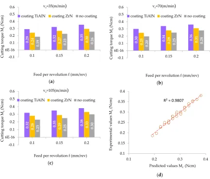
axes (X, Y, Z, C, B).
149
20 30 40 50 60
0 2 4 6 8 10 12 14 16 18
Shore D
Hardness
(°Sh)
The Genius 3 device is equipped with an optical system of two cameras: a main camera for
150
measurement in transmitted and reflected light with a magnification of 50x and a tilt camera for
151
measuring only in reflected light with a lens capable of focusing in 3D mode with a magnification of
152
200x. To accurately capture the details of the cutting blade, the device is equipped with eight-segment
153
automatically tuned LED lighting.
154
(a) (b)
Figure 4. Measuring the cutting tool: (a) The Zoller Genius 3 coordinate measuring machine; (b) The
155
mounting arrangements and optical system in the Zoller® Genius 3.
156
The computer-aided design of the tool was developed in the Numroto® Plus program (NUM
157
AG, Teufen, Switzerland). Numroto Plus software is commonly used to design rotary cutting tools
158
and to generate a 3D model (Figure 5c) after prior definition of all the geometrical values of the cutting
159
tool, the selection of the type of grinding wheels and workpiece size, and the setting of machining
160
parameters on a numerically controlled grinder. The grinding wheels used in the fabrication of drills
161
are Toolgal® diamond grinding wheels (TOOLGAL Industrial Diamonds Ltd., Degania, Israel). Two
162
1A1 grinding wheels and two types 11V9 and 12V9 were used for the fabrication of drills.
163
The finished project made in the Numroto® Plus program was exported to the 5-axes grinder
164
from a Saacke® model UW IF (SAACKE GmbH & Co. KG, Pforzheim, Germany), shown in Figures
165
5a and 5b.
166
(a) (b) (c)
Figure 5. Grinder with drill design: (a) SAACKE CNC-Grinding Center Model UW I F; (b) work-space
167
of the grinder; (c) drill design in the Numroto® Plus program.
168
An effective way to increase the durability of cutting tools is to apply a coating on their blades.
169
The most commonly used method is Physical Vapour Deposition (PVD) in which the solid metal is
170
vapourised in a high vacuum environment and deposited in the form of a thin layer on the tool
171
surface. The deposited layer, usually with a thickness of 3 ÷ 5 µm, has a very high hardness, usually
172
in the range of 2000÷3000 HV, which significantly increases the resistance of the tool blades to
173
abrasive wear. The machined tools (Figure 6b) were PVD coated with zirconium nitride (ZrN) and
174
aluminum titanium nitride (TiAlN) using an EIFELER VACOTEC PVD Alpha 400 vacuum reactor
175
(Figure 6a).
(a)
(b)
Figure 6. Stand for applying protective coatings: (a) Vacuum reactor EIFELER VACOTEC PVD Alpha
177
400 ; (b) Drills with the coatings used in the research.
178
The coatings were made on a substrate previously sprayed with high energy ions, free of oxides
179
and enriched with elements forming a strong adhesion-diffusion bond. The selected properties of the
180
coatings used are listed in Table 2.
181
Table 2. Selected mechanical and physical properties of the coatings.
182
Type of coating
Coating Temperature
(°C)
Hardness (HV)
Thickness (µm)
Coefficient of Friction
Thermal Conductivity
(W/m*K)
ZrN 350-500 2200 2-3 0.4 0.28
TiAlN 400-500 3000 2-3 0.6 2.48
Three types of drills with coolant channels were fabricated: an HW carbide drill with a ZrN
183
coating, an HW carbide drill without a coating and an HW carbide drill with a TiAlN coating (Figure
184
6b). The spectral analysis of the elements included in the coating applied (Figure 7) was carried out
185
using a TESCAN® scanning electron microscope (TESCAN, MIRA3, Brno, Czech Republic).
186
(a) (b)
Figure 7. Results of spectral analysis of the drills: (a) ZrN coated drill; (b) TiAlN coated drill.
187
2.3. Equipment and Machining Conditions
188
The drilling process was carried out in two stages: on a CNC vertical milling machine and on an
189
EMCO® CNC lathe (EMCO GmbH, Hallein, Austria). A schematic diagram of the configuration of
190
the measurement path and the measurement data archiving system is presented in Figure 8. In the
191
first stage of testing, the CNC milling machine recorded the values of thrust force (Ft) and cutting
192
194
Figure 8. Experimental set-up and schematic diagram of the data acquisition system.
195
In the first stage, three holes (with the same set of cutting parameters) were drilled in an MDF
196
panel with dimensions 130 × 30 × 18 mm on a CNC milling machine. The value of the thrust force and
197
the cutting torque was measured using the Kistler® 9345B2 piezoelectric industrial sensor (Kistler,
198
Winterthur, Switzerland). The signals from the sensor were recorded on a personal computer (PC)
199
disk via the National Instruments® 6034E (Austin, TX, USA) 16-bit analogue-to-digital card with a
200
sampling rate of 50 Hz. The surface topography of each completed hole was measured in two
201
locations (every 180°) using the Hommel-Etamic T8000RC CNC profilometer (Jenoptik, Jena,
202
Germany) (Figure 9). In order to measure the surface roughness, the test sample was cut into two
203
parts along the hole axis. One measurement was made for each part separately.
204
205
Figure 9. Measurement of surface topography.
206
In the second stage of the investigations, the holes were drilled (with the same set of cutting
207
parameters) in MDF workpieces with a diameter of 30 mm and a thickness of 18 mm on a CNC lathe.
208
The temperature value was measured during machining between the cutting edge and the workpiece
209
using the National Instruments® 9212 industrial system (Austin, TX, USA). Two K-type
210
thermocouple wires with a diameter of 0.2 mm were used for temperature measurement. The
211
thermocouple wires were mounted in the cooling liquid drill channels (Figure 10). Signals from the
212
measurement system were recorded in digital form on a personal computer (PC) disk. The sampling
213
rate of signals during experiments was 5 Hz, and a 24-bit measurement card was used.
215
Figure 10. Drill with inserted thermocouples.
216
The cutting parameters used during the drilling experiments are listed in Table 3. Three
217
replications were made for each of the sets of cutting parameters. This research methodology was
218
applied to drilling with the following types of drills: not coated, ZrN coated and TiAlN coated.
219
Table 3.Machining conditions.
220
Cutting speed (m/min)
Feed per revolution (mm/rev)
Feed rate (mm/min)
Rotational speed of drill (rev/min)
35 0.10 111 1114
35 0.15 167 1114
35 0.20 222 1114
70 0.10 222 2229
70 0.15 334 2229
70 0.20 445 2229
105 0.10 334 3344
105 0.15 501 3344
105 0.20 668 3344
3. Results
221
3.1. Feed force and cutting torque
222
Figure 11 shows the variation in thrust force, cutting torque and cutting edge temperature as a
223
function of cutting length when drilling the MDF at a cutting speed of 35 m/min and a feed rate of
224
167 mm/min using the TiAlN coated drill.
225
226
Figure 11. Variation of thrust force, cutting torque and temperature in the drilling process.
It was observed that five major phases of the variation of the thrust force (Ft) value can be
228
identified during drilling (Regions I-V in Figure 11). In the period referred to as Phase I, the chisel
229
edge of the drill penetrates into the material producing a rapid increase in the value of the thrust
230
force. During this phase, instead of cutting, the chisel edge of the drill is pressed into the material.
231
Then the drill starts to cut the outer layer of the material with the highest density and hardness. When
232
the chisel edge of the drill leaves the area of material with the highest density (depth approx. 2.2 mm),
233
the force value decreases due to the fact that the drill sinks into the middle layer of the panel with
234
lower density and hardness. During Phase II the drill penetrates to a depth of h = 8.1 mm, which is
235
equal to the height of the cutting blades of the drill (Figure 5c). During this time, there is an increase
236
in the cross-sectional area of the cutting layer, which results in a proportional increase in the thrust
237
force. Phase III corresponds to cutting with a constant cross-section of the cutting layer in the middle
238
layer of the panel. Stabilisation of the thrust force value is then observed. At the beginning of Phase
239
IV, the value of the thrust force starts to increase rapidly due to the fact that the drill begins to
240
penetrate the outer layer of the material (higher density and hardness). The thrust force reaches its
241
maximum value. When the chisel edge of a drill leaves the workpiece (cutting path approx. 18 mm),
242
the thrust force starts to decrease (Phase V). The value of the thrust force drops to zero at the end of
243
Phase V when the cutting edges of the drill have left the workpiece.
244
In the case of cutting torque (Mc), it is clearly visible in Phase 1 that there is no machining, and
245
only the chisel edge of a drill is pressed into the workpiece. In Phase I the cutting torque value is close
246
to zero. Next, the blades sink into the workpiece (Phase II) which results in a proportional increase
247
in the value of cutting torque. The period of this increase continues until the drill reaches the
248
maximum cross-sectional area of the cutting layer, i.e. the drill is penetrated to a depth of h = 8.1 mm.
249
In Phase III, the cutting of the cutting layer with a constant cross section in the middle layer of the
250
panel proceeds. A stabilisation of the cutting torque value is observed. At the beginning of Phase IV
251
the value of the cutting torque starts to increase due to the fact that the drill begins to enter into the
252
outer layer of material (higher density and hardness). Furthermore, in this phase the largest
cross-253
section of the material is cut and the cutting torque reaches its maximum value. When the drill begins
254
to come out of the workpiece (cutting path approx. 18 mm), the cutting torque starts to decrease
255
(Phase V). In the middle part of Phase V, some stabilisation of the cutting torque is observed. As a
256
result the drill that comes out of the material cuts only the outer layer of the material characterised
257
by high density and hardness. The cutting torque value drops to zero at the end of Phase V when the
258
cutting edges of the drill have left the workpiece. For the analysis of the acquired signals of Ft and
259
Mc, an individually designed computer program was prepared in the LabVIEW programming
260
language enabling, at selected time intervals, the mean values of the recorded thrust force and cutting
261
torque signals to be determined. The program was based on the automatic determination of values
262
of Ft and Mc parameters in a specific time range of the signal. The methodology for determining the
263
average values of recorded signals has been described in detail in [5]. Figures 12a-c show the effect
264
of feed per revolution (f) on the thrust force (Ft) for the three cutting speeds and the three types of
265
drill coating. The thrust force values presented in the graphs were obtained as the average result of
266
three repetitions.
267
Multi-factorial analysis of variance (ANOVA) carried out in the STATISTICA program allowed
268
the verification of the significance of the influence of several independent variables on the dependent
269
variable. Furthermore, multivariate analysis makes it possible to take the synergistic effect of the
270
product of many variables into account in the statistical model. Taking into account the adopted level
271
of significance of p = 0.05, the statistical significance of particular groups of variables and individual
272
variables is determined. The results of the analysis (Table 4) allow one to reject, at a significance level
273
p = 0.000, the hypothesis concerning the lack of effect of the factors "coating", feed per revolution (f)
274
and cutting speed (vc) on the value of the thrust force (Ft). There was no statistically significant effect
275
of interactions between the factors analysed.
(a) (b)
(c) (d)
Figure 12. Influence of the feed value on the value of the thrust force: (a) for cutting speed 35 m/min;
277
(b) for cutting speed 70 m/min; (c) for cutting speed 105 m/min; (d) correlation between the
278
experimental and predicted values of thrust force.
279
Table 4.Significance level of the effect of cutting parameters on the average thrust force (Ft).
280
Tests Applied Level of Significance (p ≤0.05)
cutting speed (vc) 0.000
feed per revolution (f) 0.000
coating 0.000
coating*cutting speed 0.997
coating*feed per revolution 0.564
The smallest value of thrust force (Ft) was obtained in the drilling process using a tool without
281
a coating. However, the highest values of thrust force were obtained for a drill with a TiAlN coating.
282
The increase in the value of the thrust force in comparison to machining without a coating was on
283
average about 39%. In the case of a ZrN coated drill, the value of the thrust force obtained was
284
reduced in comparison to the TiAlN coated drill, but it was still higher on average by about 17% in
285
relation to the value obtained with the use of a drill without a coating. For example: for the cutting
286
speed vc = 105 m/min and feed per revolution value f = 0.2 mm/rev the value of the thrust force for
287
the TiAlN coated drill was 33 N, for the tool with a ZrN coating was 27.8 N and for the tool without
288
a coating it was 23.7 N. This can be explained by the differing values of the coefficient of friction
289
between the tool and the workpiece material resulting from the type of coating used. For all the
290
coatings used, the value of the thrust force increases with an increase in the value of the feed per
291
revolution. The value of the thrust force can be described by the equations (1-3).
292
24.2 29.2 26.8 29.6
32.3 35.4
18.6 22.7
25.7
0 5 10 15 20 25 30 35
0.1 0.15 0.2
Th
rus
t
Force F
t
(N
)
Feed per revolution f (mm/rev) coating ZrN coating TiAlN no coating
23.7 28.8 26.3 29.2
31.4 34.1
17.7 20.2
24
0 5 10 15 20 25 30 35
0.1 0.15 0.2
Th
rus
t
Force F
t
(N
)
Feed per revolution f (mm/rev) coating ZrN coating TiAlN no coating
23.6 28.8 25.4 27.8
30.7 33
17.1 20.6
23.7
0 5 10 15 20 25 30 35 40
0.1 0.15 0.2
Th
rus
t
Force F
t
(N
)
Feed per revolution f (mm/rev) vc=105(m/min)
coating ZrN coating TiAlN no coating
R² = 0.9903
15 20 25 30 35 40
15 20 25 30 35 40
Ex
pe
ri
me
nta
l va
lu
es
Ft
(N
)
Ft (N) = 25.139 + 52.333*f – 0.021*vc , (ZrN) (1)
Ft (N) = 20.005 + 50.333*f – 0.018*vc , (TiAlN) (2)
Ft (N) = 13.011 + 66.667*f – 0.026*vc , (no coated) (3)
Figure 12d presents a comparison between the results for the values of the thrust force obtained
293
during the experiment with the values obtained based on the analytical model (1). The correlation
294
coefficient obtained was equal to R2 = 0.9903. Figures 13a-c shows the relations of cutting material
295
(Mc) versus the feed per revolution (f) for the three cutting speeds (vc) and three types of drill coatings.
296
The influence of these parameters on the cutting torque (Mc) is noticeable to a lesser extent.
297
(a) (b)
(c)
(d)
Figure 13. Influence of the feed value on the value of the cutting torque: (a) for cutting speed 35 m/min;
298
(b) for cutting speed 70 m/min; (c) for cutting speed 105 m/min; (d) correlation between experimental
299
and predicted values of cutting torque.
300
The results of the statistical analysis (Table 5) allow one to reject, at the level of significance p =
301
0.000, the hypothesis that the coating type, feed per revolution (f) and cutting speed (vc) do not affect
302
the value of the cutting torque (Mc). In the case of interactions between the factors analysed, no
303
statistically significant effect of these factors on the value of (Mc) was observed.
304
305
0.
29 0.32 0.35
0.
24 0.27 0.30
0.
19 0.23 0.26
-0.1 6E-16 0.1 0.2 0.3 0.4 0.5 0.6
0.1 0.15 0.2
Cutti ng to rq ue M c (N cm)
Feed per revolution f (mm/rev) vc=35(m/min)
coating TiAlN coating ZrN no coating
0.
30 0.34 0.36
0.
25 0.28 0.31
0.
20 0.25 0.28
-0.1 6E-16 0.1 0.2 0.3 0.4 0.5 0.6
0.1 0.15 0.2
Cutti ng to rq ue M c (N cm)
Feed per revolution f (mm/rev) vc=70(m/min)
coating TiAlN coating ZrN no coating
0.
32 0.35 0.38
0.
28
0.
29 0.33
0.
23 0.25 0.30
-0.1 6E-16 0.1 0.2 0.3 0.4 0.5 0.6
0.1 0.15 0.2
Cutti ng to rq ue M c (N cm)
Feed per revolution f (mm/rev) vc=105(m/min)
coating TiAlN coating ZrN no coating R² = 0.9807
0.1 0.15 0.2 0.25 0.3 0.35 0.4
0.1 0.2 0.3 0.4
Ex pe ri me nta l va lu es M c (N cm)
Tests Applied Level of Significance (p ≤0.05)
cutting speed (vc) 0.000
feed per revolution (f) 0.000
coating 0.000
coating*cutting speed 0.853
coating*feed per revolution 0.734
The lowest value of torque was obtained using the drill without a coating in the drilling process
307
(Figure 13). The highest values of cutting torque (Mc) recorded in the experiments were obtained
308
using a drill with a TiAlN coating. The increase in the value of cutting torque when machining using
309
coated drills in comparison to that using an uncoated drill was approximately 35%. In the case of a
310
ZrN coated drill, the value of the cutting torque (Mc) obtained was less than that using a TiAlN coated
311
drill, but it was still greater by approx. 15% in relation to the value of (Mc) obtained with a drill
312
without a coating.
313
For example: for the cutting speed vc = 35 m/min and feed per revolution value f = 0.2 mm/rev
314
the cutting torque (Mc) for the TiAlN coated drill was 0.35 Ncm, for the ZrN coated drill it was 0.3
315
Ncm and for the drill without coating was 0.26 Ncm. In a similar manner to the effect of drilling
316
parameters on the value of the thrust force, this fact can be explained by the differing values of the
317
coefficient of friction between the tool and the workpiece resulting from the type of drill coating. For
318
all the coatings used, the value of the thrust force (Ft) increases with an increase of the feed per
319
revolution (f) value. The value of the thrust force (Ft) can therefore be described by the equations
(4-320
6).
321
Mc (Ncm) = 0.218 + 0.607*f – 0.001*vc , (ZrN) (4)
Mc (Ncm) = 0.167 + 0.557*f – 0.001*vc , (TiAlN) (5)
Mc (Ncm) = 0.093 + 0.747*f – 0.001*vc , (no coated) (6)
Figure 13d shows a comparison of the results of the cutting torque values obtained during the
322
experiment with the values obtained on the basis of the analytical model. A correlation coefficient R2
323
= 0.9807 was obtained between the experimental and predicted values of cutting torque (Mc). For all
324
the coatings of tools used, the value of the cutting torque (Mc) increases as the feed per revolution (f)
325
increases.
326
3.2. Analysis of Surface Topography
327
Surface topography is one of the main features taken into account to evaluate the surface quality
328
in machining processes. The value of the roughness average Ra parameter was measured in the
329
longitudinal direction of the holes machined in MDF panels. The choice of this indicator to assess
330
surface roughness was dictated by its very frequent use in production plants [23]. The value of the
331
roughness average (Ra) was determined on the basis of the surface topography map in selected
332
measurement sections. Figures 14a-c show an example of the topography of the hole surface obtained
333
in the process of drilling with a TiAlN coated drill at a cutting speed of 105 m/min and with three
334
feed per revolution values.
335
Three areas with a different character of surface roughness can clearly be seen on the surface
336
topographies presented. The first and the second area occur in the outer layers of the MDF panel and
337
the third area in the middle layer of the board. This diversity can be explained by the abovementioned
338
multi-layered structure of the MDFs. The resulting surface topography accurately reflects changes in
339
both hardness and panel density.
(a) (b)
(c)
Figure 14. The topography of the surface drilled with a TiAlN coated tool: (a) cutting speed 105 m/min
341
and feed per revolution 0.1 mm/rev; (b) cutting speed 105 m/min and feed per revolution 0.15 mm/rev;
342
(c) cutting speed 105 m/min and feed per revolution 0.2 mm/rev.
343
Measurement of the roughness average (Ra) parameter was carried out in accordance with the
344
recommendations of ISO-4288:2011. The test conditions of the surface roughness measurement were
345
adopted in accordance with Table 6. The mean groove spacing (RSm) value (Figure 15) in the
346
measurements was in the range between 0.13 and 0.4.
347
Table 6. Setup for the roughness measurement (EN ISO 4288).
348
Mean Groove Spacing for Periodic Profiles RSm
(mm)
Measurement parameter
λc = lc (mm)
ln (mm)
lt (mm)
rtip (µm)
0.013 < RSm ≤0.04 0.08 0.4 0.48 2
0.04 < RSm ≤ 0.13 0.25 1.25 1.5 2
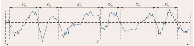
0.13 < RSm ≤ 0.4 0.8 4 4.8 2 or 5
0.4 < RSm ≤ 1.3 2.5 12.5 15 5
1.3 < RSm ≤4 8 40 48 10
rtip maximum probe tip radius, lr sampling length, ln evaluation length, lt stylus travel
349
(evaluation.length plus start and finish lengths).
350
351
Figure 15. The mean groove spacing RSm as the mean value of the spacing Xsi of the profile
352
elements.
353
The value of the Ra roughness average parameter was determined separately for the outer layer
354
and middle layer of the MDF. Therefore, the additional effect of both the density and hardness of the
355
workpiece on the Ra parameter can be analysed.
356
Figures 16 and 17 show the effect of the feed per revolution value for the three cutting speeds
357
and all types of tool coatings. The values of roughness average (Ra) in Figures 16 and 17 are the
358
average of six measurements. As mentioned, two measurements were made for each hole, and the
(a) (b)
(c)
(d)
Figure 16. Influence of the feed value on the value of the surface roughness in the inner layer: (a) for
362
a cutting speed of 35 m/min; (b) for a cutting speed of 70 m/min; (c) for a cutting speed of 105 m/min;
363
(d) measurement area.
364
Figure 17 presents the results regarding the measurement of surface roughness in the outer layer
365
of the workpiece. In both cases, as the cutting speed (vc) increases and simultaneously the feed per
366
revolution (f) decreases, the value of the roughness average (Ra) decreases. For the inner layer of
367
panel at a cutting speed of 35 m/min and a feed per revolution of 0.2 mm/rev, the roughness average
368
parameter was Ra = 10.3 µm for a TiAlN coated drill, for a cutting speed of 105 m/min and a feed per
369
revolution of 0.1 mm/rev, the roughness average parameter was Ra = 6.6 µm. However, for the outer
370
layer of the panel at a cutting speed of 35 m/min and a feed per revolution of 0.2 mm/rev, the
371
roughness average parameter was Ra = 5.1 µm, while for a cutting speed of 105 m/min and a feed per
372
revolution of 0.1 mm/rev the roughness average parameter was Ra = 3.3 µm for a drill with TiAlN
373
coating. This can be explained by the fact that the accumulation of chips in the chip spaces decreased
374
with increasing cutting speed (vc). In addition, the very pronounced impact of the type of tool coating
375
on the surface roughness value was noted. It has been found that machining with a ZrN coated tool
376
allows one to achieve the lowest surface roughness value compared to a TiAlN coated tool and an
377
uncoated tool. This may be caused by a different value of friction coefficient as well as of thermal
378
conductivity coefficient depending on the type of coating (Table 2). A higher value of friction
379
coefficient and a lower value of coefficient of thermal conductivity causes an increase in the
380
temperature value in the tool-workpiece contact area. The increase in heat generated in the area of
381
contact between the cutting tool and the workpiece, in the case of MDF, significantly improves the
382
connection of wood fibres and formaldehyde adhesive. It causes the compaction of the bonds
383
between fibres.384
7.4 9.4 10.3 7.0 8.7 9.6 8.5 10.2 11.1 4 6 8 10 120.1 0.15 0.2
Rou g h n es s average Ra ( μ m)
Feed per revolution f (mm/rev) vc=35(m/min)
coating TiAlN coating ZrN no coating 7.1 8.9 9.8 6.5 8.2 9.3 8.0 9.6 10.6 4 6 8 10 12
0.1 0.15 0.2
Rou g h n es s average Ra ( μ m)
Feed per revolution f (mm/rev) vc=70(m/min)
coating TiAlN coating ZrN no coating 6.6 8.1 9.3 6.0 7.4 8.4 7.4 9.2 10.1 4 6 8 10 12
0.1 0.15 0.2
Rou g h n es s average Ra ( μ m)
Feed per revolution f (mm/rev) vc=105(m/min)
(a) (b)
(c) (d)
Figure 17. Influence of the feed value on the value of the surface roughness in the outer layer: (a) for
385
a cutting speed of 35 m/min; (b) for a cutting speed of 70 m/min; (c) for a cutting speed of 105 m/min;
386
(d) measurement area.
387
The results of the analysis (Table 7) allow one to reject, at a significance level p = 0.000, the
388
hypothesis that the coating type and feed per revolution (f) do not affect the Ra parameter value.
389
There was no statistically significant impact of the cutting speed (vc) on the Ra parameter value.
390
Similarly, in the case of interactions between the factors analysed, no statistically significant impact
391
was observed.
392
Table 7. Significance level of the effect of cutting parameters on the roughness average (Ra).
393
Tests Applied Level of Significance (p ≤0.05)
cutting speed (vc) 0.252
feed per revolution (f) 0.000
coating 0.000
coating*cutting speed 0.999
coating*feed per revolution 0.998
The experiments conducted showed that the feed per revolution (f) value, cutting speed (vc) and
394
the type of tool coating have a significant influence on the roughness average (Ra) parameter.
395
However, the Ra parameter values measured in the outer layers are significantly lower than those
396
measured in the inner layer.
397
3.3. Temperature of cutting tools
398
3.7 4.7
5.1
3.5 4.3
4.8
4.3 5.1
5.6
2 4 6 8 10
0.1 0.15 0.2
Rou
g
h
n
es
s average
Ra
(
μ
m)
Feed per revolution f (mm/rev) vc=35(m/min)
coating TiAlN coating ZrN no coating
3.5 4.4
4.9
3.2 4.0 4.1 4.7
4.8 5.3
2 4 6 8 10
0.1 0.15 0.2
Rou
g
h
n
es
s
average Ra
(
μ
m)
Feed per revolution f (mm/rev) vc=70(m/min)
coating TiAlN coating ZrN no coating
3.3 3.0 3.7 4.0 3.7 4.6 4.7 4.2
5.1
2 4 6 8 10
0.1 0.15 0.2
Rou
g
h
n
es
s average
Ra
(
μ
m)
Feed per revolution f (mm/rev) vc=105(m/min)
a ZrN coated drill compared to a drill without a coating was about 20%. In the case of the TiAlN
401
coated drill, the value of cutting torque obtained (Mc) is lower compared to the ZrN coated drill, but
402
it was still higher by approximately 13% in relation to the temperature value obtained with the use
403
of an uncoated drill.
404
In the case of the ZrN drill, the maximum temperature was 56.3°C. The smallest value of
405
temperature obtained in the drilling process relating to an uncoated drill was 38.5°C. This fact can be
406
explained by differentiation in both the coefficient of friction between the tool and the workpiece as
407
well as in the value of the thermal conductivity coefficient resulting from the type of tool coating. The
408
ZrN coating has a much lower heat transfer coefficient compared to the TiAlN coating (Table 2).
409
This causes the ZrN coating to be a barrier to removing heat from the cutting zone. In addition, the
410
MDF panel is characterised by a relatively low value of thermal conductivity.
411
The results of the statistical analysis (Table 8) allow us to reject, at a significance level p = 0.000,
412
the hypothesis that the coating type and feed per revolution (f) do not affect the temperature (T). At
413
a significance level p = 0.006 there is also a lack of influence of cutting speed (vc) on drill temperature.
414
There were no statistically significant interactions between the product factors analysed. A
415
correlation coefficient of the relation between the experimental and predicted values of tool
416
temperature is equal to approximately R2 = 0.9184 (Figure 18d).
417
Table 8. Significance level of the effect of cutting parameters on temperature (T).
418
Tests Applied Level of Significance (p ≤0.05)
cutting speed (vc) 0.006
feed per revolution (f) 0.000
coating 0.000
coating*cutting speed 0.998
coating*feed per revolution 0.943
The temperature value of the cutting edge depending on the coating applied is expressed in the
419
form of the equations (7-9):
420
T (°C) = 53.791 – 62.601*f – 0.065*vc , (ZrN) (7)
T (°C) = 55.978 - 65.241*f – 0.062*vc , (TiAlN) (8)
T (°C) = 43.991 - 41.801*f – 0.078*vc , (no coated) (9)
(a) (b)
48.0
44.5
41.8
50.6
48.0 45.6
42.4 40.2
38.5
30 40 50 60
0.1 0.15 0.2
Tem
p
erat
ure (
°
C)
Feed per revolution f (mm/rev) vc=35(m/min)
coating TiAlN coating ZrN no coating
50.9
46.3
43.7
54.0
50.2
47.0
45.7
43.0 41.0
30 40 50 60
0.1 0.15 0.2
Tem
p
erat
ure (
°
C)
Feed per revolution f (mm/rev) vc=70(m/min)
(c) (d)
Figure 18. Influence of the feed value on the temperature value: (a) for a cutting speed of 35 m/min;
421
(b) for a cutting speed of 70 m/min; (c) for a cutting speed of 105 m/min; (d) correlation between the
422
experimental and predicted values of temperature.
423
4. Conclusions
424
This paper presents the results of experimental investigations into the effect of coatings applied
425
to drill blades and cutting parameters on selected indices with regard to MDF machinability in the
426
drilling process. Based on the results obtained, it can be concluded that:
427
1. In the analysis of the values of thrust force (Ft), cutting torque (Mc) and surface roughness
428
parameter (Ra) the layered structure of the MDF panel, which consists of layers of different
429
density and hardness, should be taken into account.
430
2. A significant effect of the type of drill coating on the value of all the MDF machinability indices
431
analysed was observed.
432
3. There is a dominant influence of both the feed per revolution (f) and the type of tool coating
433
on thrust force (Ft), cutting torque (Mc) and cutting tool temperature in the MDF drilling
434
process.
435
4. The test results obtained show that the temperature in the drilling process increases with
436
increase in cutting speed (vc) but decreases with an increase of the feed per revolution (f) value.
437
Temperature changes, depending on the coating type, vary on average by approximately 20%.
438
5. The feed per revolution (f) and the type of drill coating had a significant influence on the value
439
of the roughness average (Ra) parameter. It has been observed that in the outer layers of the
440
panel the (Ra) parameter value has a lower value compared to that measured in the middle
441
layer.
442
In conclusion, the feed per revolution (f) and the type of tool coating are the dominant
443
parameters that significantly affect the drilling process of the MDF board.
444
Author Contributions: K.S. and J.Z. designed and performed the experiments; K.S. and T.T. analysed the
445
experimental data obtained. Finally, K.S and T.T. contributed with resources (machine, tools, material, et al.) and
446
general supervision of the work.
447
Acknowledgments: The research has been carried out with the use of research equipment purchased under the
448
project "Establishment of the Intercollegiate Scientific and Research Laboratory in Stalowa Wola" under the
449
Operational Programme Development of Eastern Poland 2007-2013, Priority Axis I Modern Economy, Measure
450
1.3 Supporting Innovativeness pursuant to the contract No. POPW.01.03.00-18-016 / 12-00.
451
Conflicts of Interest: The authors declare no conflict of interest. The funders had no role in the design of the
452
study; in the collection, analyses, or interpretation of data; in the writing of the manuscript, or in the decision to
453
publish the results.
454
References
455
52.2
49.0 46.7
56.3
52.2
49.7
48.2
45.0 44.4
30 40 50 60
0.1 0.15 0.2
Tem
p
erat
ure (
°
C)
Feed per revolution f (mm/rev) vc=105(m/min)
coating TiAlN coating ZrN no coating
R² = 0.9184
30 35 40 45 50 55 60
30 40 50 60
Ex
pe
ri
me
nta
l va
lu
es
T
(°C)
2. Davim, J.P.; Clemente, V.C.; Silva S. Surface roughness aspects in milling MDF (medium density
458
fibreboard). Int. J. Adv. Manuf. Tech.2009, 40, 49-55. DOI: 10.1007/s00170-007-1318-z.
459
3. Davim, P.; Rubio C.; Abrao, M. Delamination assessment after drilling medium-density fibreboard (MDF)
460
by digital image analysis. Holzforschung2007, 61, 294-300. DOI: 10.1515/HF.2007.066.
461
4. Engin, S.; Altintas, Y.; Amara, F.B. Mechanics of routing medium density fibreboard. Forest Prod. J.2000,
462
50, 65–69.
463
5. Szwajka, K.; Trzepiecinski, T. On the machinability of medium density fiberboard by drilling. BioResources
464
2018, 13, 8263-8278. DOI: 10.15376/biores.13.4.8263-8278
465
6. Penman, D., Olsson, O.J.; Bowman C.C. Automatic inspection of reconstituted wood panels for surface
466
defects. Proc. Soc. Photo-Optical Instr. Eng.1993, 1823, 284-293. DOI: 10.1117/12.132084.
467
7. Bhattacharyya, D.; Allen, M.N.; Mander, S. J. Cryogenic machining of Kevlar composites. Mater. Manuf.
468
Process1993, 8, 631-652. DOI: 10.1080/10426919308934871.
469
8. Costes, J.; Larricq, P. Towards high cutting speed in wood milling. Ann. For. Sci.2002, 59, 857-865.
470
9. Dippon, J.; Ren, H.; Amara, F.B.; Altintas, Y. Orthogonal cutting mechanics of medium density fibreboards.
471
Forest Prod. J.2000, 50, 25–30.
472
10. Gordon, S.; Hillery, M.T. A review of the cutting of composite materials. P. I. Mech. Eng. L-J. Mat. 2003, 217,
473
35-45. DOI: 10.1177/146442070321700105.
474
11. Nouari, M.; Makich, H. On the physics of machining titanium alloys: Interactions between cutting
475
parameters, microstructure and tool wear. Metals 2014, 4, 335-358. DOI: 10.3390/met4030335.
476
12. Haddag, B. Metals machining - Recent advances in experimental and modeling of the cutting process.
477
Metals 2018, 8, 1053. DOI: 10.3390/met8121053.
478
13. Wyeth, D.; Goli, G.; Atkins, A. Fracture toughness, chip types and the mechanics of cutting wood.
479
Holzforschung2009, 63, 168-180. DOI: 10.1515/HF.2009.017.
480
14. Marchal, R.; Mothe, F.; Denaud, L.; Thibaut, B.; Bleron L. Cutting forces in wood machining—Basics and
481
applications in industrial processes. Holzforschung2009, 63, 157-167. DOI: 10.1515/HF.2009.014.
482
15. Szwajka, K.; Trzepiecinski T. An examination of the tool life and surface quality during drilling melamine
483
faced chipboard. Wood Res.-Slovakia2017, 62, 307-318.
484
16. Djouadi, A.; Beer, P.; Marchal, R.; Sokolowska, A.; Lambertin, M.; Precht, W.; Nouveau C. Antiabrasive
485
coatings: application for wood processing. Surf. Coat. Tech. 1999, 116–119, 508–516. DOI:
10.1016/S0257-486
8972(99)00236-4.
487
17. Djouadi, A.; Nouveau, C.; Beer, P.; Lambertin M. CrxNy hard coatings deposited with PVD method on tools
488
for wood machining. Sur. Coat. Tech.2000, 133-134, 478-483. DOI: 10.1016/S0257-8972(00)00980-4.
489
18. Faga, M.G.; Settineri L. Innovative anti-wear coatings on cutting tools for wood machining. Surf. Coat. Tech.
490
2006, 201, 3002–3007. DOI: 10.1016/j.surfcoat.2006.06.013.
491
19. Nouveau, C.; Djouadi, A.; Marchal, R.; Lambertin M. Application of CrAlN coatings on carbide substrates
492
in routing of MDF. Wear2007, 263, 1291-1299. DOI: 10.1016/j.wear.2006.12.069.
493
20. Nouveau, C.; Jorand, E.; Deces-Petit, C.; Labidi, C.; Djouadi, A. Influence of carbide substrates on
494
tribological properties of chromium and chromium nitride coatings: application to wood machining. Wear
495
2005, 258, 157–165. DOI: 10.1016/j.wear.2004.09.034.
496
21. Pinheiro, D.; Vieira, M.T.; Djouadi, A. Avantages of depositing multilayer coatings for cutting wood-based
497
products. Surf. Coat. Tech.2009, 203, 3197–3205. DOI: 10.1016/j.surfcoat.2009.03.052.
498
22. Szwajka, K.; Trzepiecinski, T. Effect of tool material on tool wear and delamination during machining of
499
particleboard. J. Wood Sci.2016, 62, 305-315. DOI: 10.1007/s10086-016-1555-6
500
23. Sedlecký, M. Surface roughness of medium-density fiberboard (MDF) and edge-glued panel (EGP) after
501
edge milling. BioResources2017, 12, 8119-8133. DOI: 10.15376/biores.12.4.8119-8133.
502
24. Tiryaki, S.; Hamzaçebi, C.; Malkoçoğlu, A. Evaluation of process parameters for lower surface roughness
503
in wood machining by using Taguchi design methodology. Eur. J. Wood Wood Prod. 2015, 73, 537-545. DOI:
504
10.1007/s00107-015-0917-x.
505
25. Boucher, J.; Méausoone, P.-J.; Martin, P.; Auchet, S.; Perrin, L. Influence of helix angle and density variation
506
on the cutting force in wood-based products machining. J. Mater. Process. Tech. 2007, 189, 211-218.
507
26. Gurau, L.; Mansfield-Williams, H.; Irle, M. Processing roughness of sanded wood surfaces. Holz als Roh und
508
Werkstoff 2005, 63, 43-52. DOI: 10.1007/s00107-004-0524-8.
27. Thoma, H.; Peri, L.; Lato E. Evaluation of wood surface roughness depending on species characteristics..
510
Maderas: Ciencia y Tecnología201517, 285-292. DOI: 10.4067/S0718-221X2015005000027.
511
28. Akgül, M.; Korkut, S.; Çamlibel, O.; Candan, Z.; Akbulut T. Wettability and surface roughness
512
characteristics of medium density fiberboard panels from rhododendron (Rhododendron ponticum)
513
biomass. Maderas: Ciencia y Tecnología2012, 14, 185-193. DOI: 10.4067/S0718-221X2012000200006.
514
29. Novák, V.; Rousek, M.; Kopecký Z. Assessment of wood surface quality obtained during high speed milling
515
by use of non-contact method. Drvna Industrija2011, 62, 103-115. DOI: 10.5552/drind.2011.1027.
516
30. Taylor, J.B., Carrano, A.L.; Lemaster, R.L. Quantification of process parameters in a wood sanding
517
operation. Forest Prod. J.1999, 49, 41-46.
518
31. Barcík, Š.; Gašparík, M. Effect of tool and milling parameters on the size distribution of splinters of planed
519
native and thermally modified beech wood. BioResources2014, 9, 1346-1360. DOI:
10.15376/biores.9.1.1346-520
1360.
521
32. Gaitonde, N.; Karnik, R.; Davim, P. Taguchi multiple-performance characteristics optimization in drilling
522
of medium density fiberboard (MDF) to minimize delamination using utility concept. J.Mater. Process. Tech.
523
2008, 196, 73-78. DOI: 10.1016/j.jmatprotec.2007.05.003.
524
33. Škaljić, N.; Beljo-Lučić, R.; Čavlović, A.; Obućina, M. Effect of feed rate and wood species on roughness of
525
machined surface. Drvna Industrija2009, 60, 229-234. DOI: 10.1007/s10086-004-0655-x.
526
34. Szwajka, K.; Trzepiecinski, T. The influence of machining parameters and tool wear on the delamination
527
process during milling of melamine-faced chipboard. Drewno2017, 60, 117-131. DOI:
10.12841/wood.1644-528
3985.189.09.
529
35. Kvietková, M.; Gašparík, M.; Gaff, M. Effect of thermal treatment on surface quality of beech wood after
530
plane milling. BioResources2015, 10, 4226-4238. DOI: 10.15376/biores.10.3.4226-4238.
531
36. Lin, R.J.T.; van Houts, J.; Bhattacharyya, D. Machinability investigation of medium-density fibreboard.
532
Holzforschung2006, 60, 71-77. DOI: 10.1515/HF.2006.013.
533
37. Sütçü, A. Investigation of parameters affecting surface roughness in CNC routing operation on wooden
534
EGP. BioResources 2013, 8, 795-805. DOI: 10.15376/biores.8.1.795-805.
535
38. Davim, J.P.; Reis, P.; Antonio C.C. Experimental study of drilling glass fiber reinforced plastics (GFRP)
536
manufactured by hand lay-up. Compos. Sci. Technol.2004, 64, 289-297.
537
39. Candan, Z.; Büyüksarı, U.; Korkut, S.; Unsal, O.; Çakıcıer, N. Wettability and surface roughness of
538
thermally modified plywood panels. Ind. Crop. Prod.2012, 36, 434-436. DOI: 10.1016/j.indcrop.2011.10.010.
539
40. Liu, D.; Tang, Y.; Cong, W. A review of mechanical drilling for composite laminates. Compos. Struct.2012,
540
94, 1265-1279.