ABSTRACT
KIM, YOUNG SOO. A Dataflow based Hardware Design Methodology for Digital Signal Processing Algorithms. (Under the direction of Winser E. Alexander.)
c
⃝ Copyright 2014 by Young Soo Kim
A Dataflow based Hardware Design Methodology for Digital Signal Processing Algorithms
by Young Soo Kim
A dissertation submitted to the Graduate Faculty of North Carolina State University
in partial fulfillment of the requirements for the Degree of
Doctor of Philosophy
Electrical Engineering
Raleigh, North Carolina
2014
APPROVED BY:
William W. Edmonson W. Rhett Davis
Zhilin Li Ramsey S. Hourani
DEDICATION
BIOGRAPHY
ACKNOWLEDGEMENTS
I would like to thank my advisor, Dr. Winser E. Alexander for his insightful ideas and patient advice. He provided significant assistance enabling me to finish my dissertation. I am indebted to him for many of my dataflow methodology insights and he has provided personal attention to me throughout my PhD research program. I appreciate Dr. Ramsey S. Hourani’s decision to become involved in my dissertation research. He provided many thoughtful suggestions about practical cases pertaining to my research. I thank my committee members Dr. William Edmonson, Dr. W. Rhett Davis, and Dr. Zhilin Li for serving on my committee and on giving me productive feedback.
Earlier discussions with Sandeep Hattangady, Dr. Senanu Ocloo, Prof. Cranos Williams, Julian Taylor, Gary Charles and graduate students at Enbisys Laboratory helped me keep me on the right track. Dr. Seongmo Park, at ETRI, gave me valuable suggestions for an earlier version of the methodology in my dissertation. Dr. Wolfgang Eberle invited me to stay at IMEC for one summer to introduce ADRES cores and directed me to valuable prior research pertaining to my dissertation. Thomas Schultz at IMEC and Jos A. Huisken at Philips Eindhoven contributed their valuable time to explain their ideas. I appreciate Dr. Matthieu Wipliez for giving me an opportunity to use SynFlow’s dataflow tool. John Sobrero carefully read my draft and commented on my early draft.
TABLE OF CONTENTS
LIST OF TABLES . . . vii
LIST OF FIGURES . . . .viii
Chapter 1 Introduction . . . 1
1.1 Overview . . . 3
1.2 Motivation . . . 6
1.3 Contributions of This Work . . . 7
1.4 Organization . . . 8
Chapter 2 Related Work: Early Stage Performance Estimation Methodology 10 2.1 Models of Computations (MoC) . . . 10
2.1.1 Petri Nets . . . 11
2.1.2 Dataflow Graph . . . 12
2.1.3 CAL (Caltrop) Dataflow . . . 13
2.2 Performance Estimation Methodology and Tools . . . 14
2.2.1 Hardware/Software Co-design Approaches . . . 14
2.2.2 Function level Design Exploration Tool : Catapult-C . . . 18
2.2.3 Compiler Directed Approaches . . . 20
2.2.4 Other Adhoc Approaches . . . 21
2.3 Dataflow Concepts and Block Data Parallel Architectures . . . 21
2.4 Definitions and Terminologies . . . 24
2.5 Chapter Summary . . . 25
Chapter 3 Dataflow Based HW Design Methodology . . . 28
3.1 Early Stage Performance Estimation Methodology . . . 29
3.1.1 Dataflow Modeling Step . . . 30
3.1.2 Estimating Performance Step . . . 32
3.1.3 Design Space Reduction Step using Pareto Curves . . . 34
3.1.4 Synthesizing HW/SW from Dataflow . . . 36
3.2 High-Level DSP Optimizations . . . 37
3.3 Performance Parameters . . . 39
3.4 Chapter Summary . . . 41
Chapter 4 Case Study: 2D Discrete Wavelet Transform . . . 43
4.1 Hardware Complexity and Implementation Methodology . . . 43
4.2 Implementation Choices . . . 44
4.3 2D DWT Implementations . . . 45
4.3.1 Case 1: Direct Scan 2D DWT . . . 50
4.3.2 Case 2: Line Scan 2D DWT . . . 51
4.3.3 Case 3: Block Scan 2D DWT . . . 57
Chapter 5 Synthetic Aperture Radar Processing . . . 59
5.1 SAR Overview . . . 60
5.2 Speckle Reduction Algorithm for SAR . . . 61
5.3 De-Speckling Results using DWT . . . 65
5.4 Chapter Summary . . . 74
Chapter 6 Experimental Results and Validation . . . 75
6.1 Experiment Infrastructure . . . 77
6.2 Throughput . . . 77
6.3 Peak Memory Requirement . . . 78
6.4 FPGA Resource Comparison . . . 78
6.5 Power Estimation . . . 79
6.6 Development Time . . . 81
6.7 Chapter Summary . . . 83
Chapter 7 Conclusions. . . 84
7.1 Summary of Contributions . . . 84
7.2 Future Work . . . 86
7.2.1 Case Study Extension and Dissemination of Our Methodology . . . 87
7.2.2 FPGA based MpSOC Methodology based on Dataflow Concept . . . 88
LIST OF TABLES
Table 2.1 Survey of Approaches . . . 26
Table 4.1 2D DWT Case Study Comparison . . . 50
Table 5.1 MiniSAR Images Specifications [1] . . . 62
Table 5.2 Performance Comparison of Homomorphic Filtering . . . 74
Table 6.1 2D DWT Specifications for SAR algorithms . . . 76
Table 6.2 Requirement for FPGA based 2D DWT . . . 76
Table 6.3 Memory and Resource Usage Comparison . . . 78
Table 6.4 2D DWT FPGA Slice Utilization Estimation . . . 79
Table 6.5 FPGA Resource Estimation . . . 79
Table 6.6 2D DWT Power Budget on Xilinx FPGA . . . 80
Table 6.7 FPGA - Memory Analytical Power Estimation . . . 80
Table 6.8 Case 1 vs. Case 3 Power Estimation . . . 81
Table 6.9 Dataflow based Performance Estimation Time . . . 82
LIST OF FIGURES
Figure 1.1 Hardware Design Flow . . . 3
Figure 1.2 Classic Hardware Design Space . . . 4
Figure 1.3 Xilinx FPGA CLB and Slices . . . 5
Figure 2.1 Petri nets . . . 11
Figure 2.2 General HW/SW Co-design Flow . . . 15
Figure 2.3 HW/SW co-design tool chain in Polis [2] . . . 16
Figure 2.4 Catapult-C Design Flow [3] . . . 19
Figure 2.5 Modified Finite State Machine of Block Data Parallel Architecture (BDPA) [4] 23 Figure 3.1 Concept of Our Dataflow Performance Estimation Methodology . . . 29
Figure 3.2 A Simple Dataflow Example . . . 31
Figure 3.3 A Design Methodology for estimating performance of DSP algorithms . . . . 32
Figure 3.4 Our Dataflow Cycle Estimation Flow Overview . . . 34
Figure 3.5 Examples of Pareto curves. . . 35
Figure 3.6 Our Dataflow based Tool Flow . . . 36
Figure 3.7 A FIR Filter Dataflow . . . 38
Figure 3.8 A Pipelined FIR Filter . . . 38
Figure 3.9 A Dataflow Example . . . 39
Figure 3.10 An Unfolded Dataflow . . . 39
Figure 3.11 Dataflow Cycle Estimation Tools . . . 41
Figure 4.1 DWT Case Study (1) Scheme . . . 47
Figure 4.2 DWT Case Study (2) Scheme . . . 48
Figure 4.3 DWT Case Study (3) Scheme . . . 49
Figure 4.4 Case 1: DWT Architecture . . . 51
Figure 4.5 Case 2: DWT Architecture . . . 51
Figure 4.6 Block Recursive Equation . . . 52
Figure 4.7 DWT line scan scheme . . . 54
Figure 4.8 DWT Case 3 Architecture . . . 58
Figure 5.1 SAR Overview . . . 61
Figure 5.2 DWT Architecutre . . . 62
Figure 5.3 The histograms derived from original image and log-transformed SAR image 64 Figure 5.4 Original SAR Image . . . 65
Figure 5.5 Homo-morphed SAR image . . . 66
Figure 5.6 Over-thresholded SAR image at T = 110 . . . 67
Figure 5.7 Properly Thresholded SAR image at T = 75 . . . 68
Figure 5.8 Thresholded without homomorphic filter of SAR image . . . 68
Figure 5.9 Original SAR Image of Trees . . . 69
Figure 5.10 Thresholded SAR Image of Trees without a homomorphic filter . . . 69
Figure 5.11 Thresholded SAR Image of Trees with a homomorphic filter . . . 70
Figure 5.13 Thresholded SAR Image of Tarmac with a homomorphic filter . . . 71
Figure 5.14 Thresholded SAR Image of Objects without a homomorphic filter . . . 72
Figure 5.15 Thresholded SAR Image of Objects with a homomorphic filter . . . 72
Figure 6.1 Speed-up vs. Number of Row Processors . . . 78
Figure 7.1 Dataflow Methodology Extension for MpSOC platform . . . 89
Chapter 1
Introduction
The popularity of high speed, high performance applications for communications and internet access have led to a high demand for low power, high throughput digital systems. Advances in VLSI technologies have made the fulfillment of these demands possible but this situation also presents great challenges to system designers to handle the complexity associated with the design of digital systems to meet the requirements in a timely fashion.
Designers are expected to refine design specifications continuously in order to transform hardware and software descriptions to the lower levels of abstraction to address those challenges. Designers should incorporate these new constraints into the design flow. This leads to a situation in which it is difficult and time consuming to estimate the final hardware performance with only an abstract design description. Therefore, we propose to develop a dataflow based methodology for early performance estimating capabilities. Additionally, HW designers are able to refine DSP algorithms efficiently based on the performance estimation.
Additionally, it is challenging to design a high throughput and power efficient hardware sys-tem in a short development time. In this context, rapid performance estimation methodology becomes important in a multidisciplinary team environment. These design processes involve a team effort such as the typical design group: an algorithm developer for mathematical formula-tion, algorithm design, and the interpretation of simulation results, an architect for architectural decisions, and a hardware designer for hardware implementation [5].
design environments and methodologies have been developed to automate the design process. However, they often prove to be inefficient and incapable of providing performance estimates upfront, as a first step directed toward the implementation of DSP algorithms.
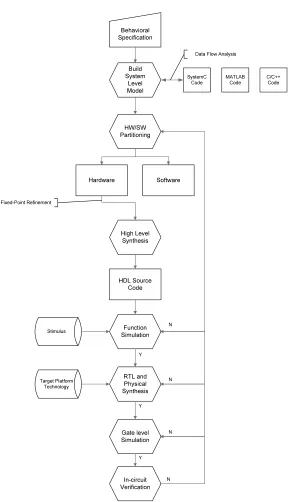
Algorithm developers analyze and verify the overall system by building system-level models using high-level languages such as SystemC, MATLAB and C/C++ codes [8, 9]. Designers use estimated performance metrics to partition the algorithm into Hardware/Software (HW/SW) to ensure the design meets the system behavioral specification. The part of the partitioned algorithm in hardware is then refined and translated incrementally into register transfer level descriptions by a high level synthesizers (HLS) or by manual efforts [10]. During this pro-cess, designers must manually refine the hardware with minimal help from synthesis tools [11]. Typically, these refinement loops are guided by performance estimation tools for hardware. Currently, this is accomplished by a designer’s intervention using designers’ insights rather than through the use of an executable abstract model of hardware performance. This insight driven approach is often valid for designing current DSP systems since the hardware’s detailed models are not available in early stages of the design. Therefore, designers who implement the flow in Figure 1.1 are challenged to complete the process in a very short design time without the help of correct early stage performance estimation data.
Behavioral Specification Hardware Stimulus Build System Level Model SystemC Code MATLAB Code C/C++ Code Data Flow Analysis
HW/SW Partitioning Software High Level Synthesis Fixed-Point Refinement HDL Source Code Function Simulation RTL and Physical Synthesis Gate level Simulation In-circuit Verification Target Platform Technology N Y Y Y N N N
Figure 1.1: Hardware Design Flow
1.1
Overview
Pro-grammable Gate Arrays (FPGAs), and Application Specific Integrated Circuits (ASICs) as in the Figure 1.2. A GPP provides full flexibility in exchange for three orders of magnitude of performance inefficiency compared to the ASIC-based implementation scheme [15]. DSPs are specialized processors optimized for domain specific DSP algorithms. A DSP can assist a GPP host processor in a designated platform and is called upon for demanding real-time specific tasks. This is the major difference between DSP and GPP. High level language support is available for DSPs. However, assembly-level language is generally used to achieve the best performance.
A FPGA enhances the flexibility of hardware beyond an ASIC by providing a design-time mapping strategy. FPGAs are used frequently instead of dedicated ASIC’s platforms. Addi-tionally, FPGAs become popular due to recent process technology advances for FPGAs and the development of mature CAD tools for FPGA based system design [16–18]. Non-Recurring Engineering (NRE) costs for ASIC design have become more expensive. Very few applications have been successful enough to justify NRE costs of an ASIC. Moreover, application designers desire to perform hardware design at high levels of abstraction. As a result, the hardware for many DSP applications have been implemented through the use of FPGAs instead of ASICs.
F le xib ility E fficie n cy
(G O P S /m W )
A S IC
F P G A
D S P
G P P
Figure 1.2: Classic Hardware Design Space
floating-point. Moreover, overflow and quantization problems must be solved manually. This causes poor C code generation on fixed-point DSP processors and increases development efforts. Floating-point DSPs have increased dynamic range over fixed Floating-point. Therefore, floating-Floating-point operations are capable of greater precision and more accurate DSP operations. Floating-point DSPs try to support operations at the speed of processing fixed point operations while preventing several problems such as overflow and signal scaling. However, floating-point DSPs provide a more expensive design option in terms of cost and silicon area. This results in slower clock speeds and higher power consumption due to increased design complexity [19].
A FPGA is a reconfigurable programmable device. Commercial FPGAs have several differ-ent styles of implemdiffer-entation. Two dimensional arrays such as Xilinx FPGAs have Configurable Logic Block (CLB) tiles which are connected by a configurable interconnection of switch box wires [17]. Xilinx CLB usually contains logic resources in the form of slices and configurable interconnects, as shown in Figure 1.3. Typically, multiple inputs Look Up Table (LUT), in logic slices, implements an arbitrary logic function. Flip-flops are used to clock the combinational output of the slice. Eight slices can communicate with neighboring slices directly using local interconnects. A set of global interconnects that run horizontally and vertically between rows and columns is used for communications between non-neighboring slices [20, 21].
Configurable Logic Block (CLB)
In te rc o n n e c t S lic e S lic e Slice L U T L U T F F F F . . . .. .
Figure 1.3: Xilinx FPGA CLB and Slices
which the slices or cells in the FPGA are routed and connected determines the performance parameters such as delay, throughput and power dissipation. Additionally, each logic block implementation strategy affects parameters such as slice resource usage. However, due to the architectural similarities, it is expected that techniques for estimating performances are appli-cable to other FPGAs and not limited to certain FPGAs if they are modeled appropriately [22]. Typically, ASICs are designed using silicon compilers that can translate schematic captures and HDL descriptions into a gate-level net-list. A silicon compiler generates gate modules that are used in a net-list from a standard cell library [23]. A standard cell library consists of pre-designed, pre-tested and pre-characterized collections of primitive gates [23]. Other tools are used to place and route the net-list onto the HW fabric. The components of the net-list are placed in a matrix and the connections are routed through this matrix.
The ASIC provides the most efficient candidate solution to implement a particular DSP algorithm in hardware in terms of several different performance metrics such as throughput, latency, area and power. However, ASICs have very limited functionality once they are manu-factured. The ASIC functionality can not be customized for different applications in the field. The total design time of an ASIC is long compared to that of programmable architectures. The modification of an algorithm requires developing a new ASIC. The low cost per unit is based upon a high number of the units being manufactured. Therefore, development cost of an ASIC is very expensive although the cost per unit is quite low and very competitive. This is the results of long and costly design cycles and therefore considerable volumes must be produced to justify the overall development costs.
1.2
Motivation
Presently, DSP designs pose many challenges and obstacles to hardware designers. The hard-ware design should consume as little power as possible and be able to work hours or even days when using lightweight batteries. It should also be flexible enough to integrate multiple stan-dards and adaptive algorithms in a single device. They must be designed and verified within a shorter amount of design time in order to maintain good standing in the market despite sub-stantially increased silicon and system complexity. DSP designers are struggling to meet these grand challenges which call for innovations of both architectures and design methodologies to address those problems. More precisely, DSP system design and refinement involves many early stage trade-off decisions among different design metrics, e.g. performance, power, design costs, time-to-market, and manufacturing costs.
and silicon manufacturing costs.
ASICs are at one end of the spectrum at a very high level. ASICs are specialized to a given application. Therefore, they have the least flexibility compared with other architectures. Their lack of flexibility introduces high NRE costs, and an extended and expensive design flow. Ac-cording to the International Technology Roadmap for Semiconductors (ITRS), the NRE costs, including both design and manufacturing costs, in the deep sub-micron era, can easily amount to tens of millions of dollars [24]. This makes ASICs an option for high-volume applications only. However, due to specialization, the efficiency is highest in terms of performance and power. On the other end of the spectrum are general-purpose processors (GPP) such as Intel’s Pentium processor. A GPP implements a limited and fixed set of generic arithmetic and control operations that can be organized and sequenced to implement arbitrary computations. This level of flexibility brings high-level programming language support, zero manufacturing and low design NRE cost for the application developer, and very fast time-to-market at the expense of efficiency. GPPs are simply too inefficient to deliver high performance and low power when applications must exploit massive parallelism [25].
Our goal is to develop an early stage performance estimation method for DSP algorithms. We believe that this method will help to develop a methodology that facilitates the derivation of abstract performance models based on the abovementioned observation. Specifically, this methodology is for quantifying a DSP algorithm’s memory complexity, related timing consid-erations, and verification of the correctness of the algorithm. After deriving appropriate sets of data flow models, the methodology provides design trade-off curves allowing for designers’ to make decisions at several stages, which ultimately leads to a final design that meets specifica-tions.
1.3
Contributions of This Work
A secondary objective of this work is to extend the use of the dataflow formalism for per-formance estimation of digital signal processing systems [26]. We propose that a methodol-ogy based upon the dataflow formalism can complement the current state-of-the-art tools for early performance estimation for DSP. DSP related applications can be solved by applying the dataflow approach which is inherently parallel and has the level of abstraction necessary for performance estimation during the early stages of the design process.
Additionally, this research provides a dataflow performance estimation utility as well as built-in models, customized for digital signal processing algorithms. It is expected to improve the communication between algorithm developers and implementation architects by providing dataflow templates to expedite dataflow coding. More specifically, the validated methodology proposes the way to efficiently generate two dimensional filtering hardware based on the block data parallel architecture. This will be useful to DSP algorithm developers and HW design-ers. They can easily extend our approach to implement their DSP algorithms by reusing our predefined set of parameters and corresponding models for hardware implementation.
The proposed design methodology can benefit various classes of designers including algo-rithm developers, hardware architects, hardware designers and software programmers. More specifically, algorithm developers can use our methodology to decide on the best algorithm can-didates based on performance parameters. This will reduce the development time to explore the feasibility of hardware design options rapidly. The hardware architects can minimize the time and effort spent on exploring potential HW candidate design options. This methodology is able to show potential benefits in these decision steps by offering a centralized methodology to the community and help reduce the knowledge gap among the group of design engineers.
1.4
Organization
Chapter 2 presents a state-of-the-art literature survey regarding design environments and de-sign methodologies relevant to this work. It describes the related different dede-sign methodology environments including tools and domain specific languages which are currently used for per-formance estimation. Moreover, Chapter 2 assesses merits and demerits of the tools and design platforms and how these advantages and deficiencies are addressed in our work.
Chapter 3 introduces the Design Space Exploration (DSE) concept and the proposed design flow usage for estimating performance. The design metrics for DSE are also derived for detailed explanation. This chapter also presents modeling approaches such as Petri net and SDF other than CAL (Caltrop) data flow and definitions of terminologies used in the dissertation.
to estimate the performance parameters early in the design process, qualitatively assessing a set of design options by providing a design trade-offs curve.
Chapter 5 presents a high level algorithmic study of SAR. The goal of this high level case study is to understand an SAR processing application and to identify both design input pa-rameters and performance output papa-rameters. Additionally, this section presents the SAR performance results from high level MATLAB models.
Chapter 6 presents experimental results and compares them with conventional methods in terms of design metrics and other performance parameters. This chapter verifies this method-ology’s approach by analyzing the accuracy and performance of case studies compared to open literature’s results and FPGA synthesis results.
Chapter 2
Related Work: Early Stage
Performance Estimation
Methodology
Early performance analysis allows designers to assess the characteristics of a design in the design cycle. We surveyed these methodologies including co-design environments such as Polis, Gezel and SpecSyn. We extended our survey to commercial hardware design tools including CoWARE. Catapult-C was presented as an example of a limited DSE tool. A survey of these tools is presented in this Chapter, highlighting the main characteristics that make them attractive for early performance estimation. This chapter begins with a survey of models of computations which are used for performance analysis and estimation. In addition, design environments used by designers are shown as well as commercial tools. Lastly, this chapter also discusses relevant high level DSP optimizations found in the literature.
2.1
Models of Computations (MoC)
Models of Computation (MoC), including graphical notations, are based upon general concept which has been proven to be efficient in Digital Signal Processing (DSP) hardware design [27]. These models, such as Petri nets and data flow graphs, are very popular and acceptable to researchers and engineers. For example, we observed that DSP algorithms typically involves data stream input and output buffers and multiple operations among them. These are the examples of dataflow MoCs which can be represented by dataflow operations and their data traveling among them with their control condition.
such as tokens and firing conditions. We identified the rationale for why the dataflow language has been chosen for analytical modeling schemes in this methodology. Our research target is the development of a formal approach to estimate the performance estimation of DSP systems. We reviewed several known approaches to the modeling of systems. Special attention has been paid to those models that are appropriate for language based transformations to make it easier to extend hardware models to add capability. A variety of models have been developed and used to represent heterogeneous systems including video compression systems. A model of computation should ideally include concurrency, sequential behavior and communication methods. We briefly describe the key aspects of the models studied here and compare their most important features.
2.1.1 Petri Nets
Petri nets by their nature are good candidates for studying and analyzing the behavior of DSP models for early performance estimation. The Petri net represents interacting concurrent components and is used as a design and analysis tool for systems. A Petri net has a set of places: P, a set of transitions T, an input function I that maps transitions to places and output function O which also maps from transitions to places. Additionally, Petri nets can be represented graphically as a directed multi-graph based on net structures. The mathematical formalism which defines its structure and firing rules, has made Petri nets well-understood [28].
T 1 T ra n sitio n
T 3 T 2
p 1 p 2
P la ce
Figure 2.1: Petri nets
of a language. This restricts the use of the Petri net in hardware design environments unless we develop the Petri net language and its automata in software. Therefore, we choose not to use Petri nets as the analytical modeling language for our HW design methodology.
There are Petri net extensions to overcome the disadvantage of limited expressive power. Stoy et al., presents a modeling technique for hardware/software systems based on an Extended Timed Petri Nets (ETPN) notation [29, 30]. This Petri net representation, PURE, is founded on a parallel model with data-control notation and provides timing information. In this approach, timed Petri nets with restricted transition rules are used to represent control flow in both hardware and software. Communication between modules is modeled by pairs of I/O operations which form join points called Rendezvous. PURE provides a concurrent and asynchronous description of the control. This representation allows the designer to capture hardware and software in a consistent way, so it can be utilized during the synthesis process, but not for analytical dataflow modeling purposes.
2.1.2 Dataflow Graph
Dataflow graphs are popular for modeling DSP algorithms. Especially, data-dominated algo-rithms such as image processing require for considerable transfer of data such as images and video frames. They can be conveniently represented by a directed graph where the nodes describe computations or transformations and the arcs represent the order in which the com-putations are performed. All comcom-putations are executed only when the required operands are available in this model. Another characteristic is that operations assigned to nodes behave as functions. As a result, computations may be performed either sequentially or concurrently. Nonetheless, the conventional dataflow graph model is inadequate for representing the control conditions of video systems or other heterogeneous systems.
2.1.3 CAL (Caltrop) Dataflow
CAL was initially developed as a specification for the Ptolemy II project [33]. The CAL actor language describes algorithms with interacting actors. Each of actors has its own state and functions. Communications and interactions among actors can be processed through channels or First Input First Output (FIFO) buffers. Actors define functions described by a set of actions. Actions typically consume input tokens, generate output tokens and modify the internal states which is very similar to Petri net’s characteristics. CAL has expression capabilities sufficient to specify a wide range of video compression algorithms that follow a variety of dataflow models. CAL, as a dataflow-oriented language, was a promising answer to our analytical modeling language search. It has also been chosen by the MPEG Reconfigurable Video Coding (RVC) standardization committee as its normative language. Thereafter, researchers began using CAL to describe video compression encoders and decoders. Recently, a new standard compression algorithm named High Efficiency Video Coding (HEVC) also known as H.265 has been success-fully released using CAL language descriptions [34]. Until recently, CAL has been developed with the committee’s focus for reconfigurable modeling rather than for abstract performance estimation as used in our methodology.
CAL has strong encapsulation capability for coding tools. It is built on top of explicit descriptions of the parallelism inherent in a DSP algorithm. We were interested in this modeling capability intended for video compression algorithms. We also utilized the dataflow concept which creates the opportunity to perform a wide range of performance estimations by analyzing and implementing dataflow systems in CAL. Furthermore, CAL explicitly was designed with a number of relevant properties for dataflow actors. We use these properties for the extraction of input parameters and apply them to performance estimation simulations. Concurrency benefits system execution speed, especially for early estimation of system performance as in the case of video decoders.
RVC-CAL is a subset of the original CAL language and is being used to develop the RVC standard Video Tool Library by the IET working group. The most significant differences between CAL and RVC-CAL are that RVC-CAL supports only a subset of dataflow types. Advanced features of CAL, such as channel selectors and multi-ports, or lambda-functions are prohibited. This is because the hardware synthesis of programs written in a RVC-CAL language is easier if the language is restricted. We will be using RVC-CAL language features for analytical dataflow modeling for hardware synthesis.
concurrency as well as sequential behavior at the abstraction level with dataflow characteristics. We described the features of several representation models. Most of them are well suited for data or control-oriented systems but only one representation, CAL support, has a language based approach. The other two representations are based on strong mathematical semantics, making them easier for formal verification, but difficult for adaptation to be used as an analytic modeling language in a dataflow methodology. The characteristics of those representations can be compared using the terms of the main application; timing, clocking schemes, whether the model is synchronous or asynchronous, communication method, hierarchy, non-determinism, and mathematical formalism or programming language support.
2.2
Performance Estimation Methodology and Tools
This section presents and discusses state-of-the-art research which is relevant to performance estimation methodologies. Most important relevant research falls in the categories of Hard-ware/Software (HW/SW) co-design, and compiler/profiler directed approaches.
2.2.1 Hardware/Software Co-design Approaches
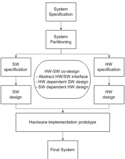
Historically, a great deal of research effort has been expended toward HW/SW co-design ap-proaches. The traditional application specific integrated circuit ASIC designer has a hardware centric view of system design. Software designers have a software centric view point. However, today’s system requires the need for application specific design because of high performance needs at the boundaries of hardware and software. Compared to general system design prac-tices, designers must consider both hardware and software which are tightly coupled. Although designers use the HW/SW interface model to bridge the gap between hardware and software, this also leads to problems due to separate models of hardware and software. This results in more design time overhead and reduced efficiency.
Figure 2.2: General HW/SW Co-design Flow
• Unified design representation based on behavioral specifications able to describe system hierarchy and abstract HW/SW interface at different levels.
• Software mapping tool which targets high level software models on specific processor platforms.
• Interface generator which adapts to hardware/hardware or hardware/software with dif-ferent interface and protocol/communication structures.
• Co-simulator which allows for producing executable model for heterogeneous systems.
Polis
The Polis project of Berkeley was one of the first HW/SW co-design tool projects that focused on homogeneous behavioral representation to model hardware and software [2]. The behav-ioral representation uses a CFSM (Co-design FSM) as a model of computation. Additionally, Ptolemy is used as a co-simulator to validate the functionality of the system without detailed implementation.
mapping behavioral functions in CFSM to architectural resources. The computation intensive kernel that causes the energy and performance bottleneck needs to be identified. HW/SW partitioning, scheduling and communication refinement is completed manually to explore design space of the design in this step. Therefore, designers make all of these decisions based on their insights to co-simulate the heterogeneously CFSM-modeled system. CFSMs is divided into hw-CFSMs and sw-CFSMs. The partitioned hw-CFSMs can be synthesized by the automatic synthesis tool in Polis. Moreover, automatic synthesis of hardware and interfaces allow the designer to implement a variety of algorithms with fast design cycles.
The methodology in the Polis approach is useful to model and co-simulate an embedded system and therefore can be optimized easily for the given behavioral specifications in CFSM by designers. However, the designer must build a system design collectively and exhaustively to estimate the performance. This adds to the complexity of building a complete model for early performance estimation which makes this approach difficult to use in Design Space Exploration (DSE) of DSP hardware.
Graphical FSM
Esterel, ECL
CFSMs Compilers
Intfc + RTOS Synthesis
Logic Netlist
HW synthesis
Architectural Description
SW synthesis
SW Code + RTOS Simulation
Partioning Formal Verification
Rapid Proto. Implementation
Gezel
Gezel is a domain specific HW/SW co-design tool for cryptography application and educational purposes [36]. Cryptographic applications require certain parts of applications to be in secure hardware circuits. Additionally, arithmetic intensive kernels have to be mapped onto hard-ware. This design style and verification of security application protocols results in Gezel design environments. Gezel supports modeling and design of hardware components by providing the proprietary Gezel language called Finite State Machine with Data Path (FSMD) [37]. The complete Gezel Platform comes with Gezel kernels and other simulators including Instruction Set Simulator (ISS).
Gezel uses an FSMD network which offers ways to extend the basic instruction set of the processor in order to accelerate specific kernels. In this approach, Gezel provides a template processor and its basic instruction set and uses FSMD language to generate functional units for user defined extension. The program’s dataflow graphs can be mapped onto a new cus-tom functions unit which will achieve high performance gains including fewer cycles and low fetch/decode overhead. The advantages of this approach are the reduction of the code size and lower power consumption. However, this design environment provides limited sets of hardware platforms with designated processors highly specialized for cryptographic algorithms.
SpecSyn: SER (Specify-Explore-Refine)
SpecSyn is based on the complete SpecC based co-design environment for general purpose hard-ware design [38]. Initially, it was intended to handle increasing cost and design complexity in the hardware design by proposing the Electronic System Level (ESL) language. Among HW/SW co-design tools, SpecSyn has a focus on C-to-RTL high-level synthesis which models hardware and software without boundaries in initial design although SpecSyn requires manual component assembly. Specify-Explore-Refine (SER) is a methodology in SpecSyn which generates platform design models at different levels of abstraction [39]. A system platform can be developed in a step-by-step manner gradually by using the SER environment. SER design flow describes system behavior in SpecC (Specify). This is followed by a design step that explores the design space through scripting in an SER environment (Explore). This step generates refined mod-els at a lower step of abstraction (Refine). This design space exploration includes HW/SW partitioning, network topology design, bus protocol selection and bus interface synthesis.
a next step exploration. Network exploration is performed on the topology and connectivity, then designers define routings and channels. Refinement is the merging and rebuilding of architectural models of channel to point-to-point links among processing elements.
The designer still needs to describe quantitative estimation metrics and run entire design cycles using simulations although SpecSyn and SER methodology provide extensive sets of tools to model and refine algorithm from SpecC. As a result, system level languages such as SpecC provided hardware designers options to accelerate modeling and design process. However, designers are still unable to shorten the performance estimation cycle time due to its long run-time.
CoWare
CoWare is a HW/SW co-design environment based on OCAPI/C++ developed at Inter-University MicroEletronic Center (IMEC) [40]. CoWare tools are based on SystemC System-on-a-chip plat-forms which can create and modify a platform at the ESL level [41]. The platform architecture captures design at high levels of abstraction using devices such as processors, busses, custom IP blocks, and peripherals. The benefit of using the CoWARE tool is that the bus based system can be constructed in a few hours by selecting pre-built components. Additionally, Coware pro-vides integrated modeling, simulation and a debugging environment for complex on-chip bus based networked systems as well as transactional system busses such as AMBA, OCP-IP and AXI. This enables designers to debug and analyze a hardware platform by following TLM pro-tocols. Debugging and profiling capability will provide cycle accurate performance parameters and identify bottlenecks of applications.
CoWARE is a more evolved design environment than SpecSyn since it provides predefined performance metrics and tools which can be used readily for performance estimation. However, CoWARE tools focus only on the performance estimation for bus based systems and on-chip networked systems. The tool does not provide performance parameters beyond bus performance parameters for general performance estimation.
2.2.2 Function level Design Exploration Tool : Catapult-C
an un-timed ANSI C/C++ code describing an algorithm in restricted grammar. The subset of ANSI C/C++ code is intended to drive Catapult-C behavioral synthesis. Like other behavioral synthesis tools, there are several limitations in that pointer usage is restricted and recursion is not allowed in Catapult-C code. After inserting Catapult-C preprocessor directives to establish structural constraints, architectural constraints are determined by designers. Loop unrolling, pipelining and data pre-fetching are major optimization options available in this step.
Set Architectural and Resource
Constraints Untimed C/C++
Algorithm
Schedule
Generate RTL code Constraints
met ? A set of
FPGA/ASIC libraries
Automatic refinement Loop constraints
optimization
Figure 2.4: Catapult-C Design Flow [3]
A statically scheduled Gantt chart is displayed for visual analysis and as an aid to verify design parameter changes. In this step, designers would be able to intervene and explore design space of specific functional units although changes are restricted to bit width and loop constraints. Hardware RTL in Verilog and VHDL is synthesized after a schedule step. Finally, static timing analysis is performed to estimate latency and throughput.
After all of these steps, C++ simulation results can be compared to RTL simulation results. Furthermore, Catapult-C automates system verification and validation tasks. Verification such as C code execution vs. RTL simulation matching is automatically performed at an un-timed functional level. Other tools are also integrated into the Catapult-C design environment to give designers ease of design space exploration using Power analysis and SystemC transaction level simulation. The hardware mapping target is composed of FPGA and ASIC libraries.
implemen-tation. Catapult-C directives carry low level optimization contexts such as defining the initial-ization interval in pipelining stages. Although this should be precisely inferred in Catapult-C code, Catapult-C can utilize the specific directives to synthesize with a corresponding type of hardware. This has the drawback that the DSE scope is very narrow and can therefore only be utilized in rare circumstances. However, this minimizes potential human design errors which are typical in this step of data path design. Hence, Catapult-C is beneficial to implement a functional unit with an automated optimization support. It has a limitation for an performance estimation at early stage.
2.2.3 Compiler Directed Approaches
Most compiler-directed approaches focus on performance estimation issues for general pur-pose processors based on compiler optimization. The group at IMEC takes a pre-compiler approach where memory model parameters are captured [40, 42]. This methodology consists of a platform-independent exploration step and a memory platform-dependent step. The first step is independent of target architecture and the output source code can be used regardless of the target implementation. This includes source code transformations which result in opti-mal points where memory related energy and data access cycles are traded off. This includes cost estimators of memory related optimization steps. However, the performance estimation is limited to a set of memory parameters and can only be applied to specific optimization such as local and temporal variable optimization. Additionally, a model and corresponding formal method to optimize the required memory bandwidth should be developed. Only the prototype tool support is available for a set of of source code level transformation steps.
2.2.4 Other Adhoc Approaches
In addition to these approaches, various ad hoc methods and approaches for estimating perfor-mance early in a design and optimizing memory subsystems exist.
Compared to compiler based optimization approaches, many memory subsystem architec-tures were proposed for typical SoC. These memory architecarchitec-tures deal with memory design issues in specific SoC domains [42]. Multi-level memory hierarchy is a popular implementation scheme for meeting huge memory bandwidth requirements. Cache memory is not required for embedded systems because power consumption is more important than memory bandwidth. The most typical implementation makes use of on-chip memory (scratch pad memory). This is similar to cache memory but it differs in that it does not require dedicated custom logic to fill memory contents. This is especially popular when the designer has full control of software and hardware. Most of the memory hierarchy abstraction level is at the RTL hardware level. Therefore, it is difficult to re-target designs developed using this approach and results in limited design space exploration (DSE) freedom.
The PAF is an elaborate project by Ramsey Hourani [46]. The contribution of PAF is that it efficiently generates and synthesizes hardware models for basic DSP algorithms. Additionally, PAF is able to analyze the performance of different hardware representations and provides a method to quantify the performance quality of generated design in terms of area, power and throughput. The main goal of this work is to bridge the gap between DSP algorithm designers and hardware designers.
2.3
Dataflow Concepts and Block Data Parallel Architectures
guidance. We chose dataflow representation for the following reasons:
◦ Dataflow is an efficient and proven tool for certain categories of high performance DSP im-plementations. Many DSP algorithms repeatedly apply the same fixed order of operations for streaming data. Additionally, dataflow is effective for the description of algorithms in finite and coarse detail.
◦ Dataflow handles optimization schemes as easily as insightful designers do.
◦ Timing issues due to clock skew and clock distribution can be avoided by adopting an asynchronous mode such as Globally Asynchronous Locally Synchronous (GALS), in-herent in dataflow model and performance estimation. GALS is a concept based on a distributed implementation style [47]. GALS is compliant with a dataflow concept such that individual blocks are implemented based on a synchronous clocking scheme. The interacting blocks exchange the information asynchronously through tokens using FIFOs. The synchronization issues are easily addressed in dataflow based modeling and simula-tion.
◦ Dataflow is one way to reduce design time significantly, especially if a pre-built design methodology such as the one we adopted. We maximized the benefits of our methodology with the help of many public and commercial tool chains e.g., the FPGA synthesis tool. Our method can help designers make design choices early based on quantified performance estimates generated by our tools.
We can maximize the performance of the implemented hardware blocks by providing a GALS oriented block dataflow concept. It has given rise to an alternative approach to super-scalar designs for scalable, low-complexity, and high performance processors with a distributed architecture and execution model. We use GALS, in many cases of DSP, to maximize the throughput by localizing data traffic residing in a narrow boundary of block processors. We also minimize the global data transfer by limiting it to the exchange of state space variables achieving a minimal impact in terms of increased global signal and data transfer.
the time required to feed the data into the PE. This concept has been conceived and validated for several different multi-dimensional filtering applications in the literature [49].
The hierarchical dataflow is bounded within the block so that individual processing elements operate simultaneously in an asynchronous manner. This is very much in line with accepted dataflow concepts and is compliant with the key optimization methods for the exploration of design space. The intermediate results among blocks are transferred using point-to-point interfaces, allowing BDPA to run faster and allowing the designers to apply different clocking schemes.
f(n1, n2)
Computations
Z1-1
g(n1, n2)
QV(n1, n2-1) QV(n1, n2)
QH(n1-1, n2) QH(n1, n2)
Figure 2.5: Modified Finite State Machine of Block Data Parallel Architecture (BDPA) [4]
Regarding the simulation of dataflow cycles, we also used a native simulation for greater speed and more efficient use of memory. BDPASIM is a native simulator developed in C [4]. CAL simulation has, for our purposes, a few limitations. RVC-CAL was mainly developed for a small block based video compression in Eclipse environments [50]. Relatively large blocks size such as 4k×4kmake it difficult to simulate the entire dataflow description in the environment. We bypassed the Eclipse environment and implemented interface libraries in C/C++ codes to resolve some problems. However, we found that these might limit our throughput estimation. We used BDPASIM for the dataflow simulation with large image size blocks.
data flows through the FIFO to the output device after the OM. In this paradigm there is no need to store data or intermediate output results in the BDPA architecture. The BDPA can be used to implement most DSP algorithms. The Finite Impulse Response (FIR), Infinite Impulse Response (IIR) and Discrete Cosine Transform (DCT) operations have been implemented using BDPA architecture [49].
Beyond architecture modeling, we also implemented dataflow transmission protocols among processor units. The detailed protocol is presented [4]. This protocol is based on a GALS clocking scheme that minimizes the clock skew problem and also reduces asynchronous hand-shaking overhead since it is implemented on local synchronous protocols. The IM and the OM have multiple FIFOs which are used to feed blocks of data to the PMA. The PMA has multiple PMs which are connected via local asynchronous channel. This local data exchange or some other state variable exchange is the only necessary communication overhead requirement. This enables the BDPA achieve linear speed-up execution on multiple processor implementations.
We use this modified FSM to reconstruct the filtering algorithms as in the literature present-ing block recursive equations. In this block recursive structure, 2D product-separable filterpresent-ing can be decomposed to line by line processing which makes it easier for HW implementations. By keeping the intermediate values in temporary buffers, we can reconstruct the 2D filtering al-gorithms to single level filterings with local buffers. The data access scheme is simpler and data storage is reduced. The interchange of information is also reduced by retaining minimal data. The modified FSM that presents the vertical state vectors interchange was replaced by proper state vector composition. We referred to the representative literature to build our dataflow recursive concept. We specifically use BDPA’s approach and mathematical formulations. Our derivation is fully presented in Chapter 4 of this dissertation.
2.4
Definitions and Terminologies
This section provides definitions of terminology discussed in the dissertation.
• Abstraction: Reduced description of a system using modeling by which detailed imple-mentation is hidden at a specific level.
• Actor: An entity for a dataflow unit with input and output stream ports. An actor’s computation is activated by tokens produced by other actors and it’s output tokens are produced as a result of a computation.
• Pareto-(optimal) Curve: A Pareto curve is a multi-axis plane used to characterize op-timized mappings of a given algorithm. The axes of Pareto curves are typically constraint axes, resource axes, platform parameters, and cost axes.
• Design Space Exploration (DSE): The process of finding the group of hardware candidates that best fit the requirements. The cost function of this process is defined by design input and output parameters. In general, this is pursued on a Pareto-optimal curve points set.
• Map: The uni-directional relationship between an algorithm and the elements of the architecture it defines.
• Model: A kind of representation of a function and behavior of a system by abstraction so that an adequate degree of accuracy in performance values can be extracted at a certain level.
• Performance: A quantitative measure for certain aspects of systems parameters char-acterizing systems’ behavior.
• Platform based design: A reuse driven abstract model design methodology in which components of design are pre-designed and pre-verified for integration.
• Partitioning: The process of dividing an algorithmic specification into multiple concur-rent processes by utilizing inheconcur-rent parallelism with assumptions that these processes will be assigned resources such as processors, communication, storage and hardware blocks. • Refine: A derivative implementation in hardware is said to be refined if the derivative
has behaviors that an initial requirement does not have. Additionally, abstraction of derivative specification should be described in a language description in detail.
• Simulation Accuracy: The comparison of the results’ certainty indicated by the model with the actual performance of the hardware.
• Specification Requirement: The condition or capability required by users to solve a problem; a condition or capability which must be met by a system to satisfy standards or other formally imposed requirements.
2.5
Chapter Summary
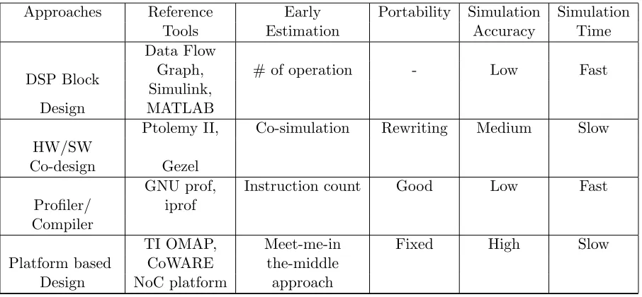
Hardware/software co-design and compiler groups’ focus has been directed toward esti-mating the early performance of applications. HW/SW co-design tools such as Ptolemy II, Polis and Gezel lead to effective design environments which can be used to co-simulate and/or co-synthesize heterogeneous systems and techniques for optimizing and reducing memory re-quirements. However, these tools rely on dynamic simulation with incremental refinement. They focus on more accurate memory metrics with the latest possible algorithm-architecture binding.
Compiler directed tools which use instruction level complexity such as software profilers exist. The basic idea of these tools is that applications spend a large share of execution time in a kernel or inner loop. As a result, they are mainly focused on instruction level complexity in a program rather than on a potential measure for the final implementation of a system in terms of memory complexity or other performance considerations. Therefore, designers are hesitant to utilize these tools to assess algorithm candidates or to provide architecture candidates for the application. Additionally, the estimations produced by the compiler and profiler approaches depend on a specific general purpose process or platform, lacking representative metrics for custom hardware or hardware/software systems design.
Table 2.1: Survey of Approaches
Approaches Reference Early Portability Simulation Simulation
Tools Estimation Accuracy Time
DSP Block
Data Flow
Graph, # of operation - Low Fast
Simulink,
Design MATLAB
HW/SW
Ptolemy II, Co-simulation Rewriting Medium Slow
Co-design Gezel
Profiler/
GNU prof, Instruction count Good Low Fast iprof
Compiler
Platform based
TI OMAP, Meet-me-in Fixed High Slow
CoWARE the-middle Design NoC platform approach
Chapter 3
Dataflow Based HW Design
Methodology
We surveyed the work related to early performance estimation method in the previous chapter. The dataflow concept has been used by hardware designers to implement DSP algorithms efficiently whether they used the Petri nets or graphical dataflow notations. Many high level DSP optimizations can be applied to hardware designs with the help of dataflow transformations such as pipelining, folding, unfolding and block data parallel access schemes as covered in Chapter 2. Generally, dataflow is an effective starting point for hardware designers who design DSP hardware systems. Additionally, dataflow concepts can lead to an efficient algorithm implementation in a short development time. We focused on the dataflow concept and and the use of the related approach to build a HW performance estimation platform in this chapter.
The objective of this dataflow based HW design methodology was to generate, estimate and analyze the performance for DSP algorithms efficiently in the early stages of HW design. This HW design and refinement methodology provided a dataflow formalism with dataflow modeling support and a set of pre-built dataflow template libraries. HW designers and algorithm developers can construct early dataflow models for quick assessment which allows them to quantify the hardware performance values. The dataflow modeling using a dataflow language, such as CAL, can help algorithm developers and hardware designers explore and reduce the hardware design space to efficiently meet requirements for given design constraints [26]. We developed a dataflow based methodology for designing and analyzing data intensive hardware designs specifically for FPGA platforms. The methodology here introduced could be applied to other algorithms such as control algorithms and other DSP data streaming algorithms.
construct-ing dataflow models for hardware performance estimation steps. We also describe classical transformations such as folding, unfolding and pipelining which allowed designers to consider alternative efficient hardware implementation candidates.
3.1
Early Stage Performance Estimation Methodology
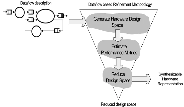
Generate Hardware Design Space
Reduced design space Dataflow based Refinement Methodology
Reduce Design Space
Estimate Performance Metrics
Synthesizable Hardware Representation Dataflow description
Figure 3.1: Concept of Our Dataflow Performance Estimation Methodology
Figure 3.1 presents a high-level conceptual overview of our dataflow based refinement methodology which refines a DSP algorithm to synthesizable hardware. This methodology begins with a potentially large design space at the top. Then, the methodology involves the use of performance estimation and the associated metrics as a basis to reduce the design space. These decision steps present the designer with a design space with cost-performance trade-offs. This does not affect the functional behavior of the design but represents the different sets of design spaces in a Pareto-optimal curve [51]. HW designers would spend less effort and design time for the overall hardware design by reducing the design space early on, based on reasonably accurate performance estimation results.
such as timing delay and power can be estimated using a dataflow simulation. Additionally, Pareto-curve can provide hardware trade-off information to be used to choose a candidate hardware architecture with assurance [51–54]. This provides a clear advantage over relevant tools and other methodologies which do not provide this capability during the early stages of the design.
The goal of this research is to develop a dataflow based refinement methodology which designers can use to easily and quickly assess the hardware performance as they change design parameters. Generally, there are multiple ways to build DSP systems on platforms including programmable processors, ASICs and FPGAs. Often, it was desirable to display the alternative design choices visually in multiple axes or to use Pareto-curves for cost-performance trade-off comparisons [51].
We have described each of our methodology’s steps in the following section. We use a dataflow description to model our algorithm. Our methodology involves the estimating perfor-mance parameters based on dataflow modeling and simulation of algorithms. This approach provides the capability to reduce the HW design space by providing designers with a set of DSE trade-off to guide hardware designers in the selection of efficient architectures based on resource utilization, throughput, latency and power dissipation.
3.1.1 Dataflow Modeling Step
A DSP system can typically be described with the use of a block diagram connected by inherent dataflow. The fundamental block in the form of an actor or function performs its operations i.e. firing when operands become available at its inputs [26]. The overall system control results from supplying operands to the actors or functions. The complexity of the actors depends upon the granularity of the DSP sub-systems, whether fine or coarse grain dataflow. The dataflow model is a scalable and low-complexity model as compared to centralized processing and modeling since it asynchronously operates based on the availability of operands. Thus, the dataflow model is an efficient and simple model that can be used for early stage performance estimation. We focused on the dataflow model because it is easy to change at the early stages and the changes impact the architecture for the resulting HW design. This fact that the high level DSP transformations affect the final system’s performance values within DSP systems supports this assertion. Generally, Design Space Exploration (DSE) at a low-level of abstraction results in limited opportunity for optimization of the hardware [39].
con-cepts can be applied to other platforms including Multi-Processor System-on-a-Chip (MpSoC), General-Purpose Graphics Processing Unit (GPGPU) and FPGA platforms. Those high level transformations can lead to more efficient execution even for irregular architectures including reconfigurable architectures. This is true because high level transformation are well suited for custom dedicated Functional Units (FU) and their associated memories as well as for efficient data addressing schemes.
Producer Actor
for int k in 0 .. 99 … . Producer_action()
… .
Consum er Actor FIFO
1 99 1 1
Action description
Figure 3.2: A Simple Dataflow Example
The dataflow concept involves the use of actors that map input tokens to output tokens when they fire, which is equivalent to the generation of producing outputs [55]. The actor fires repeatedly upon receiving its input tokens or data streams. The static dataflow model was introduced by Dennis [56]. The commonly called ”graphical dataflow programming” was introduced by Edward A. Lee and Ptolemy project [55, 57, 58]. A simple data flow model is presented in Figure 3.2. Each actor node can fire if all operands are available and execution conditions have been met. There should be data available at the consumption rate for efficient operation. Sample rates have been designated at the production rate in Figure 3.2. The text box describes the interacting behavior of the actors in pseudo code. Each actor had its own state and functions. Communications and interactions among actors are processed through First Input First Output (FIFO) buffers. Internally, the actions consume input tokens, generate output tokens and modify their internal state which results in the execution of the algorithm. The data stream has to be guided via actors and actions to the desired output port.
estimations. Performance can be estimated through the use of designer-defined metrics which are the means of quantification used to evaluate the performance of designated algorithms. Those metrics include performance parameters such as throughput, latency, area, visual qual-ity; memory parameters such as peak memory bandwidth, number of memory accesses; and dataflow parameters such as number of actors, number of produced actions and communication parameters.
3.1.2 Estimating Performance Step
Hardware designers can refine each level of the abstracted design into the next level by using synthesis CAD tools or manual efforts based on qualitative metrics. Those performance metrics including classical performance metrics such area, delay, and throughput are difficult to estimate from a high level abstraction of a given algorithm. We categorized several classical performance parameters which are used to quantify the computational complexity and the new dataflow metrics as well.
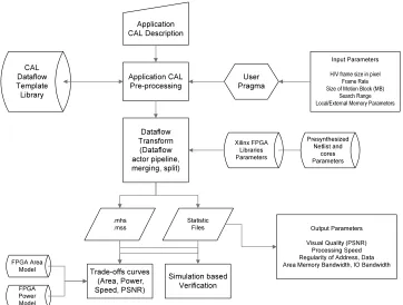
Application CAL Description Application CAL Pre-processing User Pragma Input Parameters
H/V frame size in pixel Frame Rate Size of Motion Block (MB)
Search Range Local/External Memory Parameters
Dataflow Transform (Dataflow actor pipeline, merging, split) Xilinx FPGA Libraries Parameters Presynthesized Netlist and cores Parameters CAL Dataflow Template Library .mhs .mss Statistic Files Trade-offs curves (Area, Power, Speed, PSNR) Simulation based Verification Output Parameters
Visual Quality (PSNR) Processing Speed Regularity of Address, Data Area Memory Bandwidth, IO Bandwidth FPGA Area
Model
FPGA Power Model
Figure 3.3: A Design Methodology for estimating performance of DSP algorithms
esti-mate performance metrics for refining DSP algorithms in order to select appropriate HW archi-tectures. Presently, this methodology was developed to focus on streaming applications such as image processing including Synthetic Aperture Radar (SAR) and video compression algorithms. We used a pre-built dataflow template library approach which enabled the rapid building of high-level dataflow models as compared to conventional HW/SW co-design approaches. Our methodology begins with a dataflow description as presented earlier in this section. We selected the Caltrop language (CAL) as a starting point for describing a candidate algorithm using the dataflow concept. CAL is an efficient candidate for studying and analyzing the behavior of dataflow models for performance estimation [26]. Additionally, CAL has been adopted as a standard language in the video compression community and its use should help make the use of our methodology more acceptable to designers. Additionally, we determined that CAL had efficient modeling capability since it comes with a language property and automated design tool sets including a CAL language parser and its high level synthesis tool.
The dataflow description requires input parameters such as maximum width of the frame size in macro-blocks, the size in bits of the macro-block, and the horizontal and vertical search ranges in pixels for the DSP algorithm. We generated the extended CAL model in an automated manner using our methodology by combining a set of dataflow templates such as parameterized motion estimation sub-blocks. We reused CAL dataflow templates for different DSP algorithms which provides the capability for designers to easily build dataflow descriptions. Trade-off curves with Design Space Exploration (DSE) statistical files are generated so that designers can assess the performance of different algorithms during the early stages of design.
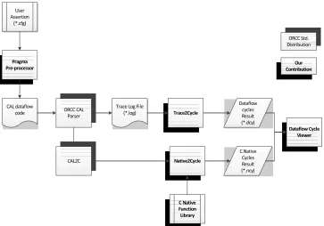
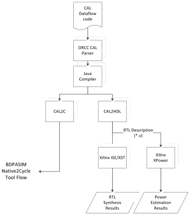
Figure 3.4 illustrated the high level performance estimation tool flow for our design method-ology. We used a CAL parser and other tool sets such as CAL2C and CAL2HDL from the ORCC standard distribution [26]. We simulated dataflow codes to validate the functionality of HW designs and to perform the performance estimation to obtain dataflow execution parameters such as token firings, and dataflow operation counts. These codes then were translated to C and HDL descriptions. We then mapped the HDL descriptions onto a FPGA detailed simulation and emulation on real FPGA devices.
Dataflow cycle is defined as the number of token firing among specified actors when all incoming tokens were produced and consumed along the specified actors’ paths. The cycle counts can be measured from the start to finish of the whole process using data tokens. The dataflow cycle count reflects the real dataflow simulation performance because it accounts for latency, data bottlenecks and overall throughput.
CAL dataflow code User Assertion (*.cfg) ORCC CAL Parser
Trace Log File
(*.log) Trace2Cycle Dataflow cycles Result (*.dcy) CAL2C Native2Cycle C Native Cycles Result (*.ncy) C Native Function Library Dataflow Cycle Viewer Pragma
Pre-processor ContributionOur
ORCC Std. Distribution
Figure 3.4: Our Dataflow Cycle Estimation Flow Overview
cycles statically, as assigned at design time. First, we generated the dataflow CAL codes by instrumenting user assertions based on designer’s description file (*.CFG). Our pragma utility specified which actors or series of actors would be executed and identified the dataflow cycles boundary. Trace2Cycleused the specified algorithms to detect and measure dataflow cycles. Due to the nature of dataflow simulation, it was possible to measure this dataflow cycle by sort-ing it out ussort-ing our algorithm. Secondly, Native2Cyclecan be used to measure instructions based time consumption as we provided Native2Cycles library routines. CAL2C generated C codes from CAL dataflow codes and executed them on a dedicated processor such as PC so that the HW designer can check C cycles.
3.1.3 Design Space Reduction Step using Pareto Curves
We used our methodology to represent the HW design space by estimating a set of performance parameters. Designers can evaluate with cost vs. performance trade-offs in the form of Pareto curves. The HW design space can be generated with the help of high level dataflow transforma-tion, such as pipelining, block data parallel schemes and other dataflow level transformations.
spaces of interest. Formally, Pareto curves were generated by locating the performance parame-ters for multiple HW candidates in a multidimensional design space. The Pareto sets offeasible
or admissible Pareto points for configuration vectors c with respect to index n are computed. Pareto pointDn of configurations of n is defined as followings [51–54]:
Dn={d= (n, c)|c f easible} (3.1)
Designers can compare different design candidates effectively with the help of objective functions based upon Pareto curves. This can usually be done visually for dual criteria trade-off curves or by using a multi-objective optimization as shown in Figure 3.5.
P
e
rf
o
rm
a
n
c
e
Cr
it
e
ri
a
#
1
D
1Performance Criteria #2
D
2D
3Figure 3.5: Examples of Pareto curves.
3.1.4 Synthesizing HW/SW from Dataflow
The dataflow model has concise expression capabilities that designers can effectively translate into HW and SW. The dataflow program was simulated on the Java Virtual Machine (JVM) interpreter which executed a network of actors as shown in Figure 3.6. The connections for the actors were specified by the Function Network Language (FNL) in CAL dataflow. Additionally, the dataflow simulation could be performed via a interpreter based or a compilation based method. Both are supported by OpenDF tool-sets beyond CAL dataflow parsing.
CAL Dataflow
code
ORCC CAL Parser
RTL Synthesis
Results Java
Compiler
CAL2C CAL2HDL
Xilinx ISE/XST Xilinx
XPower
Power Estimation
Results RTL Description
(*.v)
BDPASIM Native2Cycle
Tool Flow BDPASIM Native2Cycle
Tool Flow
![Figure 2.3:HW/SW co-design tool chain in Polis [2]](https://thumb-us.123doks.com/thumbv2/123dok_us/1319047.1164686/27.612.171.461.324.635/figure-hw-sw-co-design-tool-chain-polis.webp)
![Figure 2.4:Catapult-C Design Flow [3]](https://thumb-us.123doks.com/thumbv2/123dok_us/1319047.1164686/30.612.170.459.193.421/figure-catapult-c-design-flow.webp)