70:2 (2014) 33–39 | www.jurnalteknologi.utm.my | eISSN 2180–3722 |
Full paper
Jurnal
Teknologi
Effect of Sintering Aid on CGO Electrolyte for the Fabrication of Low Cost,
Structural-controlled Solid Oxide Fuel Cell
Krishnan Manakora, Siti Munira Jamilb, Mohd Hafiz Dzarfan Othmanb*, Mukhlis A. Rahmanb, Juhana Jaafarb, Ahmad Fauzi Ismailb
aFaculty of Petroleum & Renewable Energy Engineering, Universiti Teknologi Malaysia, 81310 UTM Johor Bahru, Johor, Malaysia bAdvanced Membrane Technology Research Centre, Universiti Teknologi Malaysia, 81310 UTM Johor Bahru, Johor, Malaysia
*Corresponding author: [email protected]
Article history
Received :1 November 2013 Received in revised form : 1 June 2014
Accepted :30 June 2014
Graphical abstract
Abstract
This paper reports the effort in reducing sintering temperature of cerium gadolinium oxide (CGO), a common intermediate temperature solid oxide fuel cell (SOFC) electrolyte, by doping it with lithium
nitrate (LiNO3) at 1, 2 and 3 mol%. LiNO3-CGO/NiO-CGO electrolyte/anode dual-layer hollow fibre
(HF) for micro-tubular SOFC has been developed in this study via brush painting technique. The developed dual-layer HFs, which are co-sintered at 900-1250°C with the interval of 50°C, characterized by mechanical strength and microstructural analysis. Benefit of this study is the reduction of the sintering temperature, which eventually contributes to the fabrication of low-cost SOFC. Moreover, brush painting technique provides great adhesion between anode and electrolyte layer during sintering. With the
increasing sintering temperature and content of LiNO3, densification and the mechanical strength of the
developed dual-layer HF increased. Based on the experimental works, a sintering temperature of 1150°C
with 3 mol% of LiNO3 as sintering additive is recommended for the construction of the low cost
dual-layer micro-tubular SOFCs.
Keywords: Cerium-gadolinium oxide (CGO); lithium nitrate (LiNO3); sintering aid, micro-tubular solid oxide fuel cell (MT-SOFC); sintering temperature
© 2014 Penerbit UTM Press. All rights reserved.
1.0 INTRODUCTION
Fuel cell has drawn attention of many people in past few years. This technology has been regarded as an alternative to resolve the depletion of the natural resource, global warming and green house effects. Fuel cell is a device which converts chemical energy from fuel to electrical energy through chemical reaction [1]. Fuel cell generally consists of three main components namely cathode, anode and electrolyte. Cathode is the positive side meanwhile anode is negative side. Electrolyte is the medium that allows the movement of the charges between both sides. Electrolyte can also be considered as a catalyst since it speeds up the reaction between the two electrodes. In general, the fuel discharges electron at anode and becomes positive. Electrolyte is designed in such way in order to allow only ions to pass through but not the electrons. The electron travels through the wires which eventually creates electric current flow [2]. Ions travel through the electrolyte and reach the cathode where it reacts with electron and another chemical, normally oxygen to produce water. However, solid oxide fuel cell (SOFC) operates in the different manner where reduction of oxygen occurs at cathode. These ions
later diffuse through the electrolyte and electrochemically oxidise the fuel at anode [3]. Among all types of fuel cell, SOFC has attracted great interest as it possesses so many significant advantages compared to other types of fuel cell. Some of the advantages of SOFC are greater tolerance to thermal cycling, quicker start up capability, higher volumetric output density and
many more, [4-5].
Of the many materials with the potential to be used as a SOFC electrolyte at intermediate temperature, cerium-gadolinium oxide (CGO) has one of the highest ionic and higher thermal expansion coefficient which is more compatible with anode metallic components and cathode materials [6]. However, it is still difficult for CGO to be densely sintered below 1500°C by the conventional method. High sintering temperature of electrolyte results in several disadvantages such as high manufacturing cost,
reduction of Ce4+ to Ce3+ and undesired electrode structure [6].
Two measures are usually taken in order to reach complete densification. First, the initial particle size of the powder is reduced to the nano meter range, thus increasing the driving force for sintering [7]. Second, small amounts of sintering aids such as transition metal oxides are added to increase the sintering rates. Kleinlogel and Gauckler reported the sintering of Ce0.8Gd0.2O1.9 at temperatures as low as 900°C using transition metal (Ni, Cu, Co) oxide additives [5]. Work at Imperial College has confirmed these results and extended them to Ce0.9Gd0.1O1.95 (CGO). Lithium oxide (LiO) was found to be a particularly effective additive in that it not only assisted densification, but also enhanced ionic conductivity in the range in which it was measured which is below 500°C.
As mention earlier, low cost production of SOFC membrane is possible through the reduction of sintering temperature. In this work, study on lowering the sintering temperature was done by manipulating mole percentage of sintering additive whereas the grain size of CGO powder was remain unchanged throughout the study. 1, 2 and 3 mole percentage of Lithium nitrate (LiNO3) was employed as sintering additive to determine the optimum sintering temperature for the production of low cost SOFC membrane. Throughout this study, brush painting technique was applied to deposit electrolyte thin layer on anode supported hollow fibre (HF). Sintered dual layer HFs membranes were compared in terms of mechanical strength (three-point bending test) and morphology (scanning electronic microscope).
2.0 MATERIALS AND EXPERIMENTAL METHODS
2.1 Materials
Commercially available 10mol% cerium-gadolinium oxide
(CGO) with surface area 12 m2/g and 192 m2/g were purchased
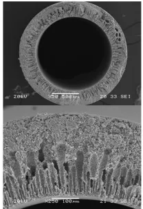
from Nextech Materials Ltd, and were used as supplied. Lithium nitrate (LiNO3, grade AR) was purchased from QREC (Asia) Sdn. Bhd and was used as supplied. Ethanol was used as solvent. The anode supported HFs used in this work were fabricated using phase inversion method as stated elsewhere [8]. The HFs precursor comprised of a mixture of NiO-CGO powders and PESf in the inner layer. As can be seen in Figure 1, the cross-section of the inner layer exhibits an asymmetric structure with short finger-like structures originating from the inner surface to approximately 35% of the inner layer thickness, whereas the other 65% consists of sponge-like structure.
Figure 1 SEM images of NiO-CGO anode supported HF [8]
2.2 Preparation of CGO Doped Lithium Powder
In this stage, dopant was prepared by mixing 1, 2 and 3 mole percentage of LiNO3 which is the sintering additive into CGO. Moreover, 50% nano and 50% micron size CGO powders were used throughout the study to produce dopants. The particle size of the CGO powders were remain unchanged to ensure that it does not impact on the sintering property of CGO. Appropriate amounts of LiNO3 were weighed and dissolved in 50 mL of solvent which is deionized water using a magnetic stir bar. Appropriate amounts of nano and micron size CGO powders were then added to the nitrate solution and the solution was left for several minutes of stirring. After that, the solution was dried at 140°C for six hours to remove water and modifies the CGO powder. Schematic diagram of the procedure is shown in Figure 2.
Figure 2 Preparation of CGO doped lithium powder
2.3 Deposition of Electrolyte Thin Layer on Anode Supported Hfs
painting technique is very simple and easy deposition method. The modified CGO slurry was coated three times to ensure the anode support well covered with the electrolyte layer. After each coating process, the HFs were left to dry at 80°C for five minutes. Schematic diagram of the procedure is shown in Figure 3.
Figure 3 Deposition of electrolyte thin layer on anode supported HF
2.4 Sintering of Electrolyte Layer
In this stage, the resulting electrolyte/anode dual layer HFs were co-sintered at different temperatures to study on the sintering property of electrolyte. Total time taken for sintering was calculated based on the specific sintering profile as shown in Figure 4 and the HFs were sintered by heat treatment in a tube furnace with air flow. Sintering temperature (Tsinter) was varied from 1250°C to 900°C with the interval of 50°C.
Figure 4 Applied sintering profile for the dual layer hollow fibre
2.5 Characterization of Dual Layer Hollow Fibre
In this stage, several tests were done on the sintered HFs to understand the characteristics and performances. The tests are as follow:
2.5.1 Scanning Electronic Microscope (SEM)
SEM was done on the hollow fibers to study the morphology or the structure of the HFs after sintering process. Hitachi model TM3000 was used to capture the image of HFs. The HFs snapped in order to obtain cross-sectional and surface fractures. High resolution images of the cross-section and the surface of the HFs were taken at different magnifications.
2.5.2 Mechanical Strength Analysis
The mechanical strength of HFs were examined by three-point bending test using an Instron Model 5544 tensile tester provided with load cell of 1 kN. Dual-layer HFs were fixed on the sample holder with 30 mm distance. The bending strength (σF) is calculated using the following equation:
where F is the measured load at which fracture occurred (N); L,
Do, Di are the length (m), the outer diameter and the inner
diameter of the HFs (m), respectively8.
3.0 RESULTS AND DISCUSSION
3.1 General Morphology of Dual Layer Hollow Fibre
For ceramic membranes with dual-layer structures, especially when the two layers are made of different materials, co-sintering is always challenging due to the different sintering behaviors of the membrane materials which possibly can form cracks. As for this study, the anode is made up of NiO-CGO, whereas electrolyte is made up of LiNO3-CGO. When heat is applied, deviation in the thermal expansion coefficient of the electrolyte and anode materials can cause variations in the expansion rate. This can possibly cause the micro-cracking in the structure of electrolyte layer as shown in Figure 5. This statement is also strongly supported by the finding made in the previous studies. Two dimensional mechanics of cracks in sintering thin films has been analyzed by Jagota and Hui [9]. They predicted condition for crack growth in sintering thin layer are related to the friction of the layer on the substrate and relative neck growth rate. However the continuous mechanic analysis has difficulty in explaining how crack initiates. In recent years, some progress has been made in the fundamental understanding of rack initiation by using discrete element modelling (DEM). For example, Henrich
et al. [10] found that crack initiation in the constrained film is related to particle rearrangement. If rearrangement is suppressed, cracks tend to form more easily because of increased local
stresses. Rasp et al. [11] found that particle rearrangement also
affects the delamination of ceramic strips where an easier particle rearrangement inhibiting delamination at the edges of the ceramic
strips (2012). The work of Martin et al. [12] led to the conclusion
that, although geometrical constraint is necessary for a defect to grow into a crack, the presence of an initial defect is not a necessary condition to initiate cracks. Nevertheless, there is still a lack of direct experimental evidence concerning how cracking is initiated.
available for comparison against the adhesion strengths measured in this study.
3.2 Effect of Sintering Temperature on the Microstructure of Dual-layer
For ceramic membranes, use of higher sintering temperature contributes normally in improving the mechanical strength of the membrane, while in the meantime decreases the porosity and increases the resistance to gas permeation. The dual-layer hollow fibres developed in this study is for the construction micro-tubular SOFC, which requires reasonably strong mechanical property for the deposition of remaining component such as cathode. It is also important to have a highly porous anode and dense electrolyte layer. As a result, the effects of sintering temperature on the developed dual-layer hollow fibres have been investigated.
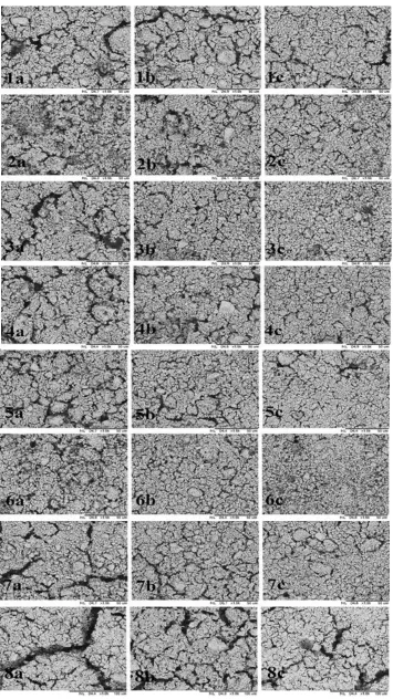
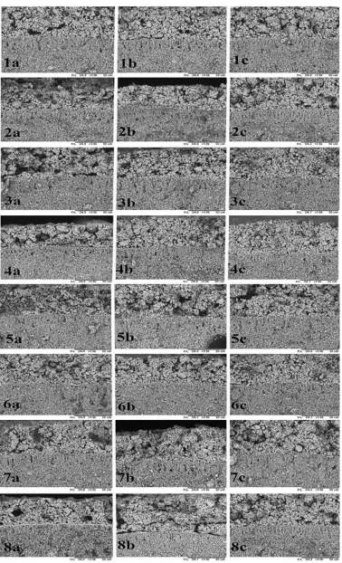
Figure 5 illustrates evolution of the surface morphologies at different sintering temperatures between 900°C and 1250°C. It has been seen that porosities of the electrolyte layer are reduced greatly when the sintering temperature is increased.
Obvious changes in the surface morphology take place at about 1000°C, and the interconnected pores are observed from the membrane surface. When the sintering temperature increased to 1150°C, the electrolyte layer becomes almost fully dense. As the temperature goes higher, the grain size increased considerably. On further increasing the sintering temperature up to 1250°C, micro-pores clearly observed again with the possible reason of micro-cracks.
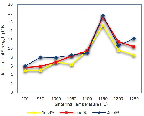
The effect of sintering temperature on the mechanical property of the developed dual-layer hollow fibre, which was investigated by a three-point bending test, is shown in Figure 7. As can be seen, a significant increase of approximately 68% in the mechanical strength was observed when the sintering temperature rises from 900 to 1100°C. In addition, sudden hike was also recorded 1150°C where the value increases by 77.4%. The optimum mechanical strength of the developed hollow fibre is 17.577 MPa which was sintered at 1150°C. At higher temperature, the ceramic particles fuse and develop into larger and closer grains with stronger bounding between them, hence giving higher mechanical strength. However, further increase in the sintering temperature would lead to micro-cracking in the structure, and thus reduce the mechanical strength, which was observed for the samples co-sintered at 1200°C and higher. This also supported by the SEM images in Figure 5, where, as the sintering temperature increases the electrolyte layer becomes denser.
3.3 Effect of Sintering Additive on the Microstructure of Dual-Layer HF
Figure 5 and 6 also illustrate the effect of sintering additives on the sintering property of the developed dual-layer hollow fibres. All the hollow fibres sintered at 900°C to 1250°C with the interval of 50°C. However, the microstructure and grain boundary phase were significantly different depending on the content of LiNO3. The content LiNO3 varied from 1 to 3 mol% as sintering additive. The SEM micrograph of the hollow fibre with 1 mol% LiNO3 reveals a microstructure consisting of fine CGO grains. Jason D. Nicholas has stated in his study that a dopant’s effectiveness should simply be a matter of its ability to form a beneficial liquid phase and/or its ability to improve the CGO near grain boundary flux. It is thought that only fine grains were formed due to the insufficiency of liquid phase through which the mass transport occurred. The images also reveals the at 1 mol%
of LiNO3, the layer does not attain sufficient densification within 900°C to 1250°C. When the amount of LiNO3 was increased to 2 mol%, the grains become somewhat bigger, but still dense layer was not observed. This indicates that 2 mol% LiNO3 was still not sufficient enough for extensive growth of the CGO grains. As the amount of LiNO3 further increased to 3 mol%, the morphology changed remarkably. Less micro pores were observed, implying 3 mol% of LiNO3 generated a sufficient amount of liquid phase for the extensive grain growth. Based on the SEM images, sufficient densification was achieved at 1150 °C.
Figure 7 also describes the effect of LiNO3 on the mechanical property of developed dual-layer hollow fibres. Based on the figure, as the mol% of LiNO3 increases, the mechanical property of the hollow fibres also increases. Even though the variation is not much between 2 mol% and 3 mol%, the difference is very significant compared to 1 mol% of LiNO3. As the presence of LiNO3 enables better densification, the structure becomes more stable and possesses better mechanical strength.
4.0 CONCLUSION
Figure 7 Bending strength of LiNO3-CGO/NiO-CGO dual layer HFs at different sintering temperatures
Acknowledgement
The authors gratefully acknowledge financial support from Ministry of Science, Technology and Innovation Malaysia under
Sciencefund program (Project Number: R.J130000.7942.4S033) and Universiti Teknologi Malaysia under Research University Grant grant ((Project Number: Q.J130000.2542.03H14). The authors also acknowledge technical and management support from Research Management Centre, Universiti Teknologi Malaysia.
References
[1] J. Will, A. Mitterdorfer, C. Kleinlogel, D. Perednis, and L. J. Gauckler. 2000. Solid State Ionics. 131: 79–96.
[2] A. Isenberg. 1981. Solid State Ionics. 3–4: 431–437.
[3] Herring and Conyers. 1950. Journal of Applied Physics. 21(5): 437. [4] R. Fuentes and R. Baker. 2008. International Journal of Hydrogen
Energy. 33(13): 3480–3484.
[5] C. Kleinlogel, and L. J. Gauckler. 2000. Solid State Ionics. 135: 567– 573.
[6] Pei-Lin Chen, and I-Wei Chen. 1996. Journal of the American Ceramic Society. 79(12): 3129–3141.
[7] T. Zhang. 2004). Solid State Ionics. 167(1–2): 203–207.
[8] M. H. D. Othman, Z. Wu, N. Droushiotis, G. H. Kelsall and K. Li. 2010.
Journal of Membrane Science. 360(1–2): 410–417.
[9] A. Jagota and C. Y Hui. 1991. Mechanics of Materials. 11(3): 221–234. [10] B. Henrich, A. Wonisch, T. Kraft, M. Moseller, and H. Riedel. 2007.
Acta Materialia. 55(2): 753–762.
[11] T. Rasp, C. Jamin, A. Wonisch, T. Kraft, and O. Guillon, O. 2012.
Journal of the American Ceramic Society. 95(2): 586–592.