Removal of Impulsive Noise from Long Term
Evolution Handset Using Double Detection
Method
Akhil S. Kulkarni, Dr. D.G. Khairnar
M.E (Communication Networks), Dept. of E&TC, D.Y.Patil College of Engg, Akurdi, India
Head, Dept. of E&TC, D.Y.Patil College of Engg, Akurdi, India
ABSTRACT: The Long Term Evolution (LTE) handsets operates in the frequency bands which are being affected by the impulsive noise (IN). The double detection method is used to remove IN from the LTE handset. This method uses the conventional threshold method where threshold selection is the major aspect. The LTE handsets consists of two transmitting and receiving antennas, so the output should be considered by the comparison of the two different frequencies received at the receiver. The better signals within the threshold level is mainly considered.
KEYWORDS: LTE, space time coding, orthogonal frequency division multiple access (OFDMA), multiple input multiple output(MIMO), IN, cellular radio
.
I. INTRODUCTION
LONG TERM EVOLUTION
LTE is designed only to support the packet switched services [2]. LTE is mainly used to provide the internet protocol connectivity between the user equipment and the packet data network. LTE works in the frequency range of 700 to 2600MHz and it provides 20 MHz of frequency width [1]. Here to eliminate the IN in double detection method different modulation schemes are being used i.e. single carrier frequency division multiple access (SC-FDMA) for uplink &OFDMA for downlink [1]. Here the work is done on downlink of LTE. The transmitter is base station (eNodeB) and receiver is user equipment. In LTE MIMO is used for transmission of data. Here in this paper only MIMO 2*2 deployment is considered [1].
IMPULSIVENOISE
IN consists of relatively short duration “ON/OFF” noise signals, caused by variety of sources [9]. Mostly IN occurs at very high frequency level up to 7 GHz. But the effect is mainly observed below 3GHz. The IN mostly affects in wideband radio communication. The IN generated due to lightening, transient in transformers, induction motors, sparks produced by manifold, dc electric motors, ignition noise from the spark plug of the petrol engines, arc welders, etc. As the bandwidth of the IN is wider than the communication channel, it is assumed that the impulsive noise pulse duration is shorter than the sampling period i.e. each IN pulse affects only one single sample [9].
MIMO
II.BACKGROUND
ADDITION OF IN:
MIMO systems combine more technical resources than just spatial diversity which is used in double detection method. Here research was done on the effect of space–time coding when IN enters a MIMO receiver.
SPACE TIME BLOCK CODING AND SPACE FREQUENCY BLOCK CODING
Let us consider a MIMO wireless communication system, alamouti coded [4], [7], with two transmit antennas and
two receive antennas. Let us suppose that we want to transmit two consecutive symbols, i.e.
s
1&s
2 The Alamouti transmission matrix is* 1 2 * 2 1
s
s
c
s
s
………….. [1]
In the first time slot,
Tx
1 transmitss
1andTx
2 transmits
s
2*,where *stands for the complex conjugate. In thesecond timeslot,
Tx
1 transmitss
2, andTx
2 transmitss
1*.The symbols in time domain with
s
1&s
2onTx
1 the original data are transmitted without any modification.Therefore, the subcarrier mapping for
Tx
1 results in the inverse discrete Fourier transform as, 2 1 1, 01
*
*
n N jm N m n nX
s
e
N
……….. [2]Where N is the total number of subcarriers, n is the subcarrier index, and m is the sample index of the time signal. The subcarrier mapping for
Tx
2 is1 2 (2 1) 2 (2 ) 2
2, 2 2 1
0
1
*
*
*
N n n jm jm N Nm n n
n
X
s
e
s
e
N
……… [3] SPACE TIME BLOCK CODING AND IN
At the receiver [4], the signal in antenna iwhen two signals at two consecutive time slots (t = 1, 2) received is
1, 1 2 ,1 1, * *
2, 2 1 ,2 2,
i i i
i i i
y
s
s
h
v
y
s
s
h
v
……….. [4]
Where
y
k i, is the whole received signal at time slot kat antenna i.s
kis the subcarrier generated at time slot k.h
i j,represents the channel coefficient from transmit antenna j to receive antenna i. Moreover,
y
k i, is the noise contribution at time slot k, received at antenna i.Above equation can be rewritten as
1, ,1 ,2 1 1,
* * *
2, ,2 ,1 2 2,
i i i i
i i i i
y
h
h
s
v
y
h
h
s
v
………. [5]
By multiplying with
A
Hi we get which has orthogonal property as,1, 1, ,1 ,2
* * *
2, 2, ,2 ,1
i i i i
i i i i
z
y
h
h
z
y
h
h
……….. [6]
Methodology consists of the following points.
THRESHOLD DETECTION AND BLANKING METHOD
In double detection method the threshold is set to zero if the value of the signal amplitude exceeding the threshold value [10]. The threshold value is set in terms of the root mean square value of the amplitude of the signal received.
Here the threshold value is fixed as a multiple of the RMS value of voltage amplitude.For ex. M=4 it means that the threshold is fixed at four times the RMS value.
BLANKING VSCLIPPING
Blanking and Clipping methods are majorly used when the value of the threshold exceeds than the fixed value. In blanking the samples exceeded than the threshold value are spread out in time domain so as to minimize the effect of the IN. In clipping the samples are made equal to zero exceeding the threshold value. The double detection method supports blanking instead of clipping [5].
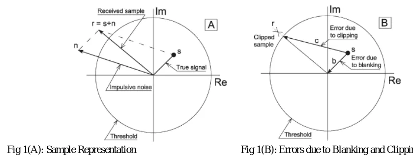
In Fig. 1A, it can be seen that the complex time-domain representation of s, which is the true sample that should be received. The IN, i.e., n, enters the receiver at the same time. The actual sample that received was r = s + n. The circumference is the amplitude threshold that set to detect IN.
The OFDM receiver obtains the subcarriers after performing a fast Fourier transform (FFT). Therefore, the energy of the IN pulse n is spread among the symbol subcarriers, and it may cause decoding errors; the more errors, the more energy it has.In Fig. 1B, the results after the Clipping and Blanking were observed. During clipping, error c is added to the signaland during blanking, the error b is added as shown in the figure. We can consider any of these two errors introduced by n because both have less energy. From the figure we can easily say that error b will be having less energy than error c. However, blanking has the limits such as if too many samples within the OFDM symbol were affected by IN, the energy of the added contributions of many blanking vectors such as b might cause decoding errors in the subcarriers after the FFT.
In Fig. 1B, clipping is accomplished at the amplitude of the threshold level. Clipping could also be accomplished at the RMS level, i.e., all samples exceeding the threshold would be clipped to the RMS level (keeping their angle). Clipping at the RMS level offers better results than clipping at the threshold level.
Fig 1(A): Sample Representation Fig 1(B): Errors due to Blanking and Clipping
USING RECEIVE DIVERSITY TO ELIMINATE IN
The above two methods were single detection methods. However, the procedure presented by the researchers is to monitor and blank high-amplitude samples detected in both receive antennas at the same time and called as double detection method [1].
1) Receive antennas.
2) Radio frequency tuning, intermediate frequency conversion and all the tasks previous to sampling are used. 3) Continuous signals
s t
1( )
ands t
2( )
are simultaneously sampled with period T. Discrete signalss n
1[ ]
ands n
2[ ]
are obtained.4) The samples of
s n
1[ ]
ands n
2[ ]
are checked out to see if their amplitude exceeds the detecting threshold TH. 5) The logical outputs of the latter stage go through an AND gate. The output is a logical variable called IMP that determines if the sample simultaneously received ins n
1[ ]
ands n
2[ ]
is IN or not.6) If high amplitude was detected in
s n
1[ ]
ands n
2[ ]
at the same time, the corresponding samples are zeroed in both signals. If not, both signals stay without modification.LTE systems take advantage of receive diversity. In a MIMO 2 × 2 deployment, the signal is received on two antennas at the same time.
Fig 2: Block Diagram of Double Detection Method
IV.SIMULATION RESULTS
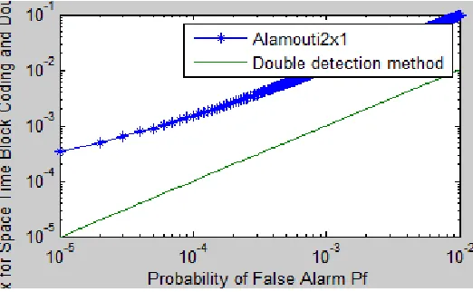
1) Here first the probability of false alarm is calculated with respect to the Alamounti coding. It is clearly shown that the probability of false alarm rate in this method is greater for minimum correlation in space time block coding. The Probability of false alarm rate should be considered whenever there is need of eliminating the noise from the signals.
V.CONCLUSION
The method consists of eliminating those received samples in which high amplitude is simultaneously detected at both receive antennas. The space–time coding of MIMO processing has an influence over the received IN. The double detection method is more effective when the signals at both antennas are uncorrelated and when an aggressive threshold is set for detection. The BER for double detection is much lower than BER for space time coding.
REFERENCES
[1] Pablo Torío and Manuel García Sánchez, “Elimination of Impulsive Noise by Double Detection in Long-Term Evolution Handsets”, IEEE transactions, vol. 64, no. 7, july 2015
[2] Third Generation Partnership Project, “Specification of Group Radio Access Network; Evolved Universal Terrestrial Radio Access (E-UTRA); Physical Channels and Modulation (Release 10)”, V10.1.0 (2011-03), 2011
[3] M. Naser and B. L. Evens,”Low complexity EM based decodind for OFDM system with Impulsive Noise”, in Proc., ASILOMAR 45th conference signals, syst. Comput., pp 1-5, Nov. 2011.
[4] I. Berenguer and X. Wang, “Space–time coding Signal processing & for MIMO communications”, J. Comput. Sci. Technol., vol. 18, no. 6, pp. 689–702, Nov. 2003.
[5] S. V. Zhidkov, “Analysis and comparison of several simple impulsive noise mitigation schemes for OFDM receivers”, IEEE Trans. Commun., vol. 56, no. 1, pp. 5–9, Jan. 2008.
[6] M. Nassar and B. L. Evans, “Low complexity EM-based decoding for OFDM systems with impulsive noise”, in Proc. ASILOMAR 45th Conf.Signals, Syst. Comput., pp. 1943–1947, Nov. 2011.
[7] S. Alamouti, “A simple transmit diversity technique for wireless communications”, IEEE Areas Commun., vol. 16, no. 8, pp. 1451–1458, Oct. 1998.
[8] T. Jiang and Y. Wu, “An overview: Peak-to-average power ratio reduction techniques for OFDM signals”, IEEE Trans. Broadcast., vol. 54, no. 2, pp. 257–268, Jun. 2008.
[9] A. Shukla, “Feasibility Study Into the measurement of man-made noise”, Defense Evaluation Research Agency (DERA): Radiocommun. Agency, U.K. Min. Defence, Mar. 2001.