Development of the Three Dimensional Fatigue Analysis Procedure for Major
Components of the New Advanced Power Reactor
Taesoon Kim1), Chankook Moon2) and Byongsup Kim2)
1) Nuclear Engineering & Technology Institute, Korea Hydro & Nuclear Power Co., KOREA
2) Principal Researchers, Nuclear Engineering & Technology Institute, Korea Hydro & Nuclear Power Co., KOREA
ABSTRACT
Fatigue has been considered as the important failure mechanism to assess integrity and design life of nuclear power plant. For the class 1 (one) components, fatigue analysis procedure and standard fatigue design curve(S-N curve) are described on ASME code section III NB, which have to be performed to meet the integrity of components at the design stage. However, the existing ASME fatigue design curve is difficult to consider environmental fatigue effects due to the life extension of the nuclear power plants in operation and the long-lived plant design. Therefore, a number of researches and discussion to find the technical solution for these problems are continued up to now. In this study, fatigue analyses in detail using the three dimensional modeling for the fatigue-weakened components were performed to develop the optimized fatigue analysis procedure. And the cumulative usage factors (CUF) are calculated to assess environmental effects on the plant life comparing with other reference values.
ITRODUCTION
In the design for class 1 components of nuclear power plant, fatigue has been considered as the important failure mode that has to be necessarily met by fatigue design criteria. And fatigue analysis procedure and standard fatigue design curve are described on ASME code to evaluate the integrity of components at the design stage. As the life extension of nuclear power plants in operation and the long-lived plant design are being progressed in domestic and overseas nuclear power plants, the fact which the existing ASME fatigue design curve can not afford fatigue effects sufficiently comes to the fore.[1]
Therefore the fatigue integrity evaluation procedure for major components should be improved by removing its conservatism and using more detailed analysis method. In order to solve these technical problems, a number of researches and discussion including fatigue life tests and analytical methods have been performed so far.
Researches related to the fatigue life test under the high-temperature and water chemistry condition have been performed mainly in the United States and Japan and were in the process in some of European countries and South Korea recently. Particularly some of them, O. K. Chopra (United States), M. Higuchi (Japan), C. H. Jang, and H. C. Cho (South Korea) et al. have contributed to the production of the results of fatigue life test at home and abroad. Concerned with carbon steel, low alloy steel, and austenitic stainless steel, O. K. Chopra have presented the model to predict the fatigue life from fatigue curve test results [3,4] and M. Higuchi suggested the fatigue life correction factors from his research results.[5,6]
In this study, we suggested the detailed fatigue analyses procedure to perform the three dimensional analysis of the fatigue-weakened components. So fatigue analysis for the steam generator economizer feedwater nozzle were performed to develop the fatigue analysis procedure by removing conservative factors included in the existing fatigue integrity evaluation procedure. Fatigue analyses in detail using the three dimensional modeling for the chemical volume and control system (CVCS) charging inlet nozzle were performed to develop the optimized fatigue analysis procedure and their results are compared with other reference values.
FATIGUE ANALYSIS PROCEDURES
Fatigue Analysis by ASME Code
In ASME code section III NB-3200, fatigue analysis procedure is described on Fig. 1. First of all, we determine the stress differences, S and the alternating stress, Safor each condition of normal operation. Next, the effects of local structural discontinuities shall be evaluated for all conditions using stress concentration factors determined from theoretical and experimental, or numerical stress analysis techniques.
Fig. 1 Procedure of ASME fatigue analysis.
If there are two or more types of stress cycle which produce significant stresses, their cumulative effects shall be evaluated, and the cumulative fatigue usage factors, U are presented as the Equation (1). Here the cumulative fatigue usage factor Ushall not exceed 1.0.
∑
=
=
k
i i
U U
1
(1)
Detailed Fatigue Analysis
In this study, the detailed fatigue analysis procedure using the three dimensional finite element modeling was developed as stipulated in next steps below. First, thermal analysis for the global transients using ANSYS code is performed, and the target zones for fatigue analysis are selected from the results of thermal analysis because the thermal gradient of the zones are higher than other zones.
From the thermal distribution by thermal analysis and the applied pressure value by the design specification, the stress intensity is calculated for each transient. If the stress intensity is obtained for the global transient that will be occurred in the operation period, the alternating stress intensity Salt for global transient and the frequencies for the life time is estimated by the Rain-flow method of ANSYS modules.
By the way, as the ANSYS module can not consider the ratio of the modulus of elasticity given on the design fatigue curve to the value of the modulus of elasticity used in the analysis, we developed the FACAL code that is composed of FORTRAN programming language and can calculate the ratio of the modulus of elasticity and the cumulative fatigue usage factors [7]. The fatigue analysis procedure developed in this study is presented briefly in Fig. 2.
In this study, the detailed fatigue analysis procedure using the three dimensional finite element modeling is developed as follows. First, thermal analysis for the global transients using ANSYS code is performed, and the target zones for fatigue analysis are selected from the results of thermal analysis. From the thermal distribution by thermal analysis and the applied pressure value by the design specification, the stress intensity is calculated for each transient. If the stress intensity is obtained for the global transient that will be occurred in the operation period, the alternating stress intensity Salt for global transient and the frequencies for the life time is estimated by the Rain-flow method of ANSYS modules to calculate the cumulative fatigue usage factors.[8]
FATIGUE ANALYSIS
Fatigue Analysis for CVCS Charging Inlet Nozzle
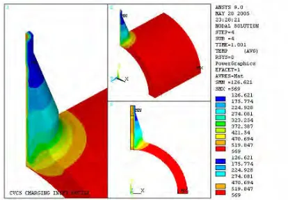
In order to perform the sample fatigue analysis, CVCS charging inlet nozzle is selected as the target. The inner diameter of the charging inlet nozzle is 30.0 inches. and the inner diameter of the nozzle connected to the cold leg 2.0 inches. For the thermal analysis for the charging inlet nozzle, the outer surface of the nozzle and pipe are assumed as the insulation material for a perfect adiabatic condition. And by symmetric condition, the quarter (1/4) model of the component is modeled with the SOLID70 elements. Fig. 3 shows the thermal distribution for the event of “NSSS operation with the control system in the manual mode at 5-100” resulted from thermal analysis of CVCS charging inlet nozzle.
Fig. 3 Thermal distribution of CVCS charging nozzle.
The model to analyze the stress intensity is composed of 34,464 nodes and 36,970 elements and the element type is the SOLID45 element which is the three dimensional structural solid element and has 4 nodes. To consider the feature of deformational behavior, the longitudinal (z-directional) displacement of the nozzle center and the transverse (x-directional) displacement are constrained. And the y-directional displacement of the center surface is constrained by the symmetric boundary condition. Fig. 4 shows the distribution of the stress intensity for the ‘NSSS operation with the control system in the manual mode at 5-100’ event which is one of the main transients to affect the fatigue analysis results.
To perform the fatigue analysis for the charging inlet nozzle, the fatigue-weakened location must be selected adequately by analyzing the thermal analysis results. The cumulative fatigue usage factors calculated at cut locations of the charging inlet nozzle are compared with the reference results as shown in Fig. 5.
Fig. 5 Cut locations of CVCS charging nozzle.
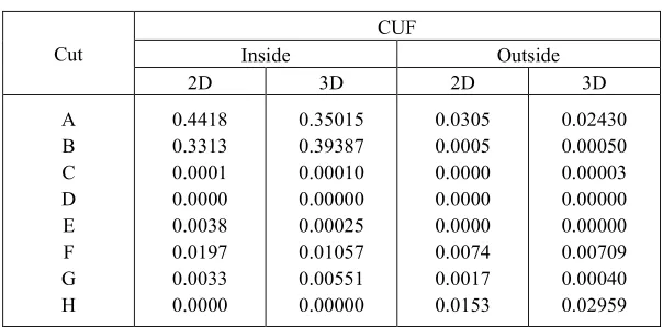
Table 1. Fatigue analysis results for CVCS nozzle.
CUF
Inside Outside
Cut
2D 3D 2D 3D
A B C D E F G H
0.4418 0.3313 0.0001 0.0000 0.0038 0.0197 0.0033 0.0000
0.35015 0.39387 0.00010 0.00000 0.00025 0.01057 0.00551 0.00000
0.0305 0.0005 0.0000 0.0000 0.0000 0.0074 0.0017 0.0153
0.02430 0.00050 0.00003 0.00000 0.00000 0.00709 0.00040 0.02959
Fatigue Analysis for Economizer Feedwater Nozzle
As stated above, the purpose of this study is to develop the optimized fatigue analysis procedure which is removed its conservatism by using the more detailed analysis method. In order to meet our goal, the steam generator economizer feedwater nozzle of the new advanced power reactor components is selected as the component for the sample problem. Though the steam generator economizer feedwater nozzle is not the class 1 component to consider environmental effects, the fracture possibility is very high because its CUF value is larger than other components. The length of the shell and the safe end of the steam generator economizer feedwater nozzle used in this analysis is 30.0 in. and 15.0 in. respectively.
Table 2. Analytical conditions of S/G feedwater nozzle.
Loading Material of
nozzle
Sm (ksi)
S-N Curve (ksi) 2-D Pmax, Pmin at Max. Thermal Stress SA508 Cl.1 30.0 UTS ≤ 80 CASE1 Pmax, Pmin of Transient SA508 Cl.1 26.7 UTS ≤ 80 CASE2 Pmax, Pmin of Transient SA508 Cl.2 30.0 UTS ≤ 80 CASE3 Pmax, Pmin of Transient SA508 Cl.2 30.0 UTS = 90(interpolated) CASE4 Pmax, Pmin at Max. Thermal Stress SA508 Cl.2 30.0 UTS ≤ 80 CASE5 Pmax, Pmin at Max. Thermal Stress SA508 Cl.2 30.0 UTS = 90(interpolated)
First of all, to analyze thermal stress applied on the economizer feedwater nozzle, the finite element model of the nozzle is modeled as shown in Fig. 6. By symmetric condition, the 1/4 model of the nozzle is modeled with the SOLID70 elements which are composed of 7,548 elements and 9,548 nodes. Fig. 6 shows the distribution of the stress intensity for the ‘plant heat up’ event which is one of the main transients to affect the fatigue analysis results.
Fig. 7 presents the cut locations of the economizer feedwater nozzle which must be selected adequately by analyzing the thermal analysis results and performed the fatigue. For 5 different cases, the cumulative fatigue usage factors calculated at the cut locations of the economizer feedwater nozzle are listed in Table 3. As shown in Table 3, cumulative fatigue usage factors have the smallest values when analytical conditions such as loading, material, and design fatigue curve are optimized.
Fig. 6 Stress distribution of economizer f/w nozzle.
Table 3. CUFs for 5 analytical cases at cut location of economizer f/w nozzle.
CUF (inside) Cut
2-D CASE 1 CASE 2 CASE 3 CASE 4 CASE 5 A B C D1* D2* E1 E2 F1 F2 0.0132 0.0156 0.4319 0.9675 0.5587 0.9106 0.4710 0.0073 0.0059 0.0051 0.0120 0.1882 2.7852 0.5307 3.8524 0.3662 0.0526 0.0303 0.0076 0.0201 0.2186 1.4967 0.6511 1.9706 0.4867 0.0682 0.0408 0.0051 0.0120 0.1882 1.4402 0.5307 1.9442 0.3662 0.0526 0.0303 0.0071 0.0186 0.2117 0.8789 0.6116 0.9486 0.4713 0.0374 0.0217 0.0048 0.0110 0.1822 0.7857 0.4903 0.8594 0.3519 0.0272 0.0171 * 1 : Longitudinal section 2 : Transverse section
CONCLUSION
Based on the three dimensional finite element modeling, the fatigue analyses for CVCS charging inlet nozzle of the new advanced power reactor components are performed to define the conservatism of fatigue analysis procedure and the detailed fatigue analysis method is developed from the results. Cumulative fatigue usage factors calculated by the detailed fatigue procedure are compared with the reference results. And By using the procedure, we have performed the fatigue analysis for the steam generator economizer feedwater nozzle and developed the optimized fatigue analysis procedure which conservative factors included in the existing fatigue integrity evaluation procedure are removed. We found that cumulative fatigue usage factors calculated by the fatigue analysis procedure developed in this study had lower values than the reference values.
REFERENCES
1. ASME, ASME B&PV Code, Section III, “Rules for Construction of Nuclear Power Plant Component,” 1998 Edition with 1998 Addenda in Effect as of Dec. 31, 1998.
2. NRC, “Application of NUREG/CR-5999 Interim Fatigue Curves to Selected Nuclear Power Plant Components,” NUREG/CR-6260, 1995.
3. Chopra O.K. and Shack W.J., “Low-cycle Fatigue of Piping and Pressure Vessel Steels in LWR Environments,” Nuclear Engineering and Design, Vol. 184, 1998, pp. 49-76.
4. Keisler, J.M., Chopra, O.K. and Shack, W.J., 1996, "Statistical models for estimating fatigue strain-life behavior of pressure boundary materials in light water reactor environments,“ Nuclear Engineering and Design, Vol. 167, 1996, pp. 129-154.
5. Higuchi, M., "Revised proposal of fatigue life correction factor Fen for carbon and low alloy steels in LWR water environments,“ Journal of Pressure Vessel Technology, Vol.126, 2004, pp. 438-444.
6. Higuchi, M., "Development of evaluation method of fatigue damage on operating plant components in considering environmental effect of LWR coolant," Proceedings of 3rd International Conference on Fatigue of Reactor Components, Seville, Spain, October 2004.
7. Kim B.S. and Kim, T.S., “Development and Application of Detailed Procedure to Evaluate Fatigue Integrity for Major Components Considering Operating Conditions in the Nuclear Power Plant,” J. of the Korean Society of Safety, Vol. 21, No.6, 2006, pp.20-25.