EXPERJMENTAL AND NUMERICAL STUDIES OF'FLT]IDIZATION IN A
CIRCI]ILATING FLUIDIZED BED
Ahmad Eussainr*, Farid Nasir Anit, Amer Noralin Darusl, Azeman Mustafaz'
rFaculty of Mechtnical Engineering, Univ€rsiti Teknologi Malaysia, Skudai 81310, Johor, Malaysia uFaculty ofChemical anal Natural Resources Engrneering, Universiti T€knologi Malrysia, Skudai 81310,
Johor, Malaysia
*Corresponding Author: Phone: +607-5534785' tr'tx: +607-5566159 *Email: qbse{[email protected],lqy
ABSTRACT
The hydrodynamics of a circulating fluidized bed (CFB) sers is highly complex and is shongly influenced by the distribution of particles, which is govemed by the amount ofparticles, size, folm (e.g. spherical or elliptic), density, etc. The CFB riser colunm has 265 mm (width),72 mm (depth) closs-section (rectangle) and 2.7 m heigit. The ris€r is made up of interchangeable Plexiglas colunms. In this study the influeDce of the amount of particles on the flow pattem in the CFB system is investigated. The particle loading is increased ftom a dilute to a dense and gas_particle flow is analyzed.
Simulations were done using FLUENT 6.1, a CFD package by Fluent lnc Palm shell particles and air were used as the solid and gas phases, respectivelyr The simulations were done using th€ geometrical conflguration ofa CFB test rig at the Universiti Telalologi Malaysia ([ITM).
The result disousses the variation of velocity contours, along the riser colunm and in the riser exit geomefy. The effect is significant in the upper region of the dser colurm and the velociry contous are also influenced by the exit geometry. Simulations results predict that the dser exit cause an upstream exit r€gion of increased solid volume fraction. Expe mental and computational results ar€ matched to rcasonable agreement. Experimental findings have also helped to refme the nume.ical modeling of multiphase CFB system.
Ke)'words: CFD, FLUENT, hy&od)'namics, multiphase flow, riser exit, velocity contows INTRODUCTION
Despite their widespr€ad applications of the CFB, much ofthe development and design of fluidized bed reactors have b€m empi cal in nature. This is due to the complex flow behaviour of gas-solid flow in these systems which makes flow modeling a challenging task.
The fundamental problem encountered in modeling hydrodynamics of fluidized bed is the motion of the two phases of which the interface is unknown and hansient, and the interaction is understood only for a limited range of conditions. [1]
Due to the mathematical complexities of the lon-linearity ofthe equations and in defining the
interpenetrating and moving ihase boundaries make numerical solutions very difficult [2] Computational fluiddlnamicJ(CFD) is emerging as a very promising new tool in modeling hydrod)'namics While it is now a standard iool for single-phase flows, it is at the development stage for multiphase systems, such as
Iluidized beds. [3]
simulations wele performed by [4] in fluidized bed with the presence of air and sand using FLUENI4.56. The research was iarried out at various velocities. The pedormance ofthe bed was better at higher gas velociti€s.
Many researchers have simulated three-dimensional two fluids cFD model of gas paflicle flow in the cFB usin; the code CFX-4.3. The turbule[ce was mod€led by k-e turbulence model ill the gas phase and a fixeJ particle viscosity model in the solid phase This CFD model showed good ageement with the experiment. [5]
A study ofgas/pafticle flow behavior in the riser section ofa circulating fluidized bed (CFB) was done u.itrg FLUet{a +.a. nluid Catallic Cracking (FCC) particles and aiI were used as the solid and gas ohasis. respectively. The computational r€sults showed that the inlet and outlet design have significant effects on the overall gas and solid flow pattems and clusler formations in lhe riser' [6]
CFB USED FOR SIMTITATION
Figuelsho{stheschematicsofthecFBusedfolsimulation.ThisCFBisstillinthecommissioning ohise and the experimentation is expected to start soon This system consists of an air supPly device
'(blower),
a distributor of stainless steel, a fast colunm of Plexiglas ard primary and secondary cyclones of steel anJ a solid feeding system. The riser and its exit are made of Plexiglas to see the flow behaviour and to pedolm image analysis.
Figure 1 : Ciroulating fluidized test rig at Universiti Teknologi Malaysia
The simulation-work
described
here was done on a riser of rectangular
cross-section
of265
(width) x 72 (depth) x 2649 (height) mm'. The operating parameters
w€re chosen
to so give
d)aMmical
similaxi8 with a large CFBCs. Simulalion was done using FLUENT 6 1' a
computational
fluid dlnamics (CFD) package
by Fluent Inc lTl. Sand particles and air were used
as the solid and gas phases,
respectively. The parameters
used in the simulation work are being
sunrnadzed
in Table 1.
Table
l: Parameters
used
in simulation
work
Parameter Ratrge ofvalues
Riser dimensions
2649
(L) X 265
(w) mm
X 72
(T) mm
Gas velocity 5 m/sParticle velocitv
Properties of air Densit: 1.225 kg m-i
Viscositv: 1.79 x 10⁻⁵ kq/m.s Properties of
Darticle
Density: I 600 kg m'' Diameter: l00X I 0-6 m Height ofthe
particle inlet fiom distributor
200 mm
Exit Geometries Simulated
fught angle exit, right angle exit with bame and blind T exit.
Volume fraction of oarticles
0.03 used as the Algebraic Slip Mixture Model gives good prediction within 10% volume fraction ofsand
Granular properties Particle-particle restitution coe{ficient is 0.95 Particle-wall restitution coefficient of 0.9 MultiDhase rnodel Eulerian lranular multiphase model
RISER EXIT
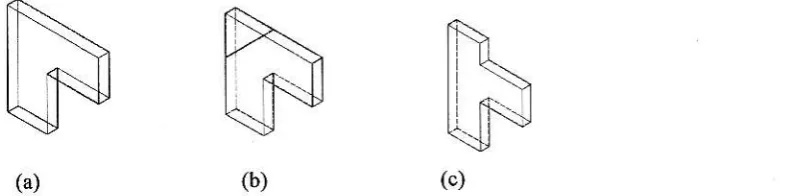
A wide range ofexperimental riser exits, which have been reported in the literature. The bend exits shown are characterized by a centerline radius of culvatule Blind T exits are chamctedzed by a roof extension height, a special case is the right angle exit, where extension h€ight is zero They are most commonly used in industrial CFBCS. These geometries are being shown in Figure 2
K
\[j.S
(b)
(4,
Figure 2: Riser Exits (a) Right angle exit (b) ght angle exit with baffle (c) blind T exit
The findings of [8] & [9] indicate that riser exits can affect the gross-behaviour of a CFB. If more solids accumulate near the riser exit then few€r solids reside in the return leg and therefore lhe static pressure head in the retum leg and consequently Ms, are smaller. The lower rate of solids circulation may cause the solids volume fraction in the riser and connector to be lower. However,
ifthe solids accumulation near the riser exit €xtends illto these components, the solids volume frnction may be larger. The upstream exit region is generally characterized by a Core/Annulus (C/A) structure, but that the solids mass flux profile may be asymmetric. Some ris€r exits appear to invoke regions near the riser wall where solids motion is upwards
The four mechanisms are: inward/outward motion, secondary flow ofthb first kind, tangential acceleration/deceleration and cavity formation. These mechanisms have shown to influence many ofthe €xperimental results. These are being discussed separately below.
a) Inward /outward motion
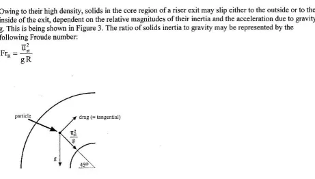
Owing to their high density, solids in the core region of a riser exit may slip either to the outside or to the inside ofthe exit, dependent on the relative magnitudes oftheir inertia and the acceleration due to gFvity g. This is being shown in Figure 3. The iatio ofsolids inertia to gravity may be represented by the following Froude nunber:
F . * = *
Figure 3: Motion of patticle in exit bend
The Froude number FrR is dependent on the cross-section average solids velocity near the top of the riser ["tand on the average radius ofcurvature R, which is defined by:
Here R"i and R- are the centerline radii of curvature at the inlet and outlet ofthe riser exit, respectively. The Froude number Fr" may be €xpected to be a function of the exit geometry, the superficial gas velocity Uo, and the superficial solids mass flow rate G"
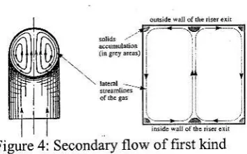
b) Secondary flow of the first kird
B€nds impose secondary flow of the first kind whereby high momentum fluid in the core moves to the outside of the bend, and slovr' moving fluid near the wall to the inside of the b€nd. As a result, the point of rnaximurn velocity lies in the outer halfofthe bend.
4
R!, + R!"
Figure 4: Secondary flow of first kind
A high momentum suspmsion in the core of a dser exit rnay invoke similar lateral pattems Figure 4 shows secondary flow pattems in a bmd exit with a square cross_section. It appears that velocity gadients are large near comers and in the middle ofthe inner and outer wall Due to their high inertia, solids may accumulate in thes€ arcas.
c) Tangential acceleration /deceleration
Tangential acceleration or decelemtion of the gas takes place in riser exits with doss_sections that change in siz€ from inlet to outlet. A fight angle exit with intemal baffle yields accel€ration followed by
deceleration, a dght angle or blind T exit ields deceleration followed by acceleration, and exits with unequal size inl€t and outlet impose a net acceleiation or deceleration
Although solids may tend to retain their initial velocity due to their high inertia, they will slow down where the gas decelerat€s and speed up where the gas accelemtes, due to drag between th€ phases. Since solids entrainment generally increases with the superficial gas velociry, a lower reflux is expected for regions of tangential accelemtion and higher reflux for regions of tangential deceleration.
d) CaYity formrtion
some riser exits may invoke cavities or reglons where solids arc disengaged from the main flow. An exampl€ is the blind T exit which invok€s a cavity in the extension. Solids which enter the extension may hit the roof or, if the extension is sufficiently long, decelerate due to drag fiom the gas Consequent build_ up of downward momentum may e[hance solids rctum to the riser. If all solids decelerate due to drag, any firther extension ofthe roof may not indease the solids volume ftaction in the riser and riser exit.
A srnall cavity or recirculation eddy may exist in the outer angle of the right angle exit, due to shear from two walls in this area. Cavities may also exist just below inlets of annular plate exits and below inlet baffles.
EULf, ruAII MI]LTIPIIASE MIXTURE MODEL
The FLUENT modeling is based on the three-dim€nsional conversation equations for mass, momentum and energy. The differential equations are discr€tized by the Finite Volume Method and ale solved by the SMPLE algodthm. As a tlrbulence model, the k-€ was employed; this consists oftwo hansport equations for the turbulent krnetic energy and its dissipation rate. The FLUENT code utilizes an unstructwed non-uniform mesh, on which the consen?tion equations for massr momentum and energy are discretized The k-e model describes the hrbulent kinetic energy and its dissipation rate and thus conrpromises between resolution of turbulent quantities and conlputatlonal time. The various FLUENT models used in
simulations arc beins tabulated in Table 2.
Table 2: List of FLUENT Models used in simulatlon
Model S€ttings
Space
2D
Time Steady
Viscous Standard k-epsilon turbulmce model Wall Tr€atment Standard Wall Functions MultiDhase Model Eulerian Multiphase Model
In the FLUENT computer progtam that the goveming equations w€re discretized using the finite volume teclmiqu€. The aliscretized equations, along with the initial and bounda.ry conditions, were solved to obtain a numerical solution.
The model used for simulating the gas-solid flow is the Eulerian Multiphase Mixtur€ Model (EMMM) The EMMM solves the continuiry equation for the mixtue, the momentum equation for the mixtuf€, and the volume fraction equation fo! the secondary phas€, as well as an algebmic expression for the relative velocity.
By using the mixture theory approach, the volume of phase q, Vo is defined by
V = f a t t Y
9 J / ' taltd L d q = |
q = 1
The effeclive density o t phase qis p=d o Po Where pq is th€ physical density ofphase .
ConservttiYe Equations
The general consewation equations liom which the solution is obtained by FLUENT are being Fesented below:
The continuity equation for phase q is
i{"" o,t+v
.ta,
c"n;-l*",
O t p _ l
where ia is the velocity ofphase q and tit e,t a;r1?.r^cIerizqs the fi]f;ss transfer ftom the pd to qs phase.
Frcm the mass co[seflahon we can get:
h * = - h *
and rh ,o =O
lntemarional Energy Conference, Jakana 5-? Augusl2005
Usually, the source term ( t ir{ ) on t}e right hand side of equation is zero
The momentum balance for phase q yields
a .
d1(tr o poiol- Y.1a, Poio i"\-- o, YP +
. 1 / , \
v . r q , d q pq E r L\R eq - n,,vo l+
d4 pq \r a + r W.q + r "^.q l
Where % is the q'phase stress-shain tensor.
i , = a o p , l Y i o + V i q ' ) + a q l ) q - ; l q ) v . n q I
Here laand,la are lhe shear and bulk viscosity ofphase q. F4 is an exlemal body force F,""rsalift force, F-, is a virtual mass force. iro is an interaction force betw€m phases, and p is the pressurc shared by all phases.
iq is the interphase velocity and I can be defined as follows.
If ipa> 0 ( i.e., phase p mass is being transferred to phase q), iro =v-r, ll lh pq< O (1.e., phase q mass is being hansferred to phase p), teg =tr;
i * =iro
The above equation must be closed $rith appropriate expressions for the interphase force F- . Thl. fot " depends on the friction, prcssure, cohesion, and other effects, and is subject to the conditions that
R* =- fi* and
fr,, =o
FLUENT uses the following form:
I n , = I K B ( n p - n , , )
Where K n = K no is the intelphas€ momentum exchange coefficient
TIJRSI,'LENCE MODEL
In olaler to account for the effects of hrbul€nt fluctuations ofvelocities the numbel ofteims to be modeled i,l tfr"
-.-*tln.qr"ions
in multiphas€ is large an't thls makes the modeling of turbul ence in ;ri;;#
";til;;; extremety comptex ttre tubulence model used for-the
curent simulations rs ir^"ii". ,i-*"t".trrer,"" uoaet [u1u;. Ite K and E equations descdbing this model are as followsr
^ t , , \
9 1p-s1,Y
. 1 p - i ^ r ) = v . l
F ' r v "
l r c ^ . - p , c
d t ^ \ d r J
alrd
^ ( , , \ "
o-(
ortl v .tp^i^c)=v
l "' vt l, "-tc .c-.^
a ^ \ d E ) K
-C,"P^€)
Wh€rc the mixture density and velocity, p. and i. , are computed ftom:
\ ' ^ ^n
\ ' - ^
The turbul€nt yiscosity, lt., is computed fiom:
r'
€
and the production ofturbulence kinetic energy, GL. , is computed liom
G-..=
p,., (Yi. + (Yi,)t ):vn.
BOUNDARY CONDITIONS
At the inlet, all velocities anil volume fiactions ofboth phases are specifi€d. The plessure is not specified at the inlet iecause ofthe incomptessible gas phase assumption (relatively low pressule drop system) The initial velocity of gas and solid phase is being specifred as mentioned in Table I '
The meshing was alone using Gambit 1 .2. Fine meshing was done for riser inlet and €xjt sections in oldel to analyze tiem in a better way. Under rela,\ation facto$ were funed to achieve convergence The convergence tolerance was set at 0.001.
The main parameters of the flow inside the system are calculated using an iteration calculation plocedure poformed by FLUENT. An iterative cycle starts $'ith the introduction ofthe initial data and/or initial guessed values, boundary conditions, physical conditions and constants ln a second step the progmm ialculate the velocity freld fiom the momentum equation. Then, the mass balance equations as well as the Dressure eouation arc solved.
^ _ \ ' - ^
The next step is to update again the values ofthe parameters for both phases. The final step is lo check on conv€rgence which criterion is fixed by the user. Ifthe convergence criterion is achieved the simulation will stop and give the final resuhs ofthe system. If not, certain coffection values are used to adjust the calc lated values and the calculation will start all over again, using as initial data these last corected values of each parameler.
The co€fficient of restitution quadtifies the elasticity of particle collisions. It has a valu€ of I for fully elastic collisions and 0 for fully inelastic collisions. lt is utilized to account for the loss of energy due to collision ofparticles, which is not considered in the classical kinetic theory. The restitution coefficient is close to uniry. In this study, a particle-particle rcstitution coe{ficient of0.95, and a particle-wall restitution coefiicient of0.9 were used.
RESI]LTS AND DISCUSSIONS ON EXPERIMENTAI WORI(
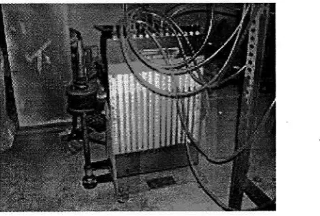
The pressure measuement for the CFB loop was done using the multi tube manometer. All the prcssue taps fed to multi tube manometer tubes. The prcssure tap through the riser wall had a copper tub€ inserted into it. Typical arangement for the pressure m€asuring system is shown in Figure 5 .
Figure 5: Pr€ssure measurement using multitube manometer
The axial profile for particle distribution in a CFB riser is typically composed of five sections: the acceleration, developed bottom-dense, ttansition, top-dilute and exit sections. Usually, the acceleration and developed bottom-dense sections arc together termed the bottom-dense (lower dense) section. In the studies ofthe axial particle distribution, many authors [10, 1 1,12, 13,14,15,161h^ve
^ssumed that the pressure gradient al an axial position is proportional to the amount ofsolid at that position.
Commonly used names for the region of large solids volume fraction are dense region, bottom bed and choked bed. The transition zone is frequently referred to as the acceleration, splash or developing flow region. The r€gion of low solids volume fraction is known as the dilute, transport or fully developed flow region. It is being shown in Figure 6 .
The experimental observation had led to the understanding that the riser flow is generally characterized by: (i) an nonlinear, axial solids volume fraction profile, (ii) upward solids motion in the core ofthe riser and downward motion along the walls (Core/Annulus, or C/A flow), and (iii) a tendency of solids to form clusters
Park F7] suggests
a new hydrodynamic mode; to represent
the gas flow in
fluidized Group A powders. The rnodel views that the paxticles form clusters
of inter-particle forces, giving rise to the formation of a heterogeneous
void
of clusters
of paxticles
and interstitial
cavities
the dense
phase
of
under the influence
stluctule conslstng
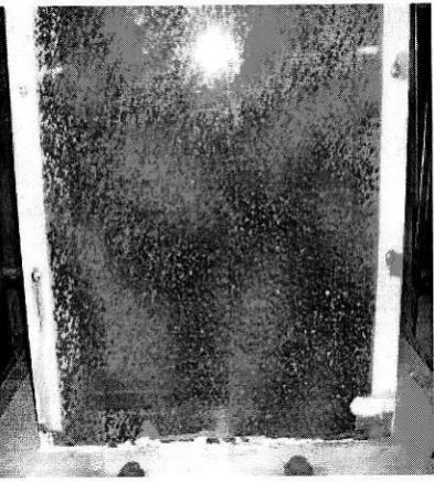
Figure 6: Fluidization behaviour for 600 pm palm shell waste particles
The expedmental results, suggest that riser flow is characterized by continuous formation and disintegration of clusters, and that clusters come in a va ety of shapes, sizes, velocities and solids volume fractions. In the acceleration and dilute region, the number and size ofclusters appear to increas€ towards the wall and be manimum near corners. Core clusters may move upwards or downwards, whereas wall clusters generally move downwards The number of clusters decreases with increasing elevation, especially near the cent€ ofthe cross-section. Th€ cluster size near the wall decreases with increasing elevation. Fluidization behaviour for the 1180 pm palm shell powder is being shown in Figure 7.
Figure 7: Fluidization behaviour fol I180 !m palrn shell waste particles
Visual obseNations by ofthe flow in the ds€r exit, suggest dunes of significant size in the riser exit connector. lt app€ars that solids in the hodzontal connector may settle under gravity, which
Intemational Eneqy Conference, Jakarta 5-7 Aug st 2005
means that the rcmainder ofthe suspension is accelerated Acceleration leads to a higher solids velocity in the cyclone and improves its €fficiency Similar findings have also been reported by f t 8 t .
Although the distinction between solids turbulence' and 'gas turbulenc€'may be primarily of interesito simulations, it seems reasonable to conclude that full understanding of fast fluidization cannot be obtained without considering turbul€nc€. It seems likely that an interacfi.jn hetwe€n collisions and turbulence is responsible for the macroscopic flow pattem
An interaction between turbulence and collisions seems consistenl with observations of a continuous formation and disintegration ofclusters Clusters may uphold a degree of stability against turbulence and coliisions, b€cause they experience less drag than individual particles ln addition, reduc€d drag increases the slip velocity and allows clusters to collect particles and grow in size,
RESIJLTS AND DISSCUSSIONS ON I\UMERICAL SIMIJLATIONS
Riser exits can affect the gross behaviour of a CFB. If more solids accumulate near the riser exit then fewer solids reside in the retum leg. The lower mte ofsolids circulation may cause the solids volume fraction in the riser and connector to be lower. However, ifthe solids accumulation near the ser€xit extends into these components, the solids volume fraction may be larger'
lnward/outward motion, secondary flows ofthe first kind, tang€ntial acceleration/deceleration, and cavity formation near riser exits is mechanisms can account for asymmetric flovr' in the exit region.
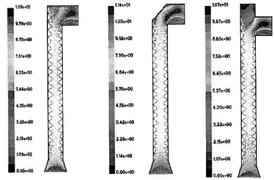
A right angle exit with intemal baflle and a blind T riser exits show that the solids volume fraction is more or less constant in the lower half of the riser. In the upper half, a stong increase ofsolids volume fraction with elevation was obs€rved for the blind T exit, wh€reas a decrease is found for the right angle exit with the intemal baIfle. The size and shape ofthe upsteam exit region is strongly dependent on the design of the riser exit. This is being shown in Figure 8
Figure 8: Contours ofvelocity using volume fraction of air
l l
The right angle exit accumulated more solids than the long radius ben'l exit The hlind T exit accumulated more solids trran tne rrgnt angie exit, and yieided a higher solids volum€ fraction in
ilil;;.
il;;itd,;oia-up
l. g."ui"'to'ihe exit with baffle The
blind r exits
shows
larger
,iila,
".ft."L""ai""s
along tlie entire riser height' and an increase of solids volume fraction *';i'fr
"f"t",.. i" itt" tpper hllfofthe riser' This-is
beingshown in Figure 9 The effectofan increase in H. appeared to b€ small
The solials volume fraction rcmarns con$ant near the exit with int€mal bame' but show an increase with "f"r"f".i" ift" tpp* ftalf of the riser for the right angle exit and blind
T €xit'
Figue 9: Contours ofvelocity by volume raction of solid particles
The disengag€ment exit anal the exit with internal bame invoke an upstream exit region of reduced solids ".i.r" d"ti"t. rrti" Uend exit yields little or no upstream
exit region The right angle exit' blind T exit ""4 ;i" *f,ft inlet or outlet baffle cause
an upstream exit region of increased solids volume fraction as shown in Figure l0 Larger blind T extension heights may invoke a greater upstream "l<iil"gli", "" f""J". iirey remain ielow a critical extension
height Medium size inl€t or outlet iuin.i.uv vi"ta lreater upstream exit regions than larBe or small baffles
l:
i:
x:
x:
t:
t:
t--t-
t'*
lI
,::x"*
l:
t,:
1:
t:
I
',*'t*
I
r-tist,,*
t:
Figwe l0: Contours of velociry by volume raction ofair
lntemational Energy Confercnce, Jakana 5-7 August 2005
Referring to the Figure 4, which shows a particle in the middle of a bend exit, which experi€nces a radial acceleration (utlR) equal to the radial component ofthe acceleration due to gravity (g cos45'or I /v5 ), i.e. llrn: g /Jt. This condition suggests that radial slip is minimized around
F\= llJt. Laryer valu€s of FrR may yield more movement of solids to the outside ofthe riser €xit ('outward' movement), and smaller Froude numbers more movement to the inside of the riser
Figure I l: Contours ofslip velocity
A radial acceleration balance suggests that inward/outward movement of solids in a riser exit is minimized around a Froude number F,"= Il aE . Larger lalues of FrR yield more mov€ment to the outside of the riser exit and smaller values more movement to the inside of the riser exit. From Figur€ 6 we can see that averag€ exit velocity in the right angle exit bend is about 10 m/s which results in FrR much abov€ the 1/at. So the predominant movement ofthe particles is outside of the riser exit. The same trend is also visible for other exits. However, the right angle exit with baffle show more pronounced movement outside the riser exit lt looks that Blind T has little effect ofthe extension height as compared to right angle exit. Figure ll suggests that the slip is more promin€nt in the exit bends. The slip distribution in the various exits are differ€nt with right angle exit and with baffle showing greater slip than blind T exit
CONCLUSIONS
All the above investigations suggest that ser exits can reduce solids hold-up in the riser and yield a region upstream wher€ the solids volume fraction decreases with elevation. Riser exits yi€ld an apparently onaffected solids volume fraction profile or increased solids hold-up and invoke a region where the solids volume fraction increases with elevation. This is evident also from expe mental observations
This suggests an upstream exit region to be defined as the region uPstream ofthe riser exit where flow properties arc affected by the riser exit. Similarly, a downstrearn exit region can be defined as the region downstream ofthe riser exit where flow properties are affected by the riser exit. The (overall) €xit region is th€ region ofthe CFB where flow properties are affected by the riser exit, and comprises the upstream exit region, do$,istream exit region and the ser €xit its€li
Th€ results suggest that (i) the right angle exit and the right angle exit with intemal baffle invoke an upstream exit region ofrcduced solids volume ftaction, (ii) the bend exit yields liftle or no upstream exit region, and (iii) the right angle exit, blind T exit and exits with inlet or outlet baffle cause an upstream exit resion ofincreased solids volume fraction.
Intemational Energy Conference, Jakarta 5-? August 2005
Th€ upstream exit rcgion is genemlly characteriz€d by a Cor€/Annulus structure, but that the solids mass flux profile may be asynrmetric. Some dser exits appear to invoke regions near the riser wall where solids motion is upwards.
ACKNOWI,DDGEMENT
The authors would lile to tlBnk Malaysian Govenment Cornrnonwealth Secretariat, Public Seffice
Deparhnent Malaysia, Putrajaya for funding the PhD program. Thanks are also due to Uni\"€rsiti Teknologi Malaysia lor providing financial supports for developing and building th€ CFB test facilily in the
Deparhnent ofMechanical Engineering, UTM, Sludai, Johor, Malaysia. RXFERENCNS
[1] cilbertson, M.A. and Yates, J.G. (1996). The Motion ofParticles Near a Bubble in a Gas-Fluidized Bed. Joumal of Fluid Mechanics 3231 317'385
[2] Pain, C.C., Mansoorzadeh, S. & de Oliveira, C.R.E. (2001). A Study of Bubbling and Slugging Fluidized Beds Using the Two-Fluid Granular Tempemtue Model lnternational Journal oJ Multiphase Floh' 2'7 , 527 -55l.
[3] Taghipour, F., Ellis, N. & Cla]ton, W. (2003). CFD Modeling ofa two-dimensional Fluidized Bed R€actor, Unive$ity of British ColumbD.
L4l Jalil R., Tasirin S. & M. S. Takiff (2002). l4]Computational Fluid D].namics (CFD) in Fluidized Bed colunm: effect of Internal Baffles, The proceedings ofRSCE Oct 2002, Malaysia.
[5] Hansen, K. G., Madsen, J., Ibsen, C. H., Solberg T. & Hjertager B H (2002). An expedmenial and computational study of a gas-particle flow in a scaled circulating fluidizedbed llorld Congtess on Particle Technolog), Edney, NW, Australia.
[6] Arastoopour, H., Benyahia, S., Knowlton, T. M. & Massah H. (2004) Simulation ofparticle and gas flow behavior in the riser section of a circulating fluidized bed using kinetic theory approach for the parti{JtTate ph^se. Pov,iler Techholo gt (Articlat i Pres s).
[7] Fluent 6.1, (2001). User's guide. Fluent Incorporated.
[8] Weinstein, H, H.J. Feindt, L. Chen, R.A. Graff(1992). The measur€ment ofturbulence quantities in a high velocity fluidized bed. Proceedings of 7- Ihter ational Conferc ce o FluidizLtion, O.E. Potter, D.J. Nicklin (eds), Engineering Foundation, NY, 305 - 312.
[9] Wu, S, M. Alliston (1993). Cold model testing of the effects ofair proportions and reactor outlet geometry on solids behaviour in a CFB, hoc€edings of l2s Intemational Conf€rence on Fluidized Bed Combustion, L.N. Rubow, G. Commotwealth (Eds.), ASME, 1003 - 1009.
uOl Xu, G. and Shiqiu, G. Necessary param€ters for specifying the hydrodlnarnics of circulating fluidizcd bed risers a review and rciteration. Powder Tecbnology 137,63-76,2003.
[l1] Davidson, J.F. Circulating Fluidized bed hydrodynamics. Chemical Engineering Science 113,249-260,2000.
Ioternaoooai Energy CoDference. Jakada 5-7 Augusr 2005
[12] Contractor, R., Dry R.J., White C., Mao Q.M., Konst rtinidis S and Potter O E. Circulaling fluidized beds-diameter, solid hold up, axial gas mixing and contact €fficiency. Powder Technology lllt 132-144,2000.
[13] Mandal, S., D. K. Achafee and P. S. Gupta. Distibution ofAxial Voidage in the riser oia Circulating Bed. Indian Joumal ofchemical Technology, Vol. 2, January 1995.
L14l Weinst€in, I{., L. Chen, and A. Kostazos. The Radial Pressure Gradi€nt in a Fluidized Beds Risers. Fluidization and Fluid-Particle Systems, AIChE Annual Meeting, 1995.
[l5] Van der Ham, A. G. J., W. Prias and W. P. M. van Swaat. Hydrod)'namics of a Pilot Plant Scale Regularly Packed Circulating Fluidized Bed. Fluid-Paficle Processes: Funalam€ntals and
Applications, AIChE Symposium Series, 1993.
[16] Yerushalmi, J. An Overyiew of Commercial Circulating Fluidized Bed Boilers. Circulating Fluidized Bed Technology II, 1985.
[t 7] Pa*, J.Y. The clustered dense phase models for goup A fluidization: Dense phase hydrod]'namics. Chemical Engineering Science, Vol. 58: 193-202,2003.
[18] Muschelknautz, E, U. Muschelknautz. Special design ofshort ent@ce ducts to recirculating cyclones. Proc. 5th Int. Conf. Circ. Fl. Bed, preFint volume, Eq6 I -6, 1996.
International Energy Conference, Jakarta 5-7 Au$at 2005