Elastocapillary deformations on partially-wetting
substrates: rival contact-line models
†
Joshua B. Bostwick,*aMichael Shearerband Karen E. Danielsc
A partially-wetting liquid can deform the underlying elastic substrate upon which it rests. This situation requires the development of theoretical models to describe the wetting forces imparted by the drop onto the solid substrate, particularly those at the contact-line. We construct a general solution using a displacement potential function for the elastic deformations within afinite elastic substrate associated with these wetting forces, and compare the results for several different contact-line models. Our work incorporates internal contributions to the surface stress from both liquid/solidSlsandSsgsolid/gas solid surface tensions (surface stress), which results in a non-standard boundary-value problem that we solve using a dual integral equation. We compare our results to relevant experiments and conclude that the generalization of solid surface tensionSlssSsgis an essential feature in any model of partial-wetting. The comparisons also allow us to systematically eliminate some proposed contact-line models.
1
Introduction
The deformation induced by a drop of liquid resting on an elastic substrate has been studied for some time.1–3Describing
such deformations has led to the development of theeld of elastocapillarity, in which elastic stresses are coupled to surface tension (capillary forces). Among the many biological, medical and industrial applications that involve the interaction of so substrates withuid interfaces4are enhanced condensation on
sosubstrates5and adhesion by liquid bridges.6Despite much
progress motivated by specic applications, a fundamental characterization of how a liquid wets a soelastic solid remains elusive.
In problems coupling elasticity to capillarity, the wetting properties of the substrate strongly control the material response. For a liquid on a hard substrate, these wetting prop-erties are dened by the Young–Dupr´e equation,7,8
ssgsls¼scosa, (1)
which relates the liquid/gass, liquid/solidslsand solid/gasssg
surface tensions to the static contact-anglea. Fig. 1 illustrates the interpretation of the Young–Dupr´e relationship as a hori-zontal force balance. Note that this formulation leads to an imbalance of forces normal to the solid substrate with
magnitudeFCL
t ¼ssina. The classical model of wetting of so
substrates includes this normal contact-line force applied as a point load at the contact-line, as well as the capillary pressure p ¼ 2ssina/R uniformly distributed along the liquid/solid surface area, as shown in Fig. 2. More recently, alternative models of wetting have been proposed to properly account for intrinsic surface stresses in the elastic substrate and to distin-guish surface stress from surface energy.9,10For these models,
thermodynamics dictates that the surface stressSis related to the surface energysby the Shuttleworth equation,SAB¼sAB+ vsAB/v3with3the bulk strain parallel to the interface, reecting
an energetic penalty for deformation.11Here A, B represent the
phases on either side of the interface. For substrates with an incompressible surface layer, the surface stressSis equal to the surface energysand both can be referred to as surface tension (Weijset al.10). Herein, we refer to
sABas the surface tension and SABas the solid surface tension. The result of the new models is
to augment the classical model with a contact-line force FCLk parallel to the solid and directed into the liquid phase.
In this paper we formulate a general model that describes the deformations of an elastic substrate by a partially-wetting liquid drop. The general model, formulated in terms of a displacement potential function, accommodates three rival
Fig. 1 The Young–Dupr´e eqn (1) schematically as a horizontal force balance.
aDepartment of Engineering Science and Applied Mathematics, Northwestern
University, Evanston, IL 60208, USA. E-mail: [email protected]
bDepartment of Mathematics, North Carolina State University, Raleigh, NC 27695,
USA
cDepartment of Physics, North Carolina State University, Raleigh, NC 27695, USA †Electronic supplementary information (ESI) available. See DOI: 10.1039/c4ra03286a
Cite this:DOI: 10.1039/c4sm00891j
Received 24th April 2014 Accepted 7th July 2014
DOI: 10.1039/c4sm00891j
www.rsc.org/softmatter
PAPER
Published on 31 July 2014. Downloaded by North Carolina State University on 31/07/2014 14:26:27.
contact-line models. By introducing both liquid/solidSls and
solid/gasSsgsolid surface tensions, we generalize the work of
Style and Dufresne12on neutrally-wetting substrates (
a¼90) to partially-wetting substrates (a s 90). This leads to a force boundary condition at the substrate surface that varies along the problem domain. We construct a solution to this non-standard problem by setting up a dual integral equation that results from extending the boundary condition into the complementary interval. We compare computed displacement
elds from the general model to experimental results. The markedly different displacement elds predicted by the different models eliminates one model, and suggests suitable experiments to further resolve which of the others are most plausible.
Elastocapillary phenomena generally become important when the liquid surface tensionsand the elastic resistance of the solid substrate have similar magnitude, as measured by the elastocapillary numberY¼s/EL. HereEis the elastic modulus of the substrate andLis a characteristic length scale. For most liquids of interests¼ 10–100 mN m1, and to adjustYit is typically easier to changeLorE. Experiments on the wrinkling of elastic sheets13–16and capillary origami17use smallL. Using
silicone gel,18,19 gelatin20,21 or agar gel22 as a solid substrate
allowsEto be controllably tuned over several orders of magni-tude. In systems without an intrinsic length scale, the elasto-capillary length‘¼s/Esets the size of the elastic deformation. For reference, water (s¼72 mN m1) on a silicone gel substrate
(E¼3 kPa) yields deformations of order ‘ 106m. This is
distinct from thin solids, such as those utilized in capillary origami experiments, where an alternative elastocapillary lengthpffiffiffiffiffiffiffiffiB=scan be dened using the bending modulusBas a measure of the elastic resistance.
Many of the relevant experimental studies mentioned above involve neutrally-wetting (a ¼ 90) substrates.13,18 Studies of
partial-wetting generally involve adding surfactant to the liquid to adjust the liquid/gas surface tension. Schrollet al.16study
how the wrinkling of ultra-thin elastic sheets due to a droplet is affected by the presence of a liquid bath covered in a pre-determined surfactant concentration. They derive near-threshold and far-from-near-threshold limits that recover experi-mental observations. Danielset al.22have shown that a droplet
of surfactant-laden liquid placed on an agar gel can fracture the substrate in a starburst pattern. The number of arms in a given starburst is controlled by the surface tension contrastssgs,
an alternative measure of the degree to which a liquid partially wets a sosolid. Bostwick and Daniels23developed a model to
predict the number of arms for this situation, and have shown that the location of the contact-line, which depends uponaand the droplet volumeV, is the critical parameter in wavenumber selection, in agreement with experiments. Lastly, Style et al.24
study the contact mechanics of glass particles pressed into so materials. These results show thataobeys a generalized Young– Dupr´e equation when the indenting particle size is on the order of the elastocapillary length‘.
Theory of the spreading of liquids over compliant substrates naturally relies upon an appropriate characteriza-tion of the physics of wetting, in much the same way that traditional dynamic spreading laws for liquids on rigid solids25–27build upon the static Young–Dupr´e equation. For a
liquid spreading on a soviscoelastic substrate, Kajiyaet al.28
show that the liquid can move continuously or with stick-slip motion depending upon the ratio of the loss to storage modulus.29The motion of a liquid on a sosubstrate
expe-riences viscoelastic braking from the wetting ridge at the contact-line.30–32
Hence, a description of the deformationeld is needed to study the dynamics of spreading. Most of the existing theoret-ical models are only valid for neutrally-wetting (a ¼ 90) substrates12,18 or straight 2D contact-lines.33 Alternative
methods employ computational approaches such as density functional theory (DFT)34and molecular dynamic (MD)
simu-lations35to gain a more thorough understanding of the wetting
forces acting at the contact-line. The thrust of our work lies in the modeling of partially-wetting systems.
We begin by formulating a mathematical model (Section 2) for the deformation of an elastic substrate due to a partially-wetting liquid droplet. The effects of partial-partially-wetting appear in (i) the contact-line force boundary conditions and (ii) the solid surface tensionsSsgsSls. Three rival contact-line models are
introduced and the governing equations are recast using a displacement potential. We then construct a general solution of the dual integral equation that results from the disconti-nuity in solid surface tension S along the surface of the substrate. The discontinuity occurs where the interface changes from liquid/solid to solid/gas. Our numerical results are presented in Section 3, where we contrast measures of the elastic displacement eld for the different models as they depend upon the model parameters. Comparisons between the predicted elds and relevant experiments allow us to systematically eliminate some proposed contact-line models. In addition, we show that the generalization of solid surface tension is an important feature for modeling wetting on so substrates. We conclude with some remarks in Section 4 on Fig. 2 Definition sketch: a liquid droplet with contact-line radiusR
wetting an elastic substrate of heighth, elastic modulusEand Poisson rationand the associated wetting forces included in the model; the capillary pressurepand contact-line forceFCL.
future studies that could help resolve the issue of which model of wetting is most realistic.
2
Mathematical formulation
A partially-wetting droplet resting on a solid substrate is held by liquid–gas surface tensions at its free surface. For negligible gravitational forces, the equilibrium shape is a spherical-cap with contact-line radiusR, static contact-angleaand volume
V R3¼
p
3
ð23 cosaþcos3aÞ
sin3a : (2)
Note that forxed volume drops,Randaare not indepen-dent parameters. The linear elastic substrate has thickness h and is characterized by an elastic modulusEand Poisson ratio n, as shown in Fig. 2. The liquid interacts with the solid through both the capillary pressurep¼2ssina/Runiformly distributed over the liquid/solid contact area and the unbalanced contact-line forceFCLapplied at the contact-line radiusR(cf.Fig. 2). We
compute the elastic response in the substrate due to these wetting forces.
2.1 Field equations
We begin by introducing the axisymmetric displacementeldu,
u¼ur(r,z)ˆer+uz(r,z)ˆez, (3)
in cylindrical coordinates (r,z), which satises the governing elastostatic Navier equations,
(12n)V2u+V(V$u)¼0. (4)
The straineld3is dened as
3¼1
2
Vuþ ðVuÞt;
(5)
while the stresseldsijfor this linear elastic solid is given by
sij¼ E
1þn
3ijþ n
12n3kk
: (6)
2.2 Boundary conditions
We assume the elastic substrate is pinned to a rigid support atz
¼0 by enforcing a zero displacement boundary condition there,
u(r, 0)¼0. (7)
On the free surfacez¼h, we specify the surface tractions
srzðr;hÞ ¼FrðrÞ; 0#r#N;
szzðr;hÞ SlsVk2uzðr;hÞ ¼FzðrÞ; 0#r#R;
szzðr;hÞ SsgVk2uzðr;hÞ ¼FzðrÞ; R\r#N:
(8)
here Vk2 is the surface Laplacian andFz(r) and Fr(r) are the
applied vertical and horizontal forces associated with the liquid/solid interactions. These forces are model-dependent, and their particular choice will be discussed in Section 2.3. As
discussed by Style and Dufresne,12Jerisonet al.,18introducing
the S solid surface tension (i) allows for the modeling of neutrally-wetting substratesSsg¼Sls(a¼90) and (ii)
regular-izes the singularity associated with applying ad-function force to the medium's surface. Here, we extend this technique to allow us to model partially-wetting substrates with Ssgs Sls
corresponding toas90.
2.3 Wetting forces
We now develop a model for the forcesFz,Frassociated with the
wetting of a liquid droplet on a so elastic substrate. For a liquid droplet held by uniform surface tension s, the vertical wetting forces are given by
FzðrÞ ¼ssina
dðrRÞ R2HðRrÞ
: (9)
here the capillary pressure p ¼ 2ssina/R (second term) is uniformly distributed over the liquid/solid surface area by the Heaviside functionH(Rr), whereas the unbalanced vertical contact-line forceFCL
z ¼ssina(rst term) is applied as a point
load using a delta functiond(r R) at the contact-liner¼R. Note the orientation of the applied forces; the capillary pressure p compresses the substrate, while the contact-line force FCLz
tends to pull the substrate upwards. In fact, the upward contact-line force precisely balances the net downward force from the pressure. Eqn (9) is the standard, or classic, description of wetting of sosubstrates.
More recent models of wetting have introduced an uncom-pensated parallel contact-line force Fr(r), in addition to the
vertical wetting forces (9) described above.10,34Here we would
like to construct a general solution for the models of wetting discussed below in order to contrast the resulting elasticelds. Each model for the uncompensated parallel contact-line force can be written as
Fr(r)¼FCLr d(rR) (10)
with the coefficient FCLr for the respective model shown in
Table 1.
2.4 Summary of wetting models
Model I corresponds to the classic picture of wetting in which the contact line exerts no horizontal force on the substrate. In contrast, Models II and III take the same form with respect toa,
Table 1 Horizontal contact-line forceFCL
r for the classic description of
wetting (I), used by Jerisonet al.,18Style and Dufresne,12and updated Models II and III, proposed by Daset al.34and Weijset al.,10respectively. Heresis the surface tension,nthe Poisson ratio, andathe contact angle given by eqn (1)
Model FCLr
I 0
II s(1 + cosa)
III
sð1þcosaÞ
12n
1n
but have different dependence on the Poisson ratio n of the substrate. Note that for the unusual case ofn¼ 0, Model III reduces to Model II; however, ordinary materials do not typi-cally reach this limit.36 The more interesting case is that of
incompressible substrates, for which n ¼ 1/2 and Model III reduces to Model I. Many somaterials are known to be highly incompressible37 and modern measurement techniques38 are
making it possible to obtain precise values of the deviation from 1/2. In particular, the experiments of Style et al.24report
n ¼ 0.495 for the silicone gel to which we compare model results below. Even if Model III were the correct model, the closeness to n¼1/2 would explain why Model I has been so successful in predicting the elastic deformations on sosubstrates.
2.5 Displacement potential—Love function
The Navier eqn (4) are simplied by introducing the Galerkin vectorG,39dened such that
u¼1þEn2ð1nÞV2GVðV$GÞ (11)
with
G¼x(r,z)ˆez. (12)
Sometimes the potentialxis referred to as the Love function from classical linear elasticity. We substitute (11) into the coupled system of differential eqn (4) to show thatxsatises the biharmonic equation
V4
x¼0. (13)
The displacement (7) and traction (8) boundary conditions can similarly be written in terms of the potential functionx.
2.6 Hankel transform
We seek solutions to (13) for the potential function using the Hankel transform pair,
^ xðs;zÞ ¼
ðN
0
rxðr;zÞJ0ðsrÞdr; (14a)
xðr;zÞ ¼ ðN
0
s^xðs;zÞJ0ðsrÞds; (14b)
whereJ0is the Bessel function of therst kind andsis the radial
wavenumber.
2.7 Reduced equations
We introduce the following dimensionless variables;
uhu~Es; rh~rh; zh~zh; sh~sh; RhRh~ : (15)
here lengths are scaled by the thickness of the elastic substrate hand elastic deformations by the elastocapillary length‘hs/E. Herein we drop the tildes for notational simplicity. Substituting the Hankel expansion (14a) into (13) gives a reduced equation for^x,
V4^ x¼
d2 dz2s
2 2
^x¼0; (16)
combined with the no-displacement condition on the rigid supportz¼0,
d^x
dz¼0;ð12nÞ d2^
x
dz22ð1nÞs 2^
x¼0: (17)
The general solution of (16) and (17) is given by
^x¼CcoshðszÞ þszsinhðszÞ 2ð12nÞ
þDðszcoshðszÞ sinhðszÞÞ;
(18)
with the constants C, D to be determined from the traction boundary conditions (8). Here we note that the form of (8) is not amenable to standard analysis because the vertical boundary conditionsszzchange along the problem domainr˛[0,N]. We
address this issue in the following section by constructing a solution to this non-standard problem using a dual integral formulation. Given the solution^x, we computexin real space by evaluating the inverse Hankel transform (14b). Once the potential functionxis known, the displacementu, strain3and stressselds are obtainedviasubstitution into (11), (5) and (6), respectively.
2.8 Dimensionless groups
The following dimensionless groups arise naturally from the choice of scaling (15),
YhEhs;YsghS sg
Eh;YlshS ls
Eh;Lh R
h: (19)
HereY,YsgandYlsare the liquid/gas, solid/gas and liquid/solid
elastocapillary numbers and L is the aspect ratio or dimen-sionless contact-line radius. We also dene the solid surface tension contrast DY h Ysg Yls, which can be viewed as a
measure of partial wetting.
2.9 Dual integral equation
The vertical componentszz of the traction boundary
condi-tions (8) changes along the problem domain depending upon whether the solid substrate interacts with the liquid droplet (r ˛ [0, R]) or the passive gas (r ˛ [R, N]). To specify the constants C, D in our general solution (18), we recast the traction boundary conditions (8) in a form amenable to a dual integral solution,
srz¼Fr(r), 0#r#N (20a)
szzSsgVk2uzFz(r)¼(SlsSsg)Vk2uz, 0#r#R (20b)
szzSsgVk2uzFz(r)¼0,R<r#N (20c)
The vertical force balance (20b) and (20c) is then written as ðN
0
AðsÞJ0ðsrÞds¼ GðrÞ
0#r#R
0 R\r#N (21)
with
AðsÞ ¼s^szzþSsgs2uz^ F^z
;GðrÞ ¼DS ðN
0
s3uzJ^
0ðsrÞds; (22)
andDShSsgSls. Eqn (21) is recognized as a dual integral
equation with a standard solution,40,41
AðsÞ ¼p2
ðR
0
cosst
ðR
t
rGffiffiffiffiffiffiffiffiffiffiffiffiffiðrÞ
r2t2
p drdt: (23)
Note that the solution is valid over the full domainr˛[0,N]. Substituting ((18) and (22)) into (23) yields
s(^tzz+Ssgs2ˆuzF^z)¼CA1(s) +DA2(s), (24)
where
AkðsÞ ¼DSp2 ðR
0
cosst
ðR
0
r ffiffiffiffiffiffiffiffiffiffiffiffiffi r2t2
p ðN
0
q3vkðqÞJ
0ðqrÞdqdrdt; (25)
and
v1ðqÞ ¼
q3sinhq
2ð12nÞ; (26a)
v2ðqÞ ¼q2
2ð310nþ8n2Þsinhq2qð12 nÞcoshq
2ð12nÞ : (26b)
Eqn (24) and the Hankel-transformed horizontal force balance (20a) are a linear system of equations forC,D, whose solution is given in the Appendix.
3
Results
Our goal is to contrast the three contact-line models and the interpretation of solid surface tension for partial wetting, by comparing theoretical displacement elds to relevant experi-ments. Some of these comparisons can be directly evaluated using data from the literature, while others identify tests which would help design future experiments. We compute the elastic
elds by substituting the coefficientsC,Dinto (12) and evalu-ating (14b) for the displacement potential, from which the displacementsu, strains3and stressessare readily obtained. These solutions provide quantitative measures of how the elasticeld, for instance the vertical contact-line displacement uCLz (peak height), varies with the model parameters.
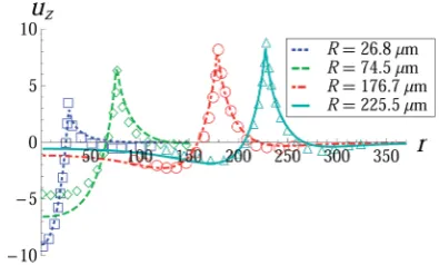
We begin by comparing our model to the experimental results of Styleet al.,19who use confocal microscopy to measure
surface displacements on silicone gels from partially-wetting droplets. Their focus is in how the displacementelds vary with two length scales, the contact-line radiusRand substrate height h. Fig. 3 shows how the vertical surface displacementuzchanges
across the substrate for Model I. Material parameters for our computations are taken directly from the reported values.19
Note thatnz1/2 for silicone gels, which implies that contact-line Models I and III are equivalent for these experiments. We see that our model is able to adequately reproduce the experi-mental results over a range of contact-line radii, which is
achieved experimentally by varying the droplet volume while holding the other parametersxed. The capillary pressurep¼ 2ssina/Rtends to compress the material beneath the drop and is more pronounced for smaller drops, as would be expected. For larger dropsR¼225.5mm (solid line type), the contact-line force dominates the elastic response and the compressive troughs on either side of the contact-line peak become nearly symmetrical, reecting a nearly two-dimensional solution.18
Despite the large variation in surface prole with droplet size, the local geometry of the wetting ridge remains invariant; the predicted microscopic contact angle 93.8for both contact-line Models I and II agrees well with that reported by Styleet al.19(cf.
ESI, Fig. S5†). We attribute this observation to the generaliza-tion of solid surface tension.
The peak heightuCLz directly at the contact-line can be used
as a measure of the elastic response of the underlying substrate. In Fig. 4, we plot the peak height for Models I and III as a function of the contact-line radius R for various substrate heights h, and compare with experiments on silicone gel substrates.19 For a xed substrate height h, the peak height
increases with increasing contact-line radius R, achieves a Fig. 3 Comparison with Styleet al.,19Fig. 1. Surface displacementu
z
on ah¼50mm thick substrate againstrfrom Model I, III, as it depends upon the contact-line radiusRforn¼0.5,Ysg¼0.207,DY¼ 0.033,E
¼3 kPa,s¼46 mN m1and
a¼95. Lengths are reported inmm. Experimental results are shown with open symbols. Material properties are taken to be those reported in the experiments.19
Fig. 4 Comparison with Styleet al.,19Fig. 3. Contact-line displacement
uCL
z computed from Model I, III against drop radiusR, as it depends
upon the substrate heighthforn¼0.5,Ysg¼0.207,DY¼ 0.033,E¼ 3 kPa,s¼ 46 mN m1and
a¼ 95. Lengths are reported in mm. Experimental results are shown with open symbols.
maximum and decreases thereaer. Smaller substrate heights lead to uniformly smaller peak heights reecting the presence of the underlying rigid support, where the zero displacement condition (7) is enforced. In contrast, thicker substrates are less affected by the underlying support since there is more material to resist the applied surface tractions, resulting in larger peak deformations. Fig. 4 demonstrates the non-monotonic depen-dence on contact-line radius, consistent with experiments. We attribute this behavior to the effects of partial wetting (a¼95) that result from a non-trivial difference between the liquid/solid and solid/gas solid surface tensionsDYs0.
For neutrally-wettinga¼90substrates (DY¼0), the peak height is a monotonic function of the contact-line radiusLfor Models I, III, as shown in Fig. 5. That is, the peak height increases with the contact-line radius and then plateaus. We conclude that the generalization which differentiates between theSlsandSsgsolid surface tensions is a feature of the model
that is required to reproduce the experimental data. In contrast, Fig. 5 shows that for Model II withDY¼0, the peak height is a non-monotonic function of the contact-line radius that is also consistent with experiments (cf.Fig. 4).
We proceed by contrasting contact-line Models I, III and II on incompressible (n¼1/2) substrates. Fig. 6 plots the surface displacementsuz,urfor Models I and II on a neutrally wetting
a¼90substrate. The peak heightsuCLz are supercially similar,
but theelds vary greatly away from the contact-line. Notice that beneath the drop the eld is compressive for Model I and tensile for Model II. Outside the drop, the compressive dimple is much more pronounced for Model II. Fig. 7 compares surface proles foruorinert drops with a¼ 40 against experiment demonstrating that Model I more accurately captures the experimental observations. Additional comparisons to experi-ment are given in the Suppleexperi-mentary Material. A more dramatic difference between Model I and II is seen in the radial surface
displacement. For Model I, there is a peak on the droplet side and a trough on the gas side of the contact-line that eventually becomes symmetric as the contact-line radius increases. In contrast, the radial displacement is directed into the drop (ur<
0) for Model II. In addition to the qualitative differences in the radial displacementeld, note the radial displacementurscale
changes by an order of magnitude between Models I and II. This observation is robust and occurs over a large range of parame-ters (cf.ESI†). Such a dramatic effect should clearly be visible in
experiment. However, Jerisonet al.,18Fig. 2 measure the radial
displacement eld on incompressible silicone gel substrates showing aeld more similar to that of Model I than Model II. We conclude that contact-line Model II does not accurately capture the existing experimental data and, hence, rule it out as a candidate contact-line law.
At this point, our candidate models have been reduced to either Model I or Model III. We have demonstrated above that the generalization of solid surface tensions (DY s 0) is an essential feature of any model. Recall that Model III includes a horizontal force that depends upon the Poisson ration, which
Fig. 5 Contact-line displacement comparing Models I, III and II by plotting the axialuCL
z and radialuCLr displacement at the
contact-line (r¼L), as it depends upon the solid elastocapillary number Y¼Ysg¼Ylsand the contact-line radiusLforn¼1/2 anda¼90.
Fig. 6 Comparison between Models I, III and II by plotting the surface displacementsuz,uron an incompressiblen¼1/2 substrate, againstr,
as it depends upon the contact-line radiusL, forYls¼1,Ysg¼1,a¼ 90+. Note the different scales for the radial displacement.
Fig. 7 Surface displacementuzfor afluorinert drop on ah¼23mm
thick substrate againstrcomparing Models I, III to Model II, forR¼ 196.59mm,n¼0.5,Ysg¼0.349,DY¼0.149,E¼3 kPa,s¼17 mN m1 and a ¼ 40. Experimental results are shown with open symbols. Lengths are reported inmm. Material properties are taken to be those reported in the experiments.19
degenerates into Model I when n ¼ 1/2. Fig. 8 shows the displacementelds for Model III, as they depend upon nfor nearly incompressible substrates. For the vertical displacement uz, the peak height does not appreciably change withn, while
the largest difference occurs near the center of the dropr¼0. The most dramatic difference occurs for the radial displace-mentur, where the presence of the horizontal force dominates
the elastic response, even atn¼0.45 and more so asndecreases from 1/2. With regards to validation of the models, most experiments utilize nearly incompressible materials and, as we have stated, one cannot differentiate between Models I and III in this limit. Experimental measurements of the radial displacementeld on compressible substrates should resolve this issue once and for all.
A typical measure of the elastic response due to a partially-wetting liquid is the contact-line displacement, which can usually be measured without sophisticated diagnostics. Another benet is that the contact-line displacement is a scalar measure of the more complicated elastic eld. Fig. 9 shows how the
contact-line displacement for a neutrally-wetting (a ¼ 90) substrate varies with the Poisson rationand solid elastocapil-lary numberY for Models I, III. The information shown here could be used in future experiments to reconcile the appro-priate contact-line law, either Model I or III.
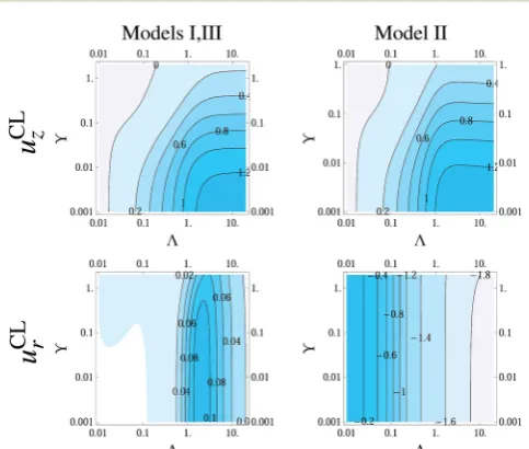
Finally, we show how the contact-line displacement varies with LandDYin Fig. 10. Note that for partially-wetting situations, both aandDYchange with the surface chemistry. Hence, we plot the displacementsusina. The contact-line displacement for Model II is given in the Supplementary Material. We view Fig. 10 as a guide for future studies on partially-wetting substrates.
4
Discussion
We have considered the elastic deformations of a sosubstrate due to the presence of a partially-wetting liquid. We construct a general solution for the displacement potential (Love function) comparing three rival contact-line models for wetting forces imparted by the liquid onto the solid. In addition, our model generalizes the concept of solid surface tension to partially-wetting substratesas90, whereSlssSsg. The result of which
is a non-standard boundary-value problem that we solve using a dual integral equation. The thrust of this work is that our general solution encompasses all current contact-line models, as well as the interpretation of solid surface tension as a surface stressShSsg¼Slsor surface energySsgsSls.
We compare the computed elastic displacement elds to relevant experiments,18,19which allows us to identify the most
likely model of wetting of so substrates from the potential candidate models. When comparing to experiment, we imme-diately see that the surface energy interpretationDYs0 is an essential feature that should be included in any model of partial-wetting. Contact-line Model II is ruled out as a candidate based upon the dramatic differences between the computed displacementeld and experimental observations. This leaves contact-line Models I and III as possibilities. However, since the relevant experiments involve incompressible substratesnz1/2, which also coincides with the degenerate limit between Models I and III, we are unable to identify the appropriate wetting law at this time. Instead, we use our solution to the general problem to show how measures of the elastic response vary with the Fig. 8 Compressibility effects from contact-line Model III withR ¼
74.5mm andR¼225.5mm: axialuzand radialurdisplacementfield in
mm, as it depends upon the Poisson ratio n, forYsg ¼0.207,DY¼
0.033,E¼3 kPa,s¼46 mN m1and
a¼95. Open symbols in left sub-figure are two experiments from Style and Dufresne.12
Fig. 9 Comparison of the axial uCL
z and radial uCLr contact-line
displacement for Models I and III, as it depends upon the Poisson ratio nand the contact-line radiusLforYhYsg¼Yls¼1 anda¼90.
Fig. 10 Comparison of the axialuCL
z sinaand radialuCL
r sina contact-line displacement for Models I and III, as it depends uponDYand the contact-line radiusLforn¼1/2 andYsg¼1.
relevant system parameters. The strategy is to use the theory to suggest experimental efforts to resolve this dispute, which is of practical importance in moving theeld forward.
Appendix: Computation of the
constants
C
,
D
The integrals Ak, dened in eqn (25), can be evaluated by
interchanging the order of integration with respect to drdt/ dtdrand making use of a Bessel function identity,
J0ðsrÞ ¼
2
p ðr
0
cosst
ffiffiffiffiffiffiffiffiffiffiffiffiffi r2t2
p dt; (27)
which yields
A1ðsÞ ¼DSR
s6sinhsJ 0ðsRÞ
2þJ 1ðsRÞ
2
4ð12nÞ (28)
A2ð Þ ¼s DS
1 2Rs
5J 0ðsRÞ
2þJ 1ðsRÞ
2
ðscoshsþ ð4n3ÞsinhsÞ:
(29)
Finally, we apply scalings (15) and simultaneously solve ((20a) and (24)) to give
CX(s)/(2(1 + 2n))¼2F^z(s)(scoshs+ (1 + 2n)sinhs) +F^r(s)(2ssinhs+ 4(1 +n)coshs +Ysg(s2(1 +n)coshs
+s(3 +n+ 4n2)sinhs) DYLs(1 +v)(scoshs + (3 + 4n)sinhs)(J0(sL)
2
+J1(sL) 2
)) (30)
DX(s)¼Fz^(s)(2ssinhs+ 4(1n)cosh s)
+Fr^(s)(2scoshs+ (24n+s2Ysg(1 +n) DYLs2(1 +n)(J0(sL)2
+J1(sL)2))sinhs) (31)
where
X(s)¼s3(5 + 2s2+ 4n(3 + 2n) + (34n)cosh2s +sYsg(1 +v2)(2s+ (3 + 4v)sinh2s) DYLs(1 +n2)(J0(sL)2+J1(sL)2)
(2s+ (3 + 4n)sinh 2s)), (32)
andDYhYsgYls. The applied forcesF^are given by
^
FzðsÞ ¼sina
LJ0ðsLÞ
2
sJ1ðsLÞ
;F^rðsÞ ¼FCL;rLJ1ðsLÞ;
(33)
with the coefficientFCL,rtaken from the models given in Table 1.
Acknowledgements
This work was supported by the National Science Foundation under grant number DMS-0968258. The authors thank Robert Style and Eric Dufresne for sharing their experimental data.
References
1 G. Lester,J. Colloid Sci., 1961,16, 315–326.
2 M. Shanahan and P.-G. De Gennes,C. R. Seances Acad. Sci., Ser. 2, 1986,302, 517–521.
3 M. E. R. Shanahan,J. Phys. D: Appl. Phys., 1987,20, 945. 4 B. Roman and J. Bico, J. Phys.: Condens. Matter, 2010,22,
493101.
5 M. Sokuler, G. K. Auernhammer, M. Roth, C. Liu, E. Bonacurrso and H.-J. Butt,Langmuir, 2009,26, 1544–1547. 6 J. S. Wexler, T. M. Heard and H. A. Stone,Phys. Rev. Lett.,
2014,112, 066102.
7 T. Young,Philos. Trans. R. Soc. London, 1805,95, 65–87. 8 A. Dupr´e,Th´eorie M´echanique de La Chaleur, Paris,
Gauthier-Villars, Paris, France, 1869, p. 369.
9 A. Marchand, S. Das, J. H. Snoeijer and B. Andreotti,Phys. Rev. Lett., 2012,109, 236101.
10 J. H. Weijs, J. H. Snoeijer and B. Andreotti,Phys. Rev. E: Stat., Nonlinear, SoMatter Phys., 2014,89, 042408.
11 R. Shuttleworth,Proc. Phys. Soc., London, Sect. A, 1950,63, 444.
12 R. W. Style and E. R. Dufresne,SoMatter, 2012,8, 7177– 7184.
13 J. Huang, M. Juszkiewicz, W. H. de Jeu, E. Cerda, T. Emrick, N. Menon and T. P. Russell,Science, 2007,317, 650–653. 14 D. Vella, M. Adda-Bedia and E. Cerda,SoMatter, 2010,6,
5778–5782.
15 B. Davidovitch, R. D. Schroll, D. Vella, M. Adda-Bedia and E. Cerda,Proc. Natl. Acad. Sci. U. S. A., 2011,108.
16 R. Schroll, M. Adda-Bedia, E. Cerda, J. Huang, N. Menon, T. Russell, K. Toga, D. Vella and B. Davidovitch,Phys. Rev. Lett., 2013,111, 014301.
17 S. Jung, P. M. Reis, J. James, C. Clanet and J. W. M. Bush, Phys. Fluids, 2009,21, 091110.
18 E. R. Jerison, Y. Xu, L. A. Wilen and E. R. Dufresne,Phys. Rev. Lett., 2011,106, 186103.
19 R. W. Style, R. Boltyanskiy, Y. Che, J. Wettlaufer, L. A. Wilen and E. R. Dufresne,Phys. Rev. Lett., 2013,110, 066103. 20 C. Spandagos, T. B. Goudoulas, P. F. Luckham and
O. K. Matar,Langmuir, 2012,28, 7197–7211.
21 C. Spandagos, T. B. Goudoulas, P. F. Luckham and O. K. Matar,Langmuir, 2012,28, 8017–8025.
22 K. E. Daniels, S. Mukhopadhyay, P. J. Houseworth and R. P. Behringer,Phys. Rev. Lett., 2007,99, 124501.
23 J. B. Bostwick and K. E. Daniels,Phys. Rev. E: Stat., Nonlinear, SoMatter Phys., 2013,88, 042410.
24 R. W. Style, C. Hyland, R. Boltyanskiy, J. S. Wettlaufer and E. R. Dufresne,Nat. Commun., 2013,4.
25 L. Tanner,J. Phys. D: Appl. Phys., 1979,12, 1473.
26 E. van Dussan,Annu. Rev. Fluid Mech., 1979,11, 371–400. 27 L. Hocking,J. Fluid Mech., 1992,239, 671–681.
28 T. Kajiya, A. Daerr, T. Narita, L. Royon, F. Lequeux and L. Limat,SoMatter, 2013,9, 454–461.
29 T. Kajiya, P. Brunet, A. Daerr, L. Royon, T. Narita, F. Lequeux and L. Limat, Interfacial Phenomena and Heat Transfer, 2013,1.
30 A. Leh, H. E. Nguessan, J. Fan, P. Bahadur, R. Tadmor and Y. Zhao,Langmuir, 2012,28, 5795–5801.
31 L. Chen, E. Bonaccurso and M. E. R. Shanahan,Langmuir, 2013,29, 1893–1898.
32 B. B. J. Stapelbroek, H. P. Jansen, E. S. Kooij, J. H. Snoeijer and A. Eddi,SoMatter, 2014,10, 2641–2648.
33 L. Limat,Eur. Phys. J. E: SoMatter Biol. Phys., 2012,35, 1–13. 34 S. Das, A. Marchand, B. Andreotti and J. H. Snoeijer,Phys.
Fluids, 2011,23, 072006.
35 J. H. Weijs, B. Andreotti and J. H. Snoeijer,SoMatter, 2013, 9, 8494–8503.
36 P. Mott and C. Roland,Phys. Scr., 2013,87, 055404. 37 J. Mark, Polymer Data Handbook, Oxford University Press,
Incorporated, 1999.
38 R. H. Pritchard, P. Lava, D. Debruyne and E. M. Terentjev, SoMatter, 2013,9, 6037–6045.
39 R. Soutas-Little,Elasticity, Dover Publications, 1999. 40 I. Sneddon, Mixed Boundary Value Problems in Potential
Theory, John Wiley & Sons, New York,NY, 1966.
41 N. Hoshan, Int. J. Contemp. Math. Sciences, 2009, 4, 1695– 1699.