University of Windsor University of Windsor
Scholarship at UWindsor
Scholarship at UWindsor
Electronic Theses and Dissertations Theses, Dissertations, and Major Papers
2016
Development of a Hydraulic Bulge Test to Determine the Work
Development of a Hydraulic Bulge Test to Determine the Work
Hardening Behaviour of Sheet Materials
Hardening Behaviour of Sheet Materials
Mario Vasilescu
University of Windsor
Follow this and additional works at: https://scholar.uwindsor.ca/etd
Recommended Citation Recommended Citation
Vasilescu, Mario, "Development of a Hydraulic Bulge Test to Determine the Work Hardening Behaviour of Sheet Materials" (2016). Electronic Theses and Dissertations. 5919.
https://scholar.uwindsor.ca/etd/5919
This online database contains the full-text of PhD dissertations and Masters’ theses of University of Windsor students from 1954 forward. These documents are made available for personal study and research purposes only, in accordance with the Canadian Copyright Act and the Creative Commons license—CC BY-NC-ND (Attribution, Non-Commercial, No Derivative Works). Under this license, works must always be attributed to the copyright holder (original author), cannot be used for any commercial purposes, and may not be altered. Any other use would require the permission of the copyright holder. Students may inquire about withdrawing their dissertation and/or thesis from this database. For additional inquiries, please contact the repository administrator via email
i
Development of a Hydraulic Bulge Test to Determine the Work Hardening Behaviour of Sheet Materials
By
Mario Vasilescu
A Thesis
Submitted to the Faculty of Graduate Studies
through the Department of Mechanical, Automotive and Materials Engineering in Partial Fulfillment of the Requirements for
the Degree of Master of Applied Science at the University of Windsor
Windsor, Ontario, Canada
2016
ii
Development of a Hydraulic Bulge Test to Determine the Work Hardening Behaviour of Sheet Materials
by
Mario Vasilescu
APPROVED BY:
______________________________________________ Dr. W. Altenhof
Engineering Materials
______________________________________________ Dr. D. Pusca
Mechanical Engineering
______________________________________________ Dr. D. Green, Advisor
Mechanical Engineering
iii
DECLARATION OF ORIGINALITY
I hereby certify that I am the sole author of this thesis and that no part of this
thesis has been published or submitted for publication.
I certify that, to the best of my knowledge, my thesis does not infringe upon
anyone’s copyright nor violate any proprietary rights and that any ideas, techniques,
quotations, or any other material from the work of other people included in my thesis,
published or otherwise, are fully acknowledged in accordance with the standard
referencing practices. Furthermore, to the extent that I have included copyrighted
material that surpasses the bounds of fair dealing within the meaning of the Canada
Copyright Act, I certify that I have obtained a written permission from the copyright
owner(s) to include such material(s) in my thesis and have included copies of such
copyright clearances to my appendix.
I declare that this is a true copy of my thesis, including any final revisions, as
approved by my thesis committee and the Graduate Studies office, and that this thesis
iv ABSTRACT
The objective of this research is to develop an experimental facility that is able to characterize the work hardening behaviour of metal sheets up to large
deformations greater than 50 percent effective strain.
A hydraulic bulge test die was designed with a 120-mm diameter piston to push the forming fluid against the sheet specimen, a 135-mm diameter opening and a 3-mm radius on the fillet of the die. This die was built and installed in a double-action hydraulic press and is capable of reaching a forming pressure of 60 MPa. DP600 steel sheet specimens were also flat rolled to effective strains of 0.2, 0.4, 0.6, 0.8 and 1.0 and tensile tests were conducted on the as-rolled specimens following ASTM E8 standards. A power law curve was fitted to the data, and yielded ̅=1026.851 ̅ 0.1951 in the rolling direction and ̅=1022.456 ̅ 0.1758
in the transverse direction. Hydraulic bulge tests were successfully run and the experimental data was fitted to ̅=1104.6 ̅ 0.2029
.
Finite element (FE) models of the hydraulic bulge test and uniaxial tensile test were constructed. FE models were validated using an appropriate validation metric, and the predicted uniaxial tension flow curve showed a validation score of 0.97 and the flow curve predicted for the hydraulic bulge test achieved a score of 0.98, compared to the experimental curves.
Power law, Ludwik and Voce functions were fitted to the experimental data and hardening parameters were determined for both the tensile test with successive flat rolling and the hydraulic bulge test flow curves. Comparison metrics were established at 0.94, 0.87 and 0.94, respectively.
v
ACKNOWLEDGEMENTS
I would like to thank my advisor and mentor Dr. Daniel Green for allowing me the opportunity to complete this work. The time, dedication, effort, and commitment that he put forth was highly appreciated. Dr. Daniel Green is someone I have learned a lot from and I view him as an excellent professor and wonderful person. Dr. William Altenhof has also put a significant amount of time mentoring me and providing guidance. His input and feedback have been greatly appreciated, especially on the finite element analysis aspects of this research. The knowledge he possesses and his willingness to teach have been invaluable.
Dr. Daniella Pusca has been of great help with CATIA V5. Her knowledge and expertise in this field have helped with the design and drafting of this tooling. I would like to thank the technicians at the University of Windsor, but especially Andrew Jenner. Andy has always helped me without hesitation from the
vi
TABLE OF CONTENTS
DECLARATION OF ORIGINALITY ... iii
ABSTRACT ... iv
ACKNOWLEDGEMENTS ... v
LIST OF FIGURES ... ix
LIST OF TABLES ... xii
NOMENCLATURE ... xiii
Chapter 1 Introduction ... 1
1.1 Background ... 1
1.2 Objectives ... 4
Chapter 2 Literature Review ... 7
2.1 Work hardening ... 7
2.2 Strain definitions ... 8
2.3 Bulge test background ... 9
2.4 Bulge test loading methods ... 12
2.5 Introduction to flow stress curve ... 13
2.6 Analytical background and methodology ... 14
2.7 Considering anisotropy ... 19
2.8 Shear test ... 21
2.9 Cruciform test ... 26
2.10 Summary of work hardening tests ... 30
Chapter 3 Bulge Test Design ... 31
3.1 Determination of piston size ... 31
3.2 Clamping the sheet specimen ... 37
3.3 Main die block ... 38
3.4 Clamping ring ... 39
vii
3.6 Piston and honed tube ... 42
3.7 Seals, O-rings and fittings... 43
3.8 Pressure transducer ... 46
Chapter 4 Experimental Procedures ... 47
4.1 Tensile test procedures ... 47
4.1.1 Specimen preparation ... 47
4.1.2 Electro-etching ... 48
4.1.3 Rolling tests ... 49
4.1.4 Preparation of tensile specimens ... 53
4.1.5 Tensile tests ... 55
4.1.6 DIC analysis ... 56
4.1.7 Output ... 57
4.2 Bulge test procedures ... 57
4.2.1 Specimen preparation ... 57
4.2.2 Press setup ... 59
4.2.3 Press control ... 60
4.2.4 Protecting the cameras ... 61
Chapter 5 Experimental Results ... 62
5.1 Tensile test results ... 63
5.1.1 Fitting of tensile test data with successive rolling ... 66
5.2 Bulge test results ... 72
Chapter 6 Finite Element Analysis ... 77
6.1 Finite element model of the tensile test ... 78
6.2 Validation and verification of implicit tensile test model ... 79
6.3 Mesh sensitivity study for the tensile test model ... 83
6.4 Finite element model of the hydraulic bulge test ... 84
6.5 Validation and verification of implicit hydraulic bulge test simulation ... 88
6.6 Mesh sensitivity study ... 90
Chapter 7 Discussion... 92
viii
7.2 Tensile Test with successive cold rolling vs. Bulge Test Flow Curve ... 94
7.3 Future Recommendations ... 98
7.4 Conclusions ... 101
BIBLIOGRAPHY ... 103
APPENDICES ... 109
Appendix A – Matlab Code ... 109
Appendix B – Technical drawings for hydraulic bulge test and pressure transducer ... 116
Appendix C – Step by step procedure to operate hydraulic bulge test ... 120
Appendix D - Tabular Data (Effective Stress, Effective Strain) ... 121
ix
LIST OF FIGURES
Figure 1-1. Total elongation (%) vs. tensile strength (MPa) ...2
Figure 1-2. Variation in FEA extrapolation [8] ...3
Figure 2-1. Stress as a function of percent prior cold work and strain [12] ...8
Figure 2-2. Schematic of a typical bulge test showing the important test parameters .... 10
Figure 2-3. Ceok Koh’s design of a bulge test [17] ... 11
Figure 2-4. Gerhard Gutscher’s design of a bulge test [18] ... 11
Figure 2-5. Example of a bulged specimen ... 11
Figure 2-6. Static loading (left) vs. impulsive loading (right)[20] ... 12
Figure 2-7. Spherical cross section illustrating internal pressure [29] ... 15
Figure 2-8. Sheet thickness predicted at the apex of the dome vs. the strain hardening index using Eq. (13) [32] ... 17
Figure 2-9. Iterative process to determine strain hardening index and the flow curve .... 18
Figure 2-10. Shear test specimens designed by (a) Miyauchi [37] and (b) Zillman et al.[41] ... 22
Figure 2-11. Shear test specimen before and after deformation [41] ... 22
Figure 2-12. ASTM B831 shear specimen ... 23
Figure 2-13. Modified ASTM B831 shear specimen with holder [46] ... 24
Figure 2-14. Eccentric notch shear specimen [47] ... 25
Figure 2-15. Comparison of tensile test and shear test flow stress curves ... 25
Figure 2-16. Cruciform specimen with four actuators (case a) and two actuators (case b) ... 27
Figure 2-17. Cruciform specimen designed by Kuwabara et al. [57] ... 28
Figure 2-18. Cruciform specimen proposed by Yu et al. [59] ... 29
Figure 3-1. Maximum achievable pressure for a given piston diameter ... 33
Figure 3-2. Required piston stroke to achieve desired volume ... 35
Figure 3-3. Main die block (Catia model) ... 39
Figure 3-4. Clamping ring with 12 bolt holes and 2 locating holes (Catia model) ... 40
Figure 3-5. Clamping ring with 12 bolt holes and 2 locator holes (Catia model) ... 41
Figure 3-6. Upper die block with central chamfered opening (Catia model) ... 42
Figure 3-7. AS568-225 O-Ring ... 43
Figure 3-8. Drawing of the AS568 O-rings used in the bulge test die ... 43
Figure 3-9. Selemaster DSM piston seal schematic ... 44
Figure 3-10. Pipe fitting 1/2'' NPT nipple ... 45
Figure 3-11. Pipe fitting 1/2'' NPT elbow ... 45
Figure 3-12. Photograph of the Barksdale pressure transducer ... 46
Figure 4-1. Tensile test specimen dimensions[65] ... 47
Figure 4-2. Photograph of the electro-etched grid on a tensile specimen ... 49
x
Figure 4-4. Tensile test specimen with speckle pattern ... 55
Figure 4-5. Bottom plate of the drilling gauge ... 58
Figure 4-6. Specimen located on the bottom plate………58
Figure 4-7. Top plate fixed onto the specimen ... 58
Figure 4-8. Bulge test blank specimen after a random speckle pattern was applied ... 59
Figure 5-1. Effective stress vs. effective strain behaviour of DP600 steel in uniaxial tension in the rolling direction ... 66
Figure 5-2. Effective stress vs. effective strain behaviour of DP600 steel in uniaxial tension in the transverse direction ... 66
Figure 5-3. Effective stress vs. effective strain curve in the rolling direction of DP600 after successive rolling passes ... 67
Figure 5-4.Effective stress vs. effective strain curve in the transverse direction of DP600 after successive rolling passes ... 68
Figure 5-5. Frequency of points retained vs. power law parameters for the rolling direction ... 69
Figure 5-6. Frequency of points retained vs. power paw parameters for the transverse direction ... 69
Figure 5-7. Effective stress vs. effective strain in the rolling direction when retaining every 35th data point ... 71
Figure 5-8. Effective stress vs. effective strain curve in the transverse direction when retaining every 35th data point ... 72
Figure 5-9. Bulge test trial run to determine maximum load ... 74
Figure 5-10. Bulge test final run ... 75
Figure 5-11. Flow stress curve of DP600 steel obtained from the bulge test... 75
Figure 6-1. FEA model of tensile test ... 78
Figure 6-2. FEA LS-DYNA model - 1 second end time – predicted force vs. true strain in uniaxial tension ... 79
Figure 6-3. Experimental tensile test – force vs. true strain ... 80
Figure 6-4. FEA LS-DYNA model tensile test - 5 second end time – predicted load vs. true strain in uniaxial tension ... 81
Figure 6-5. FEA LS-DYNA model tensile test - 20 second end time – predicted load vs. true strain in uniaxial tension ... 82
Figure 6-6. Energy balance in the FE simulation of the tensile test ... 83
Figure 6-7. Mesh sensitivity study conducted on tensile test, 20 to 60 elements were used in the length of the gauge. Results were plotted as a function of force vs. true strain .... 84
Figure 6-8. Finite element mesh for the bulge test model focusing on the central region of the blank ... 85
Figure 6-9. Aspect ratio of the elements in the model of the bulge test specimen ... 86
Figure 6-10. Bulge test 3 mm radius fillet ... 86
xi
Figure 6-12. Experimental bulge test pressure vs. height at the apex of the dome…………88
Figure 6-13. LS-DYNA Model – predicted bulge test pressure vs. height at the apex of the dome ... 88
Figure 6-14. Energy Balance in the FE simulation of the Bulge Test... 90
Figure 6-15. Mesh sensitivity study on 3 mm radius fillet of the die - radius of curvature vs. time ... 91
Figure 7-1. Comparison of flow stress curves from determination of sheet material properties using biaxial bulge tests [71] ... 92
Figure 7-2. Comparison of flow stress curves from A. Nasser et al. [22] ... 93
Figure 7-3. Comparison of flow stress curves obtained at the University of Windsor ... 93
Figure 7-4. Comparison of Windsor and Canmet bulge test results………..94
Figure 7-5. Extrapolated tensile data ... 95
Figure 7-6. Fitting of uniaxial tension curve of DP600 with various constitutive equations – courtesy of Sarraf et al. [72] ... 96
Figure 7-7. Fitting of the extended tensile flow curve and the hydraulic bulge test curve using power law, Ludwik, and Voce functions ... 97
Figure 7-8. Pressure vs. dome height curve extrapolated from 212 bars to a burst pressure of 226 bars [22] ... 99
Figure 7-9. The flow curve of TRIP 780 obtained from both experimentally obtained data and extrapolated data [22] ... 99
xii LIST OF TABLES
Table 1. Piston diameter versus maximum pressure ... 32
Table 2. Piston diameter, volume change per mm of piston displacement and percentage of maximum stroke ... 34
Table 3. Bulge test critical parameters ... 38
Table 4. Selemaster DSM piston seal parameters ... 44
Table 5. NPT nipple parameters... 45
Table 6. NPT elbow parameters ... 45
Table 7. Tensile test specimen parameters and dimensions ... 48
Table 8. Specimen name and thickness in rolling and transverse direction ... 50
Table 9. Rolling theoretical thickness and effective strain in comparison to achieved thickness and effective strain ... 51
Table 10. Transverse theoretical thickness and effective strain in comparison to achieved thickness and effective strain ... 52
Table 11. DP600 mechanical properties ... 62
Table 12. Chemical composition of DP600 ... 62
Table 13.Phase volume fractions of DP600 steel... 63
Table 14. Frequency of points retained for the rolling direction ... 70
Table 15. Frequency of points retained for the transverse direction ... 70
Table 16. Bulge test parameters ... 73
Table 17. Power law material properties ... 77
Table 18. Symmetry planes for the hydraulic bulge test ... 87
xiii
NOMENCLATURE
- Engineering strain - Logarithmic strain - Lagrange strain - True strain
- Principal strain 1 - Principal strain 2 - Principal strain 3 ̅ - Effective strain
- True stress
- Engineering stress ̅ - Effective stress
- Radius of the dome
- Thickness of sheet at the apex of the dome P - Pressure
- Original thickness of sheet r - Radius
- Principal stress 1 - Principal stress 2 - Principal stress 3 - Diameter of cavity - Dome height
- Radius of the fillet on bulge test cavity n - Strain hardening exponent
K - Strain hardening parameter R - Plastic strain ratio
- True width strain - Final width
xiv
- Final thickness ̅ - Isotropic stress ̅ - Anisotropic stress
- Shear stress F - Force L - Length
- Original Length
- Shear strain
- Displacement of sheared specimen
w - Width of shearing zone A - Area
V - Volume
E - Elastic Modulus
V - Validation Metric
1
Chapter 1 Introduction
1.1 Background
Sheet metals have been used in a wide variety of industrial applications including the aerospace and automotive sectors [1], but are also used in packaging, casings and other industrial applications [2]. An effective way of saving money in the production of
manufactured goods is by reducing the amount of material used in each application: not only does this reduce manufacturing costs, but it also results in savings for the
consumer. A new government mandate was passed in 2012 that will require all
automotive fleets on the road to have an average of 54.5 miles per gallon by the year of 2025 [3]. One way to approach this fuel economy is to drastically reduce vehicle weight. This is being done by adopting advanced materials, such as Advanced High Strength Steel (AHSS) sheets, since their greater strength allows thickness and mass reduction [4] without compromising stiffness and crash-resistance. Another significant advantage is their increased formability at higher strengths, which allows for greater design
flexibility, part complexity, and may lead to part consolidation and reduction of manufacturing costs since fewer parts require less welding and weld flanges [4]. Figure 1-1 illustrates [5] the different steels and their range of total elongation (%) versus tensile strength (MPa). Low strength steels have greater total elongation, which makes them ideal candidates for various high-deformation metal forming applications. However, both their yield and tensile strength are quite low.
2
Figure 1-1. Total elongation (%) vs. tensile strength (MPa)
In order to carry out finite element analysis (FEA) simulations and reliably predict the outcome of sheet metal forming operations, critical mechanical properties must be known. A flow stress curve is typically determined from a uniaxial tension test, which provides the work hardening behaviour of the sheet material but this may not be as good as other test data [6]. Values of strain attained in a uniaxial tension test are lower than those in a metal forming process due to the onset of strain localization. Metal forming processes usually result in biaxial states of stress, which are different from uniaxial tension. This requires tensile data to be extrapolated beyond the range of available data in order to be useful for FEA simulations of forming processes up to large deformations. Figure 1-2 illustrates how the extrapolation of tensile data can lead to different results depending on the hardening function that is used to describe the flow curve. The results of numerical simulations are heavily relied upon for building
3
reduced manufacturing costs associated with more accurate design of the tooling and forming process.
Figure 1-2. Variation in FEA extrapolation [8]
The hydraulic bulge test is commonly used [9] to characterize the flow behaviour of sheet materials under a balanced biaxial state of stress. In this test, a circular sheet is securely clamped around its periphery and pressurized from one side with a hydraulic fluid; as the pressure on the sheet increases, the blank will increasingly stretch and bulge out through the opening in a die. The bulge test can be continued until the onset of fracture. The bulge test can therefore be used to determine the flow curve and work hardening behaviour of any sheet material in balanced biaxial tension.
4
allows a flow stress curve to be produced up to much larger deformations (over 100% strain) compared to a uniaxial tension test carried out on the as-received sheet material. However, this method is very time consuming as it requires a minimum of 3-5 tensile tests to be completed after each level of thickness reduction in rolling. Therefore, the bulge test is no doubt a more efficient characterization test.
1.2 Objectives
The challenges with manufacturing automotive parts made from AHSS increase as new higher strength sheet materials are produced; mechanical characterization tests up to large deformations are required for input into FEA codes, and therefore the need for an experimental facility to deform sheet metal specimens in biaxial tension has practically become a necessity in order to support advanced research in sheet metal forming. The objectives of this work are to:
- Characterize the work hardening behaviour of DP600 sheets up to high strains using successive cold rolling and uniaxial tensile tests,
- Design and build a hydraulic bulge test facility that can be installed and operated in the hydraulic, double-action Eagle press in the Mechanical Testing Laboratory, which would in turn require:
o The integration of suitable equipment for use with the bulge test, such as a piston and seal and a pressure transducer.
o Determination of the range of materials and sheet thickness that can be burst with the desired pressure requirements of DP600, while also considering future high strength materials.
5
o Installation of an adjustable camera mount above the press that is in a suitable range to record the full deformation of the specimen during the bulge test. Selecting an appropriate lens, working distance, minimum height and working angle.
o Producing flow stress curves from the experimental bulge test data, using digital image correlation (DIC) to measure strains and the hardware and software necessary to record raw data.
- Development of FEA models of the hydraulic bulge test and tensile test using LS-DYNA in order to predict the outcome of experimental testing and guide the design of the bulge test facility
- Determination of the experimental measure error of flow curves as well as establishing a validation metric [10]
Chapter 2 provides an in depth review on current testing and analysis methods that are used to obtain a flow stress curve from a hydraulic bulge test. The literature review also includes various other mechanical tests that are used to determine the flow behaviour of sheets, including the shear test and cruciform test. A summary of each work
hardening test is outlined listing the advantages and disadvantages.
Chapter 3 presents the bulge test design and how the piston size was determined, the available configurations for the clamping ring of the hydraulic bulge test are also outlined. Catia models of the various components associated with the hydraulic bulge test are provided.
Chapter 4 outlines detailed experimental procedures for the tensile test with successive flat rolling as well as for the hydraulic bulge test.
6
Chapter 6 describes the implicit finite element models for the tensile test as well as the hydraulic bulge test. The numerical model of the hydraulic bulge test was used to determine how much pressure would be required to burst a referenced high strength material and to help establish the maximum pressure capacity of the hydraulic bulge test. Mesh sensitivity studies were completed and analyzed for both models and validation metrics were established.
7
Chapter 2 Literature Review
2.1 Work hardening
Work hardening, or strain hardening, is the ability of a metal to increase in strength with plastic deformation. When a metallic specimen is plastically deformed dislocations are generated; as the dislocation density increases, dislocations interact with one another which restricts their mobility. As plastic deformation continues, additional force is required for dislocations to become mobile, thus leading to an increase in the flow stress of the material [11]. Dislocation density is quantified as the total dislocation length per unit volume of material and is proportional to the strength of a material. For example, a metal may have a dislocation density of 103 mm-2 in the as-received
condition, while its dislocation density may increase to 109-1010 mm-2 [12] after cold rolling.
Many forming operations take advantage of the ductility of metals to form and shape products in a deformation process. However, the more a metal is work hardened by plastic deformation, the less ductility remains after forming.
8
Figure 2-1. Stress as a function of percent prior cold work and strain [12]
2.2 Strain definitions
Before discussing the large deformation behaviour of sheet materials, it is necessary to first review various definitions of strain. The Seth-Hill family of strain is defined as follows [13] [14]:
( ) (1)
where is defined as and is a constant that depends on the type of strain. The
following types of strain include:
1. Engineering Strain(ϰ=1): (2) 2. Logarithmic strain (ϰ=0): ( ) ( ) (3)
3. Lagrange strain (ϰ=2): ( ) (4)
9
logarithmic strain. DIC software calculates Lagrangian strains which must then be converted into more a common type.
If the strain type is not specified, then it is only accurate to one significant digit even though the results may be reported with more than one significant digit. As an example, if an experimental strain was reported with = 1.01000, then the three types of strain would be =0.01000, =0.00995, = 0.01005. The maximum difference
between these strain values is 1.5 %, but this difference increases with the magnitude of the strain.
2.3 Bulge test background
A two-dimensional schematic of a typical bulge test set up is illustrated in Figure 2-2 [15]. A thin sheet specimen is placed firmly on the lower die which has a cavity
10
Figure 2-2. Schematic of a typical bulge test showing the important test parameters
11
Figure 2-3. Ceok Koh’s design of a bulge test [17]
Figure 2-4. Gerhard Gutscher’s design of a bulge test [18]
12 2.4 Bulge test loading methods
There are two common ways of loading a hydraulic bulge test: the most common way, which will be investigated in this paper, is to load the specimen uniformly. This
eliminates possible stress waves that may result from impulsive loading. These stress waves can lead to premature bursting with respect to the actual burst pressure of the specimen. Figure 2-6 shows the difference between static loading and impulsive loading [20] [21]. The end results are similar but the intermediate steps vary from one another.
Figure 2-6. Static loading (left) vs. impulsive loading (right)[20]
13
results [20]. Another parameter that may affect the generation of stress waves is the diameter of the fluid cavity. The smaller the cavity is, the lower the pressure increment can be applied since the volume change per millimeter of stroke is small. This will result in a higher maximum pressure that can be achieved but will also result in a lower
maximum volume capacity and thus an increased stroke length; an appropriate fluid volume must be chosen for the desired specimens to be tested. At a minimum, the volume of fluid displaced by the piston must be equal to the volume required to bulge the sheet specimen to a height equivalent to half its diameter. For example, a specimen with a 200 mm diameter would require a maximum volume of a half sphere having a radius of 100 mm.
2.5 Introduction to flow stress curve
Determining the flow stress curve from a tensile test is a simple and direct procedure: the raw force-displacement data are exported from the tensile testing machine, and converted to an effective stress versus effective strain curve. Determining the flow stress curve from bulge test data is not as straightforward. The pressure and dome height may be measured throughout the test using a pressure transducer and a potentiometer, respectively. The sheet thickness and radius of curvature at the top of the dome are difficult to measure continuously, and are therefore usually calculated. Once they are determined, however, the flow stress curve can be plotted using Eq. (5) and Eq. (6) below. Equation (5) will be discussed in further detail later in the chapter [15] [22].
̅ * + (5)
̅ (6)
14
An experimental setup was designed by Gologranc [23] that allowed all four of these variables to be simultaneously measured. This allowed for a direct measure of the flow stress curve without any need for post-processing of strain data measured with an optical measuring system or mathematical calculations. However, this testing facility was quite complex to build and operate, and difficult to obtain data from.
2.6 Analytical background and methodology
In order to determine a flow stress curve through the use of a bulge test, two methods can be used, a mathematical approach and a DIC approach. Several methods have been conducted in order to determine a flow stress curve, with the use of computation models, experimental results, and DIC software [24] [25] [26]. A common mathematical approach to determining the flow stress curve using the bulge test is to apply the membrane theory [27]. Since the membrane theory neglects bending stresses, it can only be used for thin sheet specimens which is generally applicable to most bulge tests. For a thin walled assumption to be valid there generally must be a wall thickness no greater than one-tenth of its radius [28]. When a sheet specimen is subjected to an internal gauge pressure p it will deform into the shape of a dome with radius r and wall thickness t. In its deformed state, the bulging specimen can be considered as a spherical thin walled pressure vessel, as illustrated in Figure 2-7. Since the spherical specimen is under static equilibrium, it must obey Newton’s third law of motion. The stress must thus balance the internal pressure, which leads to the following equation:
15
Figure 2-7. Spherical cross section illustrating internal pressure [29]
Equation (7) describes the static equilibrium in the pressurized specimen. The
mathematical model must relate the known parameters to the unknown parameters, which in this case are the parameters that cannot be measured directly through the use of measuring instruments.
(8)
and are the principal stresses in the plane of the sheet and and are the corresponding radii of the curved surface, t is the sheet thickness at the apex of the dome. In the case of an axisymmetric bulge test, the principal stresses are equal to one another and = = and = = .
Eq. (8) can therefore be simplified to the following:
(9)
Since the pressure is applied to the inside surface of the sheet, thus no normal forces act on the outer surface. This leads to the average through-thickness stress in the sheet, ( ) ( ). The effective stress can then be calculated using Tresca’s
16
This leads to Equation (5) as defined earlier:
̅ * + (5)
It can be seen through Equations (7) to (9) that two of the variables are difficult to measure directly during the experiment, they are:
1.Instantaneous radius of curvature,
2.Instantaneous wall thickness at the apex of the dome,
It is generally assumed that the top of the dome is spherical, which allows for a simplified calculation of the radius at the top of the dome, according to Equation (10) [15]:
(10)
where is the diameter of the cavity and is the height of the dome. Equation (10). assumes that there is no fillet in the cavity, but in most bulge test facilities this is not the case. Equation (11) takes into account the fillet of the cavity[15].
(( ) )
(11)
where is the fillet in the cavity. These equations were demonstrated by Pankin [30] who measured the radius at the top of the dome of the final bulged specimen using radius gauges. These results were compared to the calculated values of the radius at the apex of the dome using the dome height measurement, assuming that the dome is a part of a sphere and considering the fillet in the cavity. It was found that the calculations agreed with the experimental values for values up to . In Gologranc’s [23] paper the experimental values also agreed for values up to .
17
( (
)
) (12)
This equation was used for several years until Chakrabarty and Alexander [32] proposed a slight modification which takes into account the strain hardening of the sheet as it deforms: ( ( ) ) (13)
where n is the strain hardening exponent in the power law function. Figure 2-8 shows the effects that the strain hardening index has on the sheet thickness at the apex of the dome, as predicted by Eq. (13).
Figure 2-8. Sheet thickness predicted at the apex of the dome vs. the strain hardening index using Eq. (13) [22]
The initial conditions were set to a predetermined value, in this case an original thickness of 1 mm, a die cavity of diameter 100 mm and a dome height of 50 mm. The vertical axis shows what the theoretical thickness at the apex of the dome would
0 0.05 0.1 0.15 0.2 0.25 0.3 0.35 0.4 0.45 0.5
0 0.1 0.2 0.3 0.4 0.5 0.6
Sh ee t Th ickn es s at Ap ex o f Do m e
18
correspond to. When the strain hardening index is equal to two there is theoretically no change in thickness.
As Figure 2-8 illustrates, the strain hardening index is a factor that significantly affects the specimen thickness and must be considered in order to achieve accurate results when using Hill’s equation.
To determine the flow stress curve, the radius and the thickness were calculated as a function of the dome height and the strain hardening exponent (n value). The following iterative process can be used to determine the flow curve. Figure 2-9 illustrates the process.
Figure 2-9. Iterative process to determine strain hardening index and the flow curve
A database must be made with a series of FE simulations that involve different material properties, in this case different n values. The database illustrates how the thickness and radius of curvature at the apex of the dome change with the dome height as the strain hardening index varies.
19
assumed. The same is done for the thickness at the top of the dome. Both of these results are taken from the created database.
It was determined that with a constant strain hardening index the strength parameter in the power law function (K-value) varies linearly with stresses. This means that the K value has no influence on the deformation of the specimen when undergoing a bulge test [15]. The K value and the initial n value can be determined from a tensile test. The effective stress and effective strain can be calculated with the assumed database values, knowing the K value and using the following Hollomon power law equation a new strain hardening index value can be calculated as shown in Eq. (14):
̅ (14)
This process is done until the difference between successive n values is equal to or less than 0.001 [22].
More recently (2002), Kruglov et al. [33] proposed a method to determine the instantaneous thickness at the apex of the dome which does not require an iterative calculation. This equation takes into account the bulge radius as well. This was
investigated and shown to provide the most accurate results in respect to the thickness at the dome [34]. Equation (15) was proposed by Kruglov et al. [33]
( ( )
) (15)
2.7 Considering anisotropy
20
material is anisotropic. Anisotropic sheet materials have mechanical properties that vary from one direction to another and this needs to be accounted for when calculating the flow stress curves [22].
The plastic strain ratio (Lankford coefficient) is defined as:
(16)
where is the true width strain in a uniaxial tensile specimen as defined below:
( ) (17)
where and are the final and original width of the tensile specimen, respectively, and is the true thickness strain in the tensile specimen, as defined in Eq. (18):
( ) (18)
where and are the final and original thickness of the tensile specimen, respectively.
The plastic strain ratio R can be calculated for each of three orientations with respect to the sheet rolling direction, 0°, 45° and 90°, and these values are referred to as , , and , respectively. The ASTM standard E517 [35] provides a detailed procedure for determining R values, in which the elastic component of the total strain must be removed in order to calculate the plastic strain ratio.
The following equation shows some modifications that allow the sheet anisotropy to be taken into account [36]:
̅ √
( ) ̅ (19)
If the sheet specimen has a normal anisotropy ( ) then Equation (19) reduces to:
21
where ̅ is average plastic strain ratio, defined by Eq. (21)
̅
(21)
2.8 Shear test
The shear test is another simple and effective way to determine the work hardening behaviour up to large strains. The shear test can be readily implemented into a universal tensile testing machine by using appropriate mounting fixtures. One of the main
objectives involved with the design of a shear test is to limit the deformation to the intended gauge only, while also producing uniform strains. Miyauchi [37] designed an experimental setup for the determination of planar shear for sheet metals, in which the specimen has symmetrical slits, thus producing two areas of simple shear. Miyauchi’s proposed specimen design was tested by several other institutes and was validated as an accurate and effective way of measuring shear strains [38] [39] [40].
22
Figure 2-10. Shear test specimens designed by (a) Miyauchi [37] and (b) Zillman et al.[41]
Figure 2-11. Shear test specimen before and after deformation [41]
The shear stress, τs , can be calculated from the following formula:
(22)
where F is the applied force, l is the length of the sheared area, and t is the thickness of the specimen.
The shear strain, γ, can be calculated from the following formula:
(23)
where u is the displacement of the sheared specimen and w is the width of the shearing
23
The ASTM B831 shear test standard was developed and designed for thin, wrought
sheet metals (see figure 2-12). This simple shear test is designed to measure the
ultimate shear strength of thin sheets while being adapted into a tensile testing
machine. However, several issues occur with this design: firstly, stress concentrations occur at the notches of the specimen. Secondly, under monotonic loading the specimen
also exhibits severe distortion. In order to overcome such issues, a modified specimen
was created by Kang et al. [45], which includes a thickness reduction in the gauge
section, that helped eliminate the rotation of the shear zone. Another shear specimen
was designed by Merklein et al. [46] and includes a slight modification to the ASTM
B831 specimen by adding a fixture to avoid any undesired distortion of the specimen.
Figure 2-13 illustrates the modified specimen with the added fixture.
24
Figure 2-13. Modified ASTM B831 shear specimen with holder [46]
Peirs et al. [47] introduced a shear specimen illustrated in Figure 2-14 that was designed with two eccentric notches. The test was designed for use over a range of strain rates, as well as up to high strains. The geometry of the eccentric notches in the middle of the specimen was optimized in order to produce uniform strain readings throughout the test. As with all of the above tests, DIC was used to measure the strains directly on the surface of the specimen during the test. This allowed for direct readings and easy observation of strain patterns. This specimen was experimentally tested and results were promising, both in terms of uniformity of strains as well as limiting the
25
Figure 2-14. Eccentric notch shear specimen [47]
Figure 2-15 shows the typical differences that are seen between the flow curves obtained from a standard tensile test and from a shear test. It can be noted that the
yield point in a shear test is much lower compared to that in a tensile test. The yield
point is also not as well defined as in the tensile test, and the work hardening behaviour
is also different.
26 2.9 Cruciform test
The cruciform test is another method of obtaining biaxial states of stress and has some distinct advantages. This test method can measure the elastic – plastic behaviour of sheet materials for an arbitrary principal stress ratio ( ⁄ ) [48]. The entire test is completed in one plane, which is a key advantage compared to the out-of-plane deformations that occur in hydrostatic bulge testing. The four arms of the cruciform specimen are given a displacement, which in turn generates tensile forces in two perpendicular directions.
For successful biaxial testing the strain distribution must be symmetric throughout the test. In order to achieve this, bending must not be induced into the test specimen. A generic cruciform specimen is shown in Figure 2-17 [49]. Tests have been done that show the difference between four actuators (case a) and two actuators (case b). In case a, the cruciform specimen maintains co-linearity which avoids any bending moments. Each arm of the specimen is pulled at a force that is equal to that in the opposing arm, in this case P to P’ and F to F’. Another requirement is that the direction of the collinear forces F and F’ must be exactly perpendicular to that of forces P and P’ [49].
27
Figure 2-16. Cruciform specimen with four actuators (case a) and two actuators (case b)
The cruciform test was first studied by Kuczynski et al. [50] and Kelly [51]. This was done in the 1960’s to late 1970’s. The specimens designed were able to achieve a near
homogeneous strain distribution but were not able to reach necking or fracture, each for different reasons. Müller and Pöhland [52] were able to design a specimen that was used to determine the yield-locus. Hoferlin et al. [53] also achieved the same thing by using small clamps to prevent bending moments.
Hanabusa et al. [54] stated that the majority of cruciform specimens fall into two
categories, the first being specimens that have a reduced thickness area, and the second being specimens that have a uniform thickness. Over the years, several different types of specimens have been proposed. Pascoe introduced a specimen that included spherical recesses on both sides of the central region. [55] Shiratori introduced a specimen that consisted of one cross-shaped sheet sample and eight plates in order to reinforce the four arms [56]. Both of these specimens have a gauge area with a reduced thickness. The fabrication of these types of specimens is quite challenging and requires extra machining. Another issue that results from reduced thickness is the change in material properties due to the manufacturing, such as work hardening.
28
test. Figure 2-17 shows the proposed specimen without any dimensions. Several other authors have also done research on this type of cruciform specimen which shows promising results [53] [57] [58].
Figure 2-17. Cruciform specimen designed by Kuwabara et al. [57]
Yu et al. [59] introduced a unique specimen that also achieved successful results. The
intent behind the design of this specimen was to obtain the most uniform stress
distribution as possible in the central region. In order to achieve this the center of the
specimen was thinned down, with an additional thickness reduction in the shape of a
cross, and inside of that a dished circular area. This specimen geometry was optimized
29
Figure 2-18. Cruciform specimen proposed by Yu et al. [59]
Green et al. [60] used a cruciform specimen with a thinned gauge area and with slots in the arms that allowed the gauge area to exhibit reasonably uniform strain distributions, for a range of stress ratios, up to relatively large deformations ( ̅ ).
30 2.10 Summary of work hardening tests
Tensile testing after successive rolling can achieve strains over 100% compared to results without rolling which leads to uniform elongations of only 15-30 % strain. The pre-strain of the specimen can be calculated and it is known beforehand, allowing for accurate strain increments to be obtained when plotting a flow stress curve. However, this process is labour-intensive and a tensile test is still limited to uniaxial loading. The shear test can provide data upwards of 40% strain and has the advantage of being able to be implemented into a uniaxial tensile testing apparatus. However, gripping of a shear test specimen is generally an issue and is hard to control. Moreover, producing uniform shear strains in the gauge is also a challenge and the shear test is still limited to a single loading direction.
An advantage of the cruciform test is that it is a biaxial test with no out-of-plane deformations. When manufacturing a cruciform specimen there may be a change in material properties due to the outer layer of the specimen being removed. A complex cruciform specimen can cost over $1000; comparing this to a tensile test specimen at a few dollars leads to a big cost discrepancy. Another disadvantage is the possibility of the specimen being subject to in-plane bending throughout the gauge during the test. The bulge test is a biaxial test that can produce strains beyond 60% and it does not have as many issues as the other tests mentioned above. A bulge test is not a
31
Chapter 3 Bulge Test Design
The bulge test die was designed such that it could be operated in a 240-ton double-action hydraulic press located in the Mechanical Testing laboratory at the University of Windsor. The features and maximum capacity of this press helped to determine the dimensions and limitations of the bulge test tool. This chapter will present both the design criteria and the final design of the bulge test die, as it was constructed. 3.1 Determination of piston size
A piston and seal will be mounted to the inner punch rod and will be used to displace an incompressible fluid, in this case oil, inside a compression chamber which will cause a circular sheet specimen, clamped around its periphery, to bulge out. The maximum pressure that can be generated in the compression chamber will determine the
maximum tensile strength and thickness of sheet materials that can be bulged to failure. Likewise, the maximum pressure will be limited by the design of the piston and the maximum punch force capacity of this press, which is 1000 kN.
Step 1: determination of piston diameter.
A volume versus pressure capacity table was created to determine an appropriate piston diameter that met the desired goals in terms of maximum pressure. The following procedure was implemented in order to determine the required design parameters. The pressure was determined using Eqn. (24):
(24)
32
Diameter (mm) Maximum Pressure (MPa)
Maximum Pressure (psi)
100 127 18466
105 115 16749
110 105 15261
115 96 13963
120 88 12824
125 81 11818
130 75 10927
135 69 10132
140 64 9421
145 60 8783
150 56 8207
155 53 7686
160 49 7213
165 46 6783
170 44 6389
175 41 6029
180 39 5699
185 37 5395
190 35 5115
195 33 4856
200 31 4616
Table 1. Piston diameter versus maximum pressure
33
Figure 3-1. Maximum achievable pressure for a given piston diameter
A blank diameter of 135 mm was selected because it allowed sufficient room on the outer edge to clamp the specimen into place. This was also a blanking die configuration available at the University of Windsor, thus allowing for blanks to be made in house. Step 2: determination of the volume of the pressure chamber
When a 135 mm diameter blank is fully bulged into a hemispherical shape, the radius of the bulged specimens would be 67.5 mm. Even the most ductile sheet materials will not likely bulge further than a perfect hemisphere without rupturing. Assuming this is the limiting case, the maximum volume of fluid that needs to be displaced in order to fully bulge a formable specimen is determined by Eqn. (25)
(25)
where r is the radius of a sphere. If the radius of a fully bulged specimen is 67.5 mm, then the maximum volume of fluid required to fully bulge the specimen would be half of the corresponding sphere, i.e. 1,288,253 mm3.
0 2000 4000 6000 8000 10000 12000 14000 16000 18000 20000 0 20 40 60 80 100 120 140
100 110 120 130 140 150 160 170 180 190 200
34
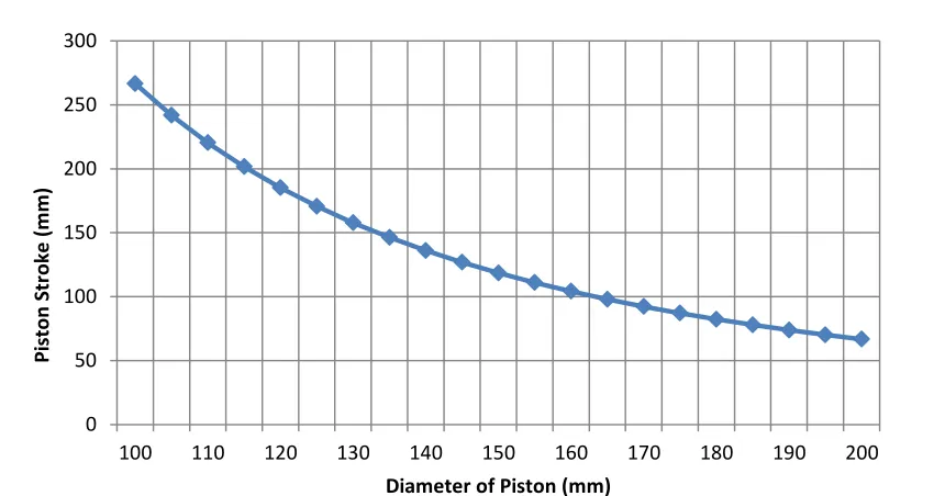
Since the maximum punch stroke of the press is 508 mm, the maximum piston stroke must be somewhat less than this in order to displace a volume of fluid within the compression chamber that will fully bulge a sheet specimen. Table 2 presents the volume change per millimeter of piston displacement as well as the piston stroke required to achieve maximum volume capacity, for selected piston diameters.
Piston Diameter (mm)
Volume Change Per 1 mm Piston displacement
(mm3)
Maximum Piston Stroke to Achieve Desired Volume (mm)
% of Maximum Press Piston
Stroke
100 7853 266 52.49%
105 8659 241 47.61%
110 9503 220 43.38%
115 10386 201 39.69%
120 11309 185 36.45%
125 12271 170 33.60%
130 13273 157 31.06%
135 14313 146 28.80%
140 15393 136 26.78%
145 16513 126 24.97%
150 17671 118 23.33%
155 18869 111 21.85%
160 20106 104 20.51%
165 21382 97 19.28%
170 22698 92 18.16%
175 24052 87 17.14%
180 25446 82 16.20%
185 26880 77 15.34%
190 28352 73 14.54%
195 29864 70 13.80%
200 31415 66 13.12%
Table 2. Piston diameter, volume change per mm of piston displacement and percentage of maximum stroke
35
being used. The entire range of piston diameters is thus acceptable with respect to displacing the required maximum volume of fluid. As mentioned in Chapter 2, a smaller volume change per millimeter of piston displacement is beneficial as it allows better control of the sheet bulging process.
As the maximum piston stroke is increased in the design, so also does the size of the pressure chamber as well as the overall size of the die. In order to minimize the cost of the die, the volume of steel needed to build the die must also be minimized. Therefore, an appropriate combination of piston diameter and piston stroke was determined in order to achieve the complete bulging of sheet specimens and good process control while limiting the cost of the die.
Figure 3-2. Required piston stroke to achieve desired volume
Step 3: determination of piston diameter.
Designing a piston that is capable of sealing pressures illustrated in Figure 3-1 was challenging when considering 100 to 200 mm diameters. After research, the greatest standard piston size that could be purchased was found to seal up to a pressure of 69.9 MPawith a diameter of 120 mm. A pressure greater than this would lead to the seal
0 50 100 150 200 250 300
100 110 120 130 140 150 160 170 180 190 200
Pi
sto
n
Str
o
ke
(
m
m
)
36
failing. Thus a piston diameter of 120 mm was chosen, this provided a good combination of maximum achievable pressure as well as volume change per mm of piston
movement. This also allowed the tooling of the press to be small enough to fit into the opening of the hydraulic press; a higher stroke would have required a bigger tool in terms of height. With a piston diameter of 120 mm, the current working space between the upper and lower dies when the press is fully opened is 6 inches; any smaller of a piston would have resulted in a working space of only 4-5 inches, which is not practical. Two solutions were produced in order to ensure that the pressure does not exceed 69.9 MPa.
Solution 1: The maximum punch force was reduced to 780 kN in order to ensure that with a piston diameter of 120 mm the maximum pressure achievable did not exceed 69.9 MPa.
Solution 2: The pressure transducer was set-up with a cut-off point, as soon as the pressure reached a certain value that was programmed, the press would turn off and thus the pressure would be immediately stopped. A safety factor of 1.1 was also incorporated.
By implementing two safety precautions, one in the maximum press force, and one in the software of the press, the piston pressure will not exceed 69.9 MPa.
37
In the FE simulation, the 8650 wrought steel specimen was bulged to the maximum bulge height, in this case one half of the 135 mm diameter, a bulge height of 67.5 mm, and this required a predicted pressure 52 MPa. This demonstrates that 69 MPa is indeed sufficient to bulge DP600 to the desired bulge height considering that 8650 wrought steel has a higher yield and tensile strength while also being thicker.
A maximum pressure of 69 MPa also provides the capability to carry out bulge tests up to the onset of failure using AHSS sheet specimens with greater tensile strength and/or greater sheet thickness than even this 8650 wrought steel reference material that was used in this numerical simulation.
3.2 Clamping the sheet specimen
When conducting a hydraulic bulge test, it is necessary to stretch-form the specimen so that it is subjected to fully balanced biaxial tension. This requires that the specimen be securely clamped around its periphery in order to avoid any material drawing in.
However, the closing force of the blankholder may not be sufficient when testing higher strength sheet materials. If the blankholder force is insufficient, there is a risk that the sheet material will flow into the forming zone. The maximum blankholder force capacity of the press is also 1000 kN. In cases where this blankholder force is not sufficient to securely clamp the specimen, the bulge test die was designed with an additional clamping mechanism.
The hydraulic bulge test die was designed with a support ring that can be used to bolt the sheet specimen into place using 12 M12 bolts which have a minimum tensile strength of 400 MPa [63]. This bolted support ring allows for an additional distributed load to be applied around the periphery of the specimen and also ensures that the specimen will not draw in during a bulge test.
38
materials, configuration 1 offers the convenience of saving the time and cost involved in drilling holes in each circular blank prior to testing. However, high strength sheet materials usually require the additional clamping force provided by the bolted support ring.
A third clamping solution was also considered for higher strength sheet materials in which the blank would be held in place using a lockbead. The upper die is removable, and thus it would be possible to design an upper and a lower ring with a mating
lockbead. The mating upper and lower rings would be designed with clearances suitable for a narrow range of sheet thicknesses and might also allow for the height of the lockbead to be adjustable, depending on the severity of the bends required to lock the sheet material [64].
The final design of the bulge test die has the following key dimensions shown in Table 3:
Piston Diameter 120 mm
Diameter of the cavity in the upper die 135 mm
Number of M12 bolts 12
Radius of the fillet 3 mm
Maximum Piston Stroke 170 mm
Maximum Force 10,000 kN
Table 3. Bulge test critical parameters
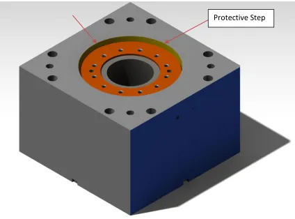
A detailed component list of the bulge test die can be found in Appendix 1 3.3 Main die block
The main die block, shown in Figure 3-3, has a length of 400 mm, a width of 395 mm and an overall height of 265 mm. There are 12 concentric threaded holes around the
39
a test, the oil under pressure will first hit the protective step rather than endangering the press operator.
Figure 3-3. Main die block (Catia model)
3.4 Clamping ring
The clamping ring was designed with the purpose of securely clamping and sealing the specimen around its periphery, while allowing it to bulge up inside the ring. The two black arrows show the position of the clamping ring in Figure 3-4. The clamping ring incorporates two locating holes so that the locating pins will ensure that the clamping ring is always located in a consistent position.
40
Figure 3-4. Clamping ring with 12 bolt holes and 2 locating holes (Catia model)
The inside diameter of the clamping ring is 135 mm, which allows the sheet material to bulge out within this opening. A 3 mm radius, as can be seen in Figure 3-5, on the inside fillet of the clamping ring ensures that the specimen does not shear when the sheet specimen bulges and wraps around this inside radius.
41
Figure 3-5. Clamping ring with 12 bolt holes and 2 locator holes (Catia model)
3.5 Upper die block
The upper die block was designed to close down onto the clamping ring to hold the sheet specimen in place and seal the pressure chamber during a bulge test. This was implemented by designing a 50° chamfer from top to bottom. The eight threaded holes are used to install the upper block onto the top of the Eagle press, and the four slots are used to locate the upper block in place.
This design of the upper die block also includes a central opening that allows the digital cameras mounted on top of the press to focus on the specimen through the large chamfered opening in the crown of the press, while providing sufficient light to properly illuminate the test specimen. This allows the digital cameras to record higher quality images due to a lower aperture being used. Figure 3-6 illustrates the upper die block.
42
Figure 3-6. Upper die block with central chamfered opening (Catia model)
3.6 Piston and honed tube
A custom piston head was designed so as to be able to accommodate a specialized seal that can operate up to a maximum specified pressure of 69.9 MPa. This piston head was machined and customized in order to meet the requirements of the seal manufacturer and ensure that the maximum operating pressure could indeed be attained.
A custom honed tube was purchased that is specifically designed for uses in hydraulic fluid applications. The honing process involves using abrasive polishing stones and abrasive paper to remove small amounts of material and produce an inside surface with very precise dimensions and tolerances, and a surface roughness no greater than 0.4 µm. A Team Tube-Metric Honed tubing was used with an inner diameter of 120 mm, an outer diameter of 6 inches and a length of 245 mm. The honed tube is made of a
43 3.7 Seals, O-rings and fittings
An AS568-225 O-Ring was selected with an inner diameter of 47.22 mm and a cross- section of 3.53 mm, and was mounted on the top surface of the piston head, as
indicated by the black arrow in Figure 3-7. Figure 3-8 shows the technical drawing of the seal.
Figure 3-7. AS568-225 O-Ring
44
A specialized Selemaster DSM piston seal was purchased that was selected based on the 120 mm piston diameter size. Selemaster piston seals are manufactured with a highly compression resistant nitrile. This allows it to reach very high pressures. Figure 3-9 shows the schematic for the Selemaster DSM piston seal.
Figure 3-9. Selemaster DSM piston seal schematic
Dn 120 mm
d 100 mm
L 35 + 0.2 mm
L1 9.52 + 0.1 mm
d1 112.80 +/- 0.05 mm
d2 117.5 +/- 0.07 mm
Table 4. Selemaster DSM piston seal parameters
Fittings are used as leak-free connections for power and instrumentation in the bulge test design. In order to properly connect the pressure transducer and the dump valve proper fittings were needed. A Parker high-pressure 69.9 MPa pipe fitting steel ½ ‘’ inch NPT (National Pipe Taper) nipple, Figure 3-10, as well as a Parker high-pressure 10k pipe fitting steel ½ ‘’ NPT 90 degree elbow, Figure 3-11, were used for the pressure
45
Figure 3-10. Pipe fitting 1/2'' NPT nipple
T1 ½ ‘’
T2 ½ ‘’
W Hex 7/8’’
D ins. 1.89 ‘’ Table 5. NPT nipple parameters
Figure 3-11. Pipe fitting 1/2'' NPT elbow
Thread Size ½’’
A 1.31”
B 1.32”
C A/F 1.00”
46 3.8 Pressure transducer
In order to continuously measure and record the actual pressure inside the pressure chamber of the bulge test die, it was designed to be equipped with a built-in pressure transducer. A Barksdale 423 series general industrial (amplified) pressure transducer was selected because of its compatibility with the control system and data acquisition system of the hydraulic press. An excitation voltage of 24 VDC was used with an output of 4-20 mA and a secondary output possible with 0-10 volts. A range of 0-69 MPa is available with a frequency response of 2 kHz and a resolution of 0.006895 MPa. Figure 3-12 shows a photograph of the pressure transducer that was used. The electrical connection was made with a 3 conductor, 24 American wire gauge (AWG), PVC jacked, shielded cable that is 1.0 m long with integral strain relief and case grounding.
47
Chapter 4 Experimental Procedures
4.1 Tensile test procedures
Rectangular blanks were flat rolled to effective strains of 0.2, 0.4, 0.6, 0.8 and 1.0 and then were prepared for tensile tests following ASTM E8 standards. Electro-etching was used to measure the width strains of the specimen and DIC measurements were used in conjunction with a mechanical and video extensometer to calculate the principal strains. A Matlab code was created to produce the flow stress curve.
4.1.1 Specimen preparation
A guillotine shear was used to cut tensile specimens to a width of 30 mm and an overall length of 500 mm. Figure 4-1shows the dimensions required by the ASTM E8 [65] standard for thin sheet metals. The overall length is to be 200 mm, while the overall height should be 20 mm. By shearing the sheet to a length of 500 mm, two tensile specimens can be machined to the final shape using wire-EDM. An overall height of 30 mm allows for a sufficient working tolerance to properly machine the tensile specimens.
48
Parameters Dimension (mm)
L 180
B 41.671
A 60
W 12.5
C 20
G 60
R 30
t 1.5
Table 7. Tensile test specimen parameters and dimensions
4.1.2 Electro-etching
Digital image correlation (DIC) can be used to measure the strain distribution across the gauge area of a tensile test specimen. A random speckle pattern can be applied onto the tensile test specimen and both an initial and a final picture of the specimen can be taken, once the successive rolling is completed. This allows for the DIC to record an original, un-deformed configuration to which all images of deformed configurations can be compared. A virtual width strain can be implemented on the two images and thus a virtual gauge can be applied. The virtual strain gauge would then be used to calculate the width strain that resulted from the rolling.
Etching a grid onto the surface of the specimens is a more common and practical way of determining strains and this method that was used to calculate width strains. Strips of DP600 steel were electro-etched prior to pre-straining by flat rolling. A thorough
cleaning of the specimen was first carried out and clean gloves were used to handle the specimen since fingers contain natural oils that would negatively affect the etching process and result in a poorer quality etching finish.
49
lead to less accurate results in the subsequent tensile tests. If the etching is not sufficiently deep, the grid may be removed during the rolling process.
There are several different stencil patterns that can be used for etching a sheet metal blank, and the most common are squares and circles. Squares are easier for calculating the deformation and thus the width strain in this case. An electro-etched specimen is shown in Figure 4-2.
Figure 4-2. Photograph of the electro-etched grid on a tensile specimen
4.1.3 Rolling tests
50 Specimen
Designation
Average Thickness
Rolling Direction
(mm)
Average Thickness
Transverse
Direction (mm)
SR1-1 1.483 1.484
SR1-2 1.493 1.481
SR2-1 1.494 1.483
SR2-2 1.492 1.484
SR3-1 1.494 1.484
SR3-2 1.490 1.487
SR4-1 1.491 1.486
SR4-2 1.491 1.486
SR5-1 1.491 1.484
SR5-2 1.484 1.482
SR6-1 1.486 1.488
SR6-2 1.491 1.485
Table 8. Specimen name and thickness in rolling and transverse direction
In order to calculate effective strains with proper increments between one another, a theoretical analysis of the rolling was done. By manipulating the following equations:
̅ √ ( ) (26)
(27)
and assuming constancy of volume
(28)
51
(29)
Rolling was carried out in successive stages, and the desired effective strain increments at each stage were chosen to be 0.0, 0.2, 0.4, 0.6, 0.8, and 1.0 each being associated with specimen SR1, SR2, SR3, SR4, SR5 and SR6, respectively. This allowed for an even distribution of effective strain in successive specimens. With these values being substituted into Eqn. (27), the only unknown left is . Table 9 shows the calculated theoretical and the experimental values obtained for the rolling direction.
Specimen Designation Theoretical Thickness Rolling Direction (mm) Total Theoretical Effective Strain - Rolling Direction Measured Thickness Rolling Direction (mm) Total Experimental Effective Strain - Rolling Direction
SR1-1 1.483 0.0 1.483 0.0
SR1-2 1.493 0.0 1.493 0.0
SR2-1 1.256 0.2 1.262 0.193
SR2-2 1.255 0.2 1.259 0.196
SR3-1 1.057 0.4 1.067 0.386
SR3-2 1.054 0.4 1.067 0.386
SR4-1 0.887 0.6 0.892 0.593
SR4-2 0.887 0.6 0.894 0.591
SR5-1 0.746 0.8 0.764 0.772
SR5-2 0.742 0.8 0.736 0.815
SR6-1 0.625 1.0 0.631 0.993
SR6-2 0.627 1.0 0.625 1.004
Table 9. Rolling theoretical thickness and effective strain in comparison to achieved thickness and effective strain
![Figure 1-2. Variation in FEA extrapolation [8]](https://thumb-us.123doks.com/thumbv2/123dok_us/1391599.1171874/18.612.201.449.126.333/figure-variation-in-fea-extrapolation.webp)
![Figure 2-1. Stress as a function of percent prior cold work and strain [12]](https://thumb-us.123doks.com/thumbv2/123dok_us/1391599.1171874/23.612.239.449.73.279/figure-stress-function-percent-prior-cold-work-strain.webp)
![Figure 2-4. Gerhard Gutscher’s design of a bulge test [18]](https://thumb-us.123doks.com/thumbv2/123dok_us/1391599.1171874/26.612.131.529.277.522/figure-gerhard-gutscher-s-design-of-bulge-test.webp)
![Figure 2-6. Static loading (left) vs. impulsive loading (right)[20]](https://thumb-us.123doks.com/thumbv2/123dok_us/1391599.1171874/27.612.133.517.263.553/figure-static-loading-left-vs-impulsive-loading-right.webp)