Experimental Study of Flow Characteristic at
Horizontal Mini Channel
Othman Ashafai Othman Atpoly1, Budi Santoso2, Dwi Aries2, Ammar Mufrih2, Latif Ngudi Wibawanto2
1P. G. Student, Post Graduate Program of Mechanical Engineering, Sebelas Maret University, Indonesia
2
Department of Mechanical Engineering, Sebelas Maret University, Indonesia
ABSTRACT: The small or mini channel is widely adopted in compact heat exchanger in particular. In present study, the values of velocity and gas void fraction in two-phase gas-liquid flow in mini-channels were experimentally determined. The depth and width of the rectangular cross-section of the channel were 3 mm x 3 mm and 3 mm x 6 mm. The investigated flow and channel size to be applied in measurements of velocity and gas void fraction, a method based on the digital image analysis was applied. The value of gas phase velocity was defined by the values of distribution parameter C0. The relation describing the value of gas void fraction depended on the Bankoff coefficient and gas input
volume fraction.
KEYWORDS: Two phase flow, Flow pattern, Bubble velocity, Horizontal mini channel, Void fraction.
I. INTRODUCTION
The flow of two phases (air and water) is related to many device and application such as power generator unit, nuclear industry, micro electric device, etc, which occurred heat transfer on all of it. This condition makes a great demand in optimizing the efficiency of heat exchanger design by heat removal techniques to dissipate increasingly large heat flux. The use of air and water as the working fluids at two-phase flow with mini rectangular channels will conduct in this research to know the effect of channel size. The main parameters are void fraction or superfractial velocity or bubble velocity at horizontal mini channel.
The investigation of flow phenomena in a mini channel is very important since this kind of application is used as heat exchanger. The differences between the vertical and the horizontal channel cause noticeable differences in the measured parameters in the annular flow region where JG is larger than about 10 ms−1 [1]. Huang et al. [2] described a
method for the identification of gas-liquid two-phase flow regime in mini-pipes based on textural feature series. A high-speed image acquisition system is used to capture images of gas-liquid two-phase regimes in the mini-pipe and five typical flow regimes (stratified flow, wavy flow, bubbly flow, slug flow and annular flow) are observed.
Based on description that has been mentioned above, the researcher is interest in studying about the two-phase flow air and water at rectangular mini channel due to the characteristics.
II. THEORY
An air-water mixture flow in a pipe can exhibit a variety of shapes and distributions of interfacial surfaces which can be used to determine the characteristics of the flow. The flow patterns have direct effect on the pressure drop and the heat transfer characteristics of the fluid. A view of flow patterns is shown Fig. 1. Data collected from observations of flow patterns can be expressed in a flow pattern map. This flow pattern maps are used to determine the flow patterns that occur based on the given conditions. Mandhane et al. [3] makes the flow pattern map with the coordinates of the superficial liquid velocity (JL) and superficial gas velocity (JG) divided into patterns of bubble flow, plug, stratified,
Fig. 1. Huang’s flow patterns [1] modified
The measurement of bubble size, bubble velocity, and specific interfacial area in two-phase flow of air and water has always been a challenging problem. Bubble velocity measurement is used to determine the value of C0 and uG in the
bubble nose velocity equation that proposed Ide and Fukano [4].
𝑢𝐺= 𝐶0 𝐽 + 0.35 𝑔𝐷𝐻 for 𝐽 ≤ 0.3 𝑚/𝑠
𝑢𝐺= 𝐶0 𝐽 for 𝐽 > 0.3 𝑚/𝑠
Where C0 is the distribution parameter and equals 1.2.
The value of mean gas void fraction was derived from the relation:
𝛼 = 𝐽𝐺
𝑢𝐺
On the other hand, the value of gas input volume fraction was determined from the following equation:
𝜀 =𝐽𝐺
𝐽
In majority of two-phase flows, the values of mean gas void fraction are smaller than the values of gas input volume fraction. Obviously, this phenomenon stems from the greater gas phase flow velocity than the liquid phase flow velocity. From the research carried out by Ali et al. [5], it may be concluded that, similarly, during two-phase flow in micro- and mini-channels gas input volume fraction 𝜀 depends on mean gas void fraction 𝛼 in a mini-channel:
𝛼 = 𝐾𝜀
Ali et al. [5] also found that the value of the Bankoff coefficient K was equal to 0.8 during two-phase water-gas flow. In the study an attempt was made to determine the values of the Bankoff coefficient during the two-phase mixture flow in mini-channels.
III. METHODOLOGY
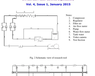
Fig. 2Schematic view of research tool
Fig. 3 The top view of test section
Fig. 2 and Fig 3 show a schematic diagram of the experimental apparatus used in the present study. Air supplied from a compressor and water from pump into an air-water mixing section after their flow rates are measured individually by flow meters. The image of the two-phase mixture flowing in the channel was recorded using a high-speed Casio EX-ZR1000 camera. The speeds of videos are 1000 frames/sec. The measuring system consisted of a video camera mounted in top of the test section in which two-phase flow took place and a lightening system put at bottom test section. The images were analysed using software PHANTOM 630 to generate parameter data flow patterns and the bubble velocity.
IV. RESULTS AND DISCUSSION
Fig. 4 until Fig. 6 shows the typical results of the flow patterns obtained from the present experiment. The figures 4, 5 and 6 correspond to interfacial behaviour of the bubble, plug and annular flows, respectively. The increasing in
superficial velocity of both test section shows the changing of bubble sizes and the shape of bubble itself.
Jl= 0.185 m/s; Jg= 0.185 m/s Jl= 0.093 m/s; Jg= 0.093 m/s
Jl= 0.370 m/s; Jg= 0.185 m/s Jl= 0.185 m/s ; Jg= 0.093 m/s
Jl= 0.556 m/s; Jg= 0.185 m/s
(a)
Jl= 0.278 m/s ; Jg= 0.093 m/s
(b) Notes:
1. Compressor 2. Regulator 3. Filter air 4. Air flow meter 5. Pump
Jl= 0.185 m/s; Jg= 0.556 m/s Jl= 0.093 m/s; Jg= 0.278 m/s
Jl= 0.185 m/s; Jg= 0.741 m/s Jl= 0.093 m/s; Jg= 0.370 m/s
Jl= 0.185 m/s; Jg= 0.926 m/s Jl= 0.093m/s; Jg= 0.463 m/s
(a) (b)
Fig. 5 The plug flow patterns for (a) the 3 mm x 3 mm channel and (b) the 3 mm x 6 mm channel
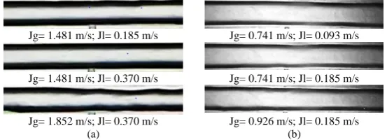
Jg= 1.481 m/s; Jl= 0.185 m/s Jg= 0.741 m/s; Jl= 0.093 m/s
Jg= 1.481 m/s; Jl= 0.370 m/s Jg= 0.741 m/s; Jl= 0.185 m/s
Jg= 1.852 m/s; Jl= 0.370 m/s Jg= 0.926 m/s; Jl= 0.185 m/s
(a) (b)
Fig. 6 The annular flow patterns for (a) the 3 mm x 3 mm channel and (b) the 3 mm x 6 mm channel
(a) The 3mm x 3 mm channel (b) The 3mm x 6 mm channel
Fig. 7 Flow pattern observation at Mandhane’s Flow Pattern Map [3]
The obtained flow pattern data is compared with the horizontal flow pattern map proposed by Mandhane et al. [3] as shown in Figure 7. Close observation of this figure reveal that the obtained flow pattern data are not in agreement with those of Mandhane et al. [3]. Finally, the present study proposed the new flow pattern map as shown in Fig. 8.
Fig. 9 shows a comparison of the values of gas velocity in the 3 mm x 3 mm channel and 3 mm x 6 mm channel. In the present experiment, the values of C0 are 1.68 and 178, respectively. The value of C0 for 3 mm x 3 mm channel is
(a) The 3 mm x 3 mm channel (b) The 3 mm x 6 mm channel Fig. 8 Flow pattern map for present observation
(a) The 3 mm x 3 mm channel (b) The 3 mm x 6 mm channel Fig. 9 The bubble velocities
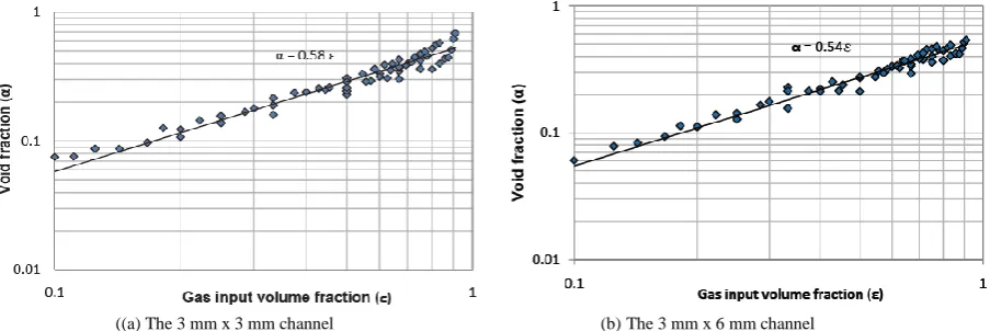
((a) The 3 mm x 3 mm channel (b) The 3 mm x 6 mm channel Fig. 10 Void fractions at different gas input volume fraction
From the test results, analysis of data and discussion of research can be concluded as follow:
1. The identification of the flow patterns were based on visual observations of flow pattern using video technique as the methodology used in this study. The observed flow patterns were classified in three major flow patterns: bubble, plug and annular flow regimes.
2. The new flow pattern map was proposed for 3 mm x 3 mm channel and 3 mm x 6 mm channel.
3. The model was applied to define the velocity and void fraction during two-phase gas-liquid flow in mini-channels. A relation was proposed to describe the distribution parameter. A relation enabling determination of the values of mean gas void fraction in two-phase mixture flowing in a mini-channel was obtained. The value of mean gas void fraction was made dependent on the values gas inlet volume fraction.
.
REFERENCES
[1] Hideo Ide, Akira Kariyasaki, and Tohru Fukano, “Fundamental Data on The Gas-Liquid Two Phase Flow in Minichannels”, International Journal of Thermal Sciences, Vol. 46, p. 519-530, 2007.
[2] Gang Huang, Haifeng Ji, Z. Huang, B. Wang, and Haiqing Li, “Flow Regime Identification of Mini-Pipe Gas-Liquid Two-Phase Flow Based on Textural Feature Series”, Journal of Department of Control Science and Engineering, Zhejiang University, 2011.
[3] J. M. Mandhane, G.A Gregory, and K. Aziz, “A Flow Pattern Map For Gas-Liquid Flow in Horizontal Pipes”, Trans ASME, Vol. 64, p. 193-200, 1974.
[4] H. Ide, and T. Fukano, “Experimental research on the correlations of holdup and frictional pressure drop in air-water two-phase flow in capillary rectangular channel”, Experimental Thermal Science, 29, 833–841, 2005.
[5] M. Ali, M. Sadatomi, M. Kawaji, Adiabatic two-phase flow in narrow channel between two flat plates, Can. J. Chem. Eng., 71, 657–666, 1993.