Transactions of the 17th International Conference on Structural Mechanics in Reactor Technology (SMiRT 17) Prague, Czech Republic, August 17 –22, 2003
Paper # G04-3
Storage Containers Optimized for Recycling
D. Bounin 1), W. Kleinkröger 1), D. Schreiber2)
1) Siempelkamp Giesserei, Krefeld, Germany
2) GNS, Gesellschaft für Nuklear-Service, Essen, Germany
ABSTRACT
In the decommissioning of nuclear plants large quantities of radioactively contaminated scrap metal have to be disposed of. An economic alternative to final storage is their recycling in the production of transport and storage containers for low and medium active waste made of nodular graphite cast iron. As part of the design requirements for storage containers it must be shown that there will be no crack initiation from drops without impact limiters onto solid rock targets at low temperatures. In order to guaranty a sufficient safety level for the fracture toughness the share of the cast iron microstructure that leads to brittle behaviour (pearlite and carbides) is limited to 20% in the presently licensed containers. This requires severely limiting the type and quantity of recycled metals. These usually are steels with sizeable contents of elements like either manganese or chromium, nickel, molybdenum and copper and whose presence in the melts lowers fracture toughness. Presently, part of the scrap cannot be recycled into containers.
Based on this background the research program FORM investigates ways to raise the amount of recycled metals in the production of containers while at the same time meeting the design requirements for transport and storage containers without crack initiation. In order to achieve this goal the relations between chemical composition of the casting and manufacturing process on one side and the resulting cast iron microstructure and material properties on the other side must be investigated.
As an important step the optimization of the structural design of the container shall reduce material stresses resulting from a given external loading. With respect to the dynamic precalculations of the drop tests required for final storage the behaviour of the target as well as the interaction of target and container must be better understood than is presently the case. Casting exactly to specification, in order to obtain the specified microstructure and material properties, verification of material properties by quality control and successful drop testing of containers with machined artificial flaws are central parts of the R&D program FORM.
Parallel to the material investigations the structural design of 2 container types was optimized such as to reduce the maximum stresses under impact loading by nearly half. Both prototypes were manufactured with inactive materials and machined with artificial flaws in critical locations and orientations. The flaws were sized thus as to result in a precomputed safety factor of 1 against crack initiation under drop test impact.
The prototypes have successfully passed drop tests at -20°C. This is an important step towards proving the feasibility of transport and storage containers with increased amounts of recycled metals. The low dynamic fracture toughness did not result in failure. This is due the high strength and the reduced stress levels of the optimized containers. The fracture toughness of high-pearlite material is not much influenced by low temperatures and dynamic loading rates. Present investigations are towards further raising the recycling levels.
In a series of drop tests the behaviour up to actual failure under impact will be investigated. Dummies made of a selected inactive reference recycling material will be used. These dummies will receive machined flaws and will be drop tested from heights according to and exceeding standards.
BACKGROUND
In the decommissioning of nuclear plants large quantities of radioactively contaminated waste metal have to be disposed of. An economic alternative to final storage is the recycling of the scrap metal in the production of transport and storage containers for low and medium active waste made of nodular graphite ductile cast iron. In the particular case of the CARLA plant operated by Siempelkamp, scrap metal with an activity of up to 200 Bq/g is accepted for processing. This covers the vast majority of the metals of a plant to be decommissioned.
After solidification of the high-carbon, high-silicon cast iron melt the carbon has formed nodular graphite particles embedded in the metal matrix. Nodular cast iron has high strength and elongation. A further advantage of this material are its good radiation shielding properties.
Fracture toughness is an important material property in the design of containers for final storage. In the particular case of containers that have to meet the specifications for final storage these must withstand accident loadings from a height of up 5 m at temperatures of as low as -40°C without crack initiation. Containers for final storage do not have the benefit of impact limiters. The fracture toughness of cast iron depends primarily on the microstructure of the metal matrix. A ferritic microstructure has a higher fracture toughness than a pearlitic microstructure. Carbides in the matrix
lead to embrittlement. The metals to be recycled in the decommissioning of a nuclear installation have marked contents of elements like manganese (Mn) in structural steels, chromium (Cr), nickel (Ni) and molybdenum (Mo) in stainless steels and copper (Cu) in special steels. These elements lead to a pearlitic microstructure and to carbides, already even at low contents in the melts. With a rising content of pearlite and carbides, the tensile and yield strength increase while elongation to rupture and fracture toughness decrease. In order to meet the requirements on sufficient ductility and fracture toughness the specifications for the presently licensed containers limits the embrittling content of pearlite in the microstructure to 20% of the cross section of a metallographic specimen. In order to meet this limit on pearlite type and quantity of waste metal that can presently be recycled is very limited.
GOALS AND METHODS
Based on this background the research program FORM [1] and [3] investigates ways to raise the amount of recycled metals in the production of containers while at the same time meeting the design requirements for transport and final-storage containers. In order to achieve this goal the relations between chemical composition of the casting and manufacturing process (e.g. casting setup and solidification conditions, which influence the material properties of the product) on the one side and the resulting cast iron microstructure and material properties on the other side must be investigated. By way of optimizing the structural design of the container, the material stresses resulting from a given external loading shall be substantially reduced. With respect to the dynamic precalculations of the full-size container drop tests, required for the licensing for use in final storage, the behavior of the target (solid rock simulated by concrete) as well as the interaction of target and container must be better understood than is presently the case. Mastering of the casting process and of casting exactly to specification, in order to obtain the specified microstructure and material properties in the production casting, and the verification of material properties by quality control are central parts of the R&D program FORM. Drop tests of full-size and dummy containers with machined artificial flaws, after extensive precalculations, are central parts of a complementing R&D program administered by BAM (Bundesanstalt für Materialforschung und -prüfung).
MATERIAL INVESTIGATIONS
In the first phase of the research, testblocks were manufactured that were cast with a wide range of simulated (inactive) waste metal compositions. Taking specimens revealed insights on the influence of the chemical composition on the microstructure and the feasible upper limits for the relevant elements Mn, Cr, Ni, Mo and Cu. One important result was finding out that the decomposition of the high pearlite content in the microstructure in the as-cast condition by heat treatment, was not economically feasible for the desired elevated quantities of waste metal recycling. This ferritising treatment can be successfully employed only for the low amounts of waste metal used in the present manufacturing technology of containers [1] and [2].
In the 2nd phase of the research 2 dummy containers with sigmificant dimensions and casting setup (in the following referred to as ring 1 and ring 2, the cylindrical part of the MOSAIKII container) were cast with the 2 chemical compositions selected from the wide bandwidth of phase one. As intended and expected this lead to castings with 2 differently high contents of pearlite and carbides in the microstructure. Specimens taken from these two rings provided the static and dynamic material properties that could be used one-to-one in the design optimization of the full-size prototype box-shaped container type VII and the prototype MOSAIKII container and the precalculations of their drop tests [3] and [4].
portion of metallic matrix (i.e. without graphite) of a metallographic specimen. The higher contents of Mn and Ni in the ring 2 material result in an almost fully pearlitic microstructure. In addition, the higher contents of Cr results in carbides. The numbers shown in Table 1 on shape and size of the graphite stand for the good quality of the nodular graphite, on the same level as for castings without waste metal.
Table. 1: Content of waste metal (weight-%) and microstructure in the special nodular cast iron
Mn % Cr % Ni % Mo % Cu % Ferrite % Pearlite % Carbides % Graphite shape ISO 945 Graphite size Ring 1 0,3 0,35 < 0,06 < 0,01 0,2 25 75 < 1 VI + (V) 6 – (5)
Ring 2 0,5 0,6 0,5 < 0,01 0,2 5 90 5 VI + (V) 6
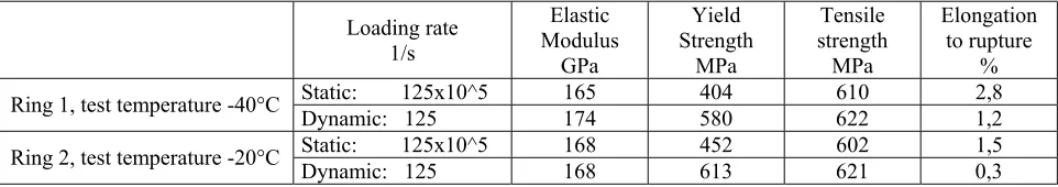
The results of the static tensile tests show the high tensile and yield strengths and the low elongation to rupture, which was expected. Because of the carbides there is a further drop in elongation for the ring 2 material. Under dynamic loading the yield strength rises markedly while tensile strength remains nearly the same. The elongation to rupture takes a further drop. The high yield strengths have the very advantageous effect that stresses in the container material remain in the linear elastic range even under accident loading. Table 2 shows the high strengths of the 2 special cast iron materials selected for reference within the FORM program, the increases in yield strength and the decreases in elongations under dynamic loading. This is graphically illustrated in Fig. 1.
Table 2: Mechanical properties of the special nodular cast iron at room temperature as function of loading rate
Loading rate 1/s Elastic GPa Yield Strength MPa Tensile strength MPa Elongation to rupture %
Static: 125x10^5 165 404 610 2,8
Ring 1, test temperature -40°C Dynamic: 125 174 580 622 1,2
Static: 125x10^5 168 452 602 1,5
Ring 2, test temperature -20°C Dynamic: 125 168 613 621 0,3
Modulus
With the high contents of pearlite the reference container materials of ring 1 and ring 2 display a typically lower shelf fracture toughness. In ring 2, with carbides due to the higher content of Cr, the fracture toughness is not much lower than in the ring 1 material with less Cr. The influence of the loading rate also is quite limited (Fig. 2). Fracture toughness is measured on 3-point bending specimens.
0 100 200 300 400 500 600 700
0 0,5 1 1,5 2 2,5
true strain, %
ring 2, dynamic (-20°C) ring 1, dynamic (-40°C) ring 2, static (-20°C) ring 1, static (-40°C) 0,2% strain
Fig. 1: True stress-strain-diagrams, static and dynamic
Fig. 2: Fracture toughness (incl. trend lines) static and dynamic
3 0 10 20 30 40
1E-1 1E+0 1E+1 1E+2 1E+3 1E+4 1E+5 1E+6 loading rate dK/dt, MPa*m^0,5/s
KIq , M Pa *m ^0 ,5
ring 1 (-40°C)
Testing of the material was continued by casting and taking specimens of upright plates 800 mm wide x 1000 mm high x 160 mm thick. One half of the plate was cast against chills on one surface. With respect to cooling and solidification conditions these test plates represent full size walls for all types of containers for low and medium active waste covered by this research. The amount of waste metals (again as an inactive simulated recycling material) were varied in such a manner as to permit evaluation of the test results in a regression analysis later on. Besides metallographic aspects like pearlite and carbide contents in the microstructure, the upper limits of waste metal content are also given by manufacturing considerations like avoiding shrinkage defects and limiting hardness in order to retain economic machinability. In the future the amount of waste metal in the melt can be planned with the help of the regression analyses to meet the particular requirements.
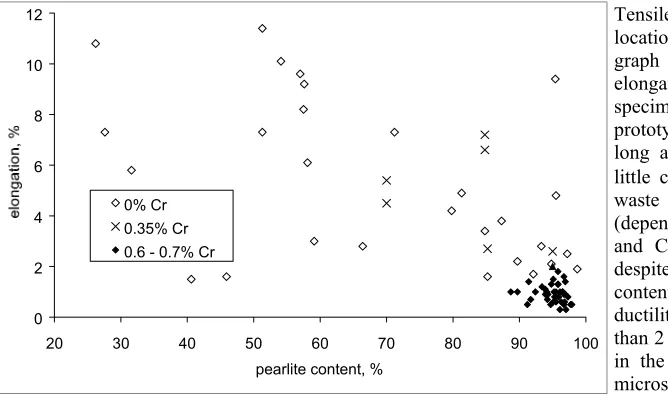
Tensile specimens are taken from five locations on each of the test plates. The graph (Fig. 3) shows the results for the elongation to rupture of 85 plate specimens and of the core samples of the prototype containers described below. As long as the melt contains none or only little chromium (≤ 0.35 weight-%) from waste metal, ductility varies widely (depending on the contents of Mn, Ni, Mo and Cu) and can be as high as 11%, despite of the pearlite. With a chromium content of 0.6 % to 0.7 % the range of ductility becomes small and drops to less than 2 %, which is caused by the carbides in the otherwise almost purely pearlitic microstructure.
Fig. 3: Elongation to rupture as a function of pearlite content in the microstructure for 0 %, 0.35 % and 0.6 % - 0.7 % of chromium
0 2 4 6 8 10 12
20 30 40 50 60 70 80 90 100
pearlite content, % 0% Cr
0.35% Cr 0.6 - 0.7% Cr
DESIGN OPTIMIZATION
Parallel to the material investigations the structural design of containers was successfully optimized with the help of dynamic finite element calculations. Thanks to increases in the transition radii between adjoining walls and between walls and container bottom and by use of extensions (Figs. 10 - 12) that act like built-in shock absorbers, the maximum stresses under impact loading could be reduced by almost half.
In the case of the MOSAIKII, one of the two container types used in the optimization, the highest stresses result from a side drop. For a 0.8 m drop, which corresponds to the requirements on the waste container class II for final storage, the tangential stress that governs the design was brought down by a number of iterations from an initial level of 306 MPa (corresponding to 100%) to a mere 159 MPa (52%) after optimization (Figs. 4 and 5).
y-stresses, N/mm²
inside of cylinder near lid
0,0 0,1 0,2 0,3 0,4 0,5 0,6 0,7 0,8 0,9 1,0
0,0 1,0 2,0 3,0 4,0 5,0 6,0 time,
relative s
tr
ess leve
l
s = l s = 80 mm s = 0 mm
Fig. 4: Tangential stresses in MOSAIKII container
from 0.8m side drop before optimization Fig. 5: Tensile stresses in MOSAIK
II container from 0.8m side drop before and after optimization
0 200 400 600 800 1000 1200
0 2 4 6 8 10 12
time, ms dec el erat ion, g
flat bottom impact
impact on long edge
0 200 400 600 800 1000 1200
0,0 0,5 1,0 1,5 2,0 2,5 3,0 3,5 4
time, ms dece lerat io n, g no recesses
protruding walls (10 mm ) protruding corner fittings (10 mm)
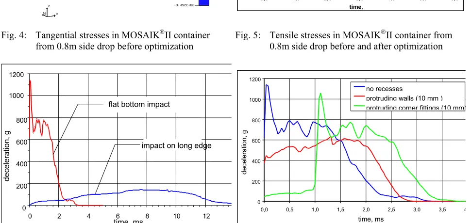
Fig. 6: Computed deceleration of box-type container
after 5 m drop, before optimization Fig. 7: Computed deceleration of box-type container after 5 m drop, before and after optimization
PROTOTYPE CONTAINERS AND DROP TESTS
Both prototype containers were manufactured with chemical compositions (and thus amounts of inactive simulated waste metal) corresponding to the preceding dummy container castings, ring 1 and ring 2. Specimens for tensile testing and determining microstructure were taken from cored samples, the standard quality assurance procedure. Microstructure and graphite nodules were found to be in good accordance with those for the two rings. The moderate level of 0.3% of chromium in the melt led to 2% of carbides in the microstructure of the box-type container Tables 1 and 3). The values for static strength and elongation in the container, measured at room temperature, are somewhat lower than in ring 1, measured at -40°C, which is to be expected. For the MOSAIKII container the corresponding values are nearly identical with those of ring 2, which is a very good result, again in consideration of the different temperatures RT and -20°C (Tables 2 and 4).
Table 3: Content of waste metals in melt and microstructure in the two prototype containers
Mn % Cr %
Ni % Mo %
Cu
Table 4: Tensile tests on cored samples from prototype containers under static loading at ambient temperature
Yield strength
MPa Tensile strength MPa Elongation %
Box-type container 354 579 4,8
MOSAIKII container 443 591 1,8
Fracture toughness cannot be determined from the small cored samples. However, after the drop tests sufficiently large samples can be taken from both containers. The results are already available for the MOSAIKII container (Table 5, those for the box-type containers will have to wait until after a further drop test scheduled later in the program). The fracture toughness has been determined at dynamic loading rates on 3-point bending specimens from samples taken from the wall (this corresponds to ring 2) and from the bottom of the MOSAIKII container. The regions selected are those that experience the highest stresses in side drop and bottom drop accidents. In both regions the fracture toughness was found to be higher than in ring 2. This is a very good result.
Table 5: Fracture toughness measured on specimens from dummy and from full size prototype container
Fracture toughness KIq, MPa*m^0,5 at -20°C under dynamic loading rate
Ring 2 (dummy container) 20
Wall of MOSAIKII container 26
Bottom of MOSAIKII container 23
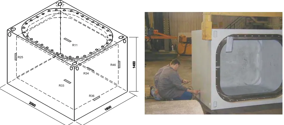
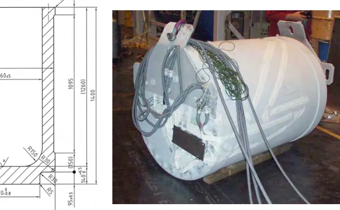
The recesses in the outside surfaces of the prototype containers, respectively the radial and axial extensions that act like built-in shock absorbers, can be seen in Figs. 10 to 12. Figs. 9 and 10 also show the increased transition radii on the insides of the prototype containers. Both containers received machined artificial flaws at all locations of calculated maximum stresses from drop test loading. Fig. 8 shows the locations of the 6 flaws in the box-type container. Flaw size and orientation were selected such as to make precalculated applied stress intensity factors Kappl equal to the material properties Kmat measured on rings 1 and 2. The calculated safety factor was such set equal to one. The artificial flaws of the box-type container had a depth of ca. 7 mm and a length of ca. 90 mm. The two artificial flaws of the MOSAIKII container were located at the 6 o’clock and 12 o’clock positions of the cylinder, each with a depth of 5 mm and length of 24 mm. All artificial flaws could exactly be located and their depth safely sized by ultrasonic testing (Fig. 9). Depth and width were widely overestimated in the UT.
R11
R46 R25
R33
R36 R34
Fig. 8: Major dimensions of box-type container
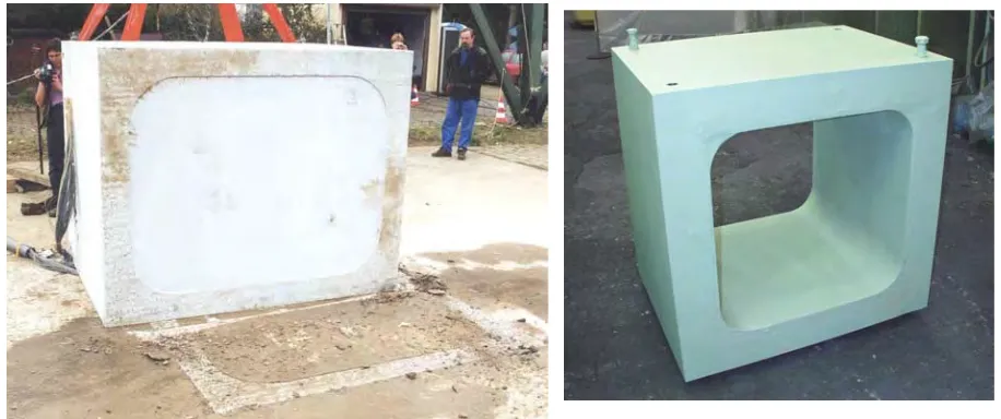
Both prototype containers have successfully passed their drop tests at -20°C onto concrete targets simulating final storage bedrock conditions (Figs. 11 and 12). The shock-absorbing design optimization did its precalculated work. The successful drop tests of the prototypes are an important step towards proof of feasibility of containers with elevated content of waste metal. The low dynamic fracture toughnesses of the pearlitic and carbidic nodular cast iron did not lead to crack initiation as was shown by microscopy of the artificial cracks of the MOSAIKII container. The basis for this success lies in the high material strength, further increased by dynamic loading and low temperatures, and the very much reduced stress levels after design optimization. Also, the post-test investigations of the MOSAIKII container have shown that fracture toughness was somewhat higher than anticipated (Table 5). The low fracture toughness nevertheless requires an exact fracture mechanics analysis.
Fig. 10: Design of prototype MOSAIKII container Fig. 11: Prototype MOSAIKII ready for drop test at -20°C
Evaluation of the drop test of the box-type container showed deceleration and stresses to have been lower than precalculated. The reasons for this were traced to a test target that was less stiff at its surface than intended and to an incomplete understanding of the interaction of container and target at impact. This shows the need to improve the finite element simulation of the drop test onto the bedrock target of final storage (that is not infinitely stiff like the IAEA target). In any case, the box-type container will be machined again for a second set of larger cracks and be subject to a second 5 m drop test.
CONTINUATION OF RESEARCH AND OUTLOOK
There are a number of goals for the third phase (FORM III) of the R&D program. For one, work is under way to establish the statistically verified relationships between the major manufacturing and material parameters like chemical composition of the melt, content of metal waste, casting setup, microstructure and mechanical properties in the container. A series of test plates with dimensions and setup relevant for container manufacturing has been cast, inspected by the standard nondestructive ultrasonic and penetrant testing and than cut into specimens for destructive testing. The statistically verified relationships just mentioned in the future will permit to select melt composition and casting setup such as to meet the required material properties as well as to economically optimize the amount of recycled waste metals. An (inactive) reference material for the manufacturing of further dummy and full containers has already been the selected.
dimensions, casting setups, material properties and drop test behavior that are relevant for the complete containers (Fig. 13). The first series of drop tests has served to establish and verify the behavior of the dummy containers and the interaction with the target as well as to benchmark the computer calculations. For the following two series of drop tests large artificial flaws will be machined in those locations with the highest stresses due to impact. After the drop tests (with stepwise increased drop heights exceeding standard requirements) the dummies will be cut up and investigated for any crack initiation.
Based on the results of the drop tests with the dummy containers and further numerical optimization a second MOSAIKII container will be manufactured and drop tested from the increased height of 5 m that is required for a class II container. The existing box-type container will be machined with a second set of flaws that will be much larger set than the existing first set. Then there will be a second 5 m drop test for this container followed by post-test investigation of the flaw for crack initiation and verification of the in-situ material properties.
Fig. 12: Box-type container after 5 m drop test onto simulated target for final storage
Fig. 13: One of the dummy containers for the series of drop tests
CONCLUSIONS
Recycling metal wastes causes the cast iron container material to have a pearlitic microstructure with low ductility. The optimization of the container design has reduced stresses resulting from accident loading by almost a factor of 2. Full size containers have passed the drop tests required for final storage. Compared to the present level of recycling the amount of metal waste in the containers can be increased by a factor of 3 to 4. The quality of non-destructive inspection is not impaired.
REFERENCES
[1] Kleinkröger, W. et. al., Final Report, R&D Program FORM (Forschungsvorhaben zur Optimierung der Reststoffverwertung von Metallen), BMFT-Grant 02S7594, , Siempelkamp, Krefeld, 1998.
[2] Holland, D. et. al., “Optimization of Recycling of Waste Metal, FORM II,” VI. Stilllegungskolloquium, Hannover, 2000.
[3] Bounin, D., Schreiber, D. et. al., Final Report, R&D Program FORM II (Forschungsvorhaben zur Optimierung der Reststoffverwertung von Metallen, Fortführung), BMFT-Grant 02S7798, , Siempelkamp, Krefeld, 2002.
[4] Zencker, U., Qiao, L., Final Report, R&D Program EBER II, BMBF-Grant 02S7788, BAM, Berlin, 2002.
ACKNOWLEDGEMENTS