Structural Integrity Evaluation of Multiple Axial Through-wall Cracks in
Steam Generator Tube
Y.W. Park 1), M.H. Song 1>, J.H. Lee 1~, Y.J. Kim 2>, and S.I. Moon 2~
1) Korea Institute of Nuclear Safety, Korea 2) Sungkyunkwan University, Korea
A B S T R A C T
It is commonly required that tubes with defects exceeding 40% of wall thickness in depth should be plugged but this criterion is considered to be too conservative for some locations and types of defects. Many studies have been done to develop alternative plugging criteria and have shown that a certain range of axial through-wall cracks in steam generator tubes could remain in service without any safety or reliability problems. But these approaches are limited, so far, to single cracked tubes whereas multiple cracks could be found more often than not.
A crack coalescence model applicable to steam generator tubes with two collinear axial through-wall cracks was proposed in the previous study. In this paper, the investigation is extended to the parallel axial cracks spaced in circumferential direction because parallel axial cracks are more frequently detected during the in-service inspection than collinear axial cracks. Interaction effects between two parallel cracks are evaluated by performing elastic and elastic-plastic finite element analyses.
I N T R O D U C T I O N
The steam generators in the pressurized water reactor (PWR) are huge heat exchangers that use the heat from the primary reactor coolant to make steam in the secondary-side drive turbine generators. The heat transfer area of steam generator tubes comprises well over 50% of the total primary pressure-retaining boundary. And rupture of the tubing can result in release of fission products to the environment outside the reactor containment through the pressure relief valves, the condenser off-gas, or other paths in the secondary system [ 1]. To prevent tube rupture, it is required that tubes with defects exceeding 40% of the wall thickness in depth be plugged [2,3]. However, this criterion is considered to be too conservative for some locations and types of defects, and no criterion has been available for the case of multiple cracks so far [4-6].
Inspection of pulled out steam generator tubes and in-service inspection results show that the formation of multiple cracks is typical, especially in the transition zone. There are several crack coalescence models available but all of them are based on brittle fracture whereas the failure of steam generator tubes is governed by plastic collapse rather than brittle fracture. In the previous study, the conservatism of the present plugging criterion of steam generator tubes was reviewed and a crack coalescence model applicable to steam generator tubes with two collinear axial through-wall cracks proposed [7]. Since most of the cracks detected during in-service inspections are located around the roll transition zone and parallel axial cracks are more frequently detected in this area than collinear axial cracks [8,9], the studies on parallel axial cracks spaced in circumferential direction are necessary.
In this paper, 3D finite element analyses were carried out and a new failure model of the steam generator tube with two parallel axial through-wall cracks was proposed. To explain the deformation behavior of cracked tubes, interaction effects between two adjacent cracks were investigated.
M U L T I P L E C O L L I N E A R AXIAL T H R O U G H - W A L L C R A C K S
In the previous study, the conservatism of the present plugging criterion of steam generator tubes was reviewed and a crack coalescence model applicable to steam generator tubes with two collinear axial through-wall cracks was proposed. It can be summarized as follows:
Conservatism of Present Plugging Criteria
Using R6 approach, it was proved that the failure mode of steam generator tubes is plastic collapse. Limit load method was, therefore, adopted to estimate the collapse load of steam generator tubes. The pressure that is necessary to cause unstable ductile (plastic collapse) failure of tubes with an axial through-wall crack, Per, is calculated using Eq. (1) [101.
~i ¸ ,~
SMiRT 16, Washington DC, August 2001
Paper # 1528Oft
Per
- (1)MrR
where cry is the flow stress, t is the wall thickness, R is the mean radius of the tube, and
Mr
is the bulging factorexpressed by Eq. (2).
M r = 0.614 + 0.4812 + 0.386 exp(- 1.252)
2 = [12(1 - 1, '2 )]0.z5 (c / ,~R-7)
for5 < R / t < 5 0
(2)
(3)
where 2 is the shell parameter, v is the Poisson's ratio, and
2c
is the axial crack length. For axial part-through cracks,the pressure required to fail the remaining ligament,
Psc,
can be calculated from an empirical equation which wasproposed by ANL (Argonne National Laboratory) to cover shallow and deep cracks by modifying Kiefner's equation [11,12].
crft[ 1-a/t ]
P,c
=---~-Ll_aa/ Mrt
(4)where a is the crack depth and or is the parameter given by
o~=1+0. 1 -
(5)
Fig. 1 shows the failure pressures calculated by using Eq. (1) for through-wall cracked tubes and Eq. (4) for surface-cracked tubes of a/t=-0.4. The material properties, geometry, and operating conditions of the steam generator tubing were summarized in Table 1. The mean value between the yield strength and tensile strength was used as a flow stress of the given material. The safety factors of 3 and 1.4 were considered for normal operation and accidential condition, respectively, in accordance with the requirements of Regulatory Guide 1.121 [2]. From this consideration, a pressure of 30.6MPa is obtained as a limiting pressure. It is shown in Fig. 1 that the through-wall cracked tube fails at the crack length of 9.8mm but the surface-cracked tube never fails regardless of crack length. Therefore, there is no problem in terms of steam generator tubes integrity when the crack depth is less than 40% of the wall thickness. This means that the current plugging criterion based on 40% wall thickness could assure the tube integrity regardless of crack length.
When it comes to crack type defects in steam generator tube, the exact depth measurement can not be credited, so that the crack type defects are considered in general as through-wall defects whatever depth they have and all crack type defects shall be plugged. But this criterion is considered to be too conservative especially for axial cracks less than 9.8mm in length because the steam generator tube with a through-wall crack less than 9.8mm maintains its structural integrity in the event of the foregoing pressure as shown in Fig. 1. In addition, most of the detected cracks are located at the roll transition zone. In that case, the tube sheet constrains the deformation of the tube and shares the applied loads. It is too conservative to apply the 40% of wall criterion to all the cases without considering defect type, its locations, and lengths. It is, therefore, necessary to develop alternative plugging criteria on the basis of SGDSM (Steam Generator Defect Specific Management) strategies. To accomplish this goal, many works have been done [4-6] but these approaches have been limited to tubes with a single crack whereas multiple cracks could be found frequently.
Coalescence Model of Multiple Collinear Axial Through-wall Cracks
the applied loads.
Finite element analyses were performed to create a diagram, which can be used to determine whether the adjacent cracks detected by NDE coalesce under a given pressure or not. For the various crack lengths and distances between the cracks, we determined the applied pressures when the ligament is subjected to the fully yielding condition. The figure, called a coalescence evaluation diagram, was established based on these results. The stress values were taken at the mid-thickness of the tube wall. It is assumed that the given material behaves in an elastic-perfectly plastic manner with a flow stress of cry. Fig. 2 shows the coalescence evaluation diagram. Once the adjacent cracks come together,
they are considered to be a single equivalent crack, i.e., 2Ceq = 2C + d + 2c. When the limiting pressure is given with a
consideration of safety factor the maximum allowable crack length, denoted by 2Ca, could be determined from Fig. 1.
If 2Ceq is greater than 2Ca, it is unacceptable.
T W O P A R A L L E L AXIAL T H R O U G H - W A L L C R A C K S
Interaction Effects of Two Parallel Axial Through-wall Cracks
It is reasonably thought that two cracks should behave like each a single independent crack when they are enough far away for no interaction to occur, however, they should be more prone to fail due to interaction effects when they are so close. The interaction effect can be observed under the development of plastic zones, so that 3D FEM analyses using ABAQUS was performed for various crack lengths and distances to determine when the plastic zones contact with each other. The previously proposed coalescence model for two collinear axial through-wall cracks was modified to apply it to two parallel axial through-wall cracks. In the case of a pair of axial through-wall cracks, plastic zones develop from crack tips along the maximum shear stress plane and they come into contact far before the ligament between two cracks is fully yielded. It is, therefore, assumed that the coalescence takes place when plastic zones developed from crack tips contact each other. The material properties and geometry are indicated in Table 1. And it is assumed that the material behaves in an elastic-perfectly plastic manner with a flow stress of cry.
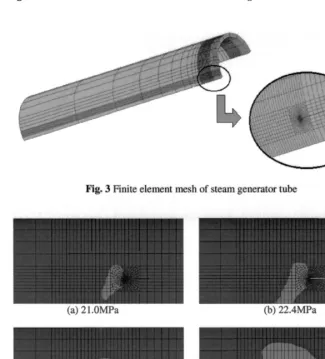
Fig. 3 shows the finite element mesh used in this study. A quarter of the tube was modeled using the symmetry and isoparametric 20-node reduced-integration brick elements. Finite element analyses were carried out for the cases
that the axial crack length, 2c, is equal to 8mm and the distance between two adjacent cracks, d, is equal to 1, 4, and
8mm, respectively. As the pressure increases progressively, the changes in COD (Crack Opening Displacement) and changes of plastic zones were observed in the mid-thickness of the tube wall.
Fig. 4 shows the change of plastic zone size for the case of 2c=8mm and d=4mm as the applied pressure increases. It is observed that plastic zones increase slowly up to 21MPa and contact at 22.4MPa. After the contact of plastic zones takes place, their size increases rapidly with a small amount of pressure increase. Plastic zones are formed larger in the inner section between cracks than in the outer area as expected due to interaction effects.
Once the contact pressure was determined, an equivalent single crack length was calculated using Eq. (1). That is, a single crack length which fails at the contact pressure was determined. Even though the plastic zone contact does not reduce the load carrying capacity of the uncracked ligament as much as in the collinear cracked case, it is assumed that the two parallel axial cracks can be converted into a single equivalent crack which is supposed to fail at contact
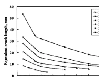
pressure. The calculated crack length using the foregoing process, 2Ceq, was shown in Fig. 5. It shows that the
equivalent crack length curves consist of two linear parts and all of them have inflection point at about 3 to 4mm in distance. When the distance is greater than 4mm the slope is gradual and vice-versa. The equivalent crack length approaches to the individual crack size when the distance between two cracks is far enough to neglect interaction effects. However, as two cracks come near the equivalent crack length increase more rapidly and this trend become more apparent as crack length increases. It can be estimated that two cracks merge into one crack when the two cracks approach and the distance is very small, so that the equivalent crack length in the case of very small separation should approach to a single crack length. In this regard, it seems that the proposed equivalent crack length overestimates interaction effects when cracks are closely spaced.
Since the proposed method overestimates the interaction effect for the case that two cracks are closely spaced, an investigation on the conservatism of this model was conducted using elastic-plastic finite element analysis with full stress-strain curve given in Fig. 6 [7].
In this study, both elastic analysis based on K and elastic-plastic analysis based on J-integration were carded out.
We defined the factors to explain the degree of interaction in elastic analysis and elastic-plastic analysis as [(ratio and
Jratio as follows, respectively.
K,.,,,io = K o (6)
JD
J ratio : ( 7 )
Js
where Ks and Ko are stress intensity factors for a single crack and two parallel cracks, respectively, and Js and Jo are
J-integrations for a single crack and two parallel cracks, respectively.
Table 2 shows the values of K,.,,tio when 2c=8mm and d= 1, 4, and 8mm, respectively. It is shown in Table 2 that
Kr,,tio increases as d increases. When Ko is less than Ks, the interaction produces a favorable effect and we call it
"negative interaction effect" (K,.aao < 1). Such negative interaction effect is getting more as the distance is getting
closer. These results are in a good agreement with Murakami's study for two parallel through-wall cracks [16] and
Cho's study for two parallel surface cracks [ 17]. Table 3 shows the values of Jratio when 2c=8mm and d= 1, 4, and 8mm,
respectively. Like Kratio, J,',~t~o also increases as d increases. The more negative interaction effects are observed for the
closer distance, and J,.aao shows greater negative interaction effects than K,.atio in all the cases.
From these results, it can be found that the longer and the closer cracks produce the more negative interaction effect. This is because the longer cracks develop the larger plastic zones and the closer cracks make two plastic zones the more easily contact. The study on interaction effects results in the conclusion that the approach based on plastic zone contact, unlike the collinear crack case, is not appropriate to determine the equivalent single crack due to exaggerated interaction effect when two cracks are closely spaced.
Failure Prediction Model Based on Crack Opening Displacement
According to the burst test results of steam generator tubes with multiple parallel axial cracks, the crack tip tearing and burst take place without ligament failure [18,19]. It is important to define an appropriate parameter that could be used for the failure prediction of the tube with two parallel axial cracks taking those observations into account. That is, an approach not based on ligament collapse is necessary. For this purpose, it was thought that the COD could be an appropriate candidate.
As the tube with two parallel axial through-wall cracks is deformed under the applied pressure loading, the COD
could be affected by two crack face displacements: opening in the circumferential direction (Uo) and in the radial
direction(U,.). The latter could be considered to contribute to Mode III failure, whereas the circumferential opening could cause the failure in Mode I. The difference between the sum in both directions and the circumferential displacement only is negligible, so that only the circumferential displacement is assumed to contribute to the tube failure and the CODs obtained from opening in the circumferential direction are considered hereinafter.
Finite element analyses for five single cracks of 2c=4, 6, 8, 10, and 14mm were performed and the changes of COD at the crack center, 80, were plotted as shown in Fig. 7. For the single crack case, the failure pressure could be determined from Fig. 1 with a given crack length. It was assumed that the failure of parallel cracks takes place when each COD value is equal to the COD obtained at the failure pressure of the tube with a single crack. The COD at the failure pressure for each single crack was indicated in this figure and marked with the symbol 'x'. The value was defined as the critical COD in this paper and denoted as (8o)crit. The following regression line was derived from the (8o)c,~, values.
((~o)crit = 24819P~ -3"44 (8)
where Pi is in MPa. The above power law expression was obtained using the least square fit of the data points indicated as 'x' in Fig. 7 and presented as dotted line. This curve can be used to determine critical COD value and the associated failure pressure for different cases with parallel axial cracks. The COD curves obtained from finite element analyses were plotted in Fig. 8 for four different crack lengths having a pair of parallel axial cracks varying in space in-between.
The failure pressure of each case could be, therefore, derived from the intersection point between the regression line and each COD curve. Fig. 9 shows that the failure pressures obtained from this procedure match well with those of single crack cases even for different separation of the pair cracks. We can recognize that the COD approach provide appropriate results even for the case the pair cracks are closely spaced. Putting the failure pressure into equation (1), the equivalent crack lengths could be determined. The 'negative interaction effect' is also confirmed in Fig. 10. When the pair cracks are closely spaced, i.e. d=lmm, the failure pressure of the pair cracks is greater than that of the
corresponding single crack in all four crack lengths. Fig. 10 shows the ratio of Po to Ps versus separation. The
shown in Fig. 10, the ratio approaches to 1 and the interaction effect comes to fade away if the pair cracks are separated greater than 12mm. This result seems to be consistent with that of the collinear crack case that interaction effects disappear when the separation distance between two collinear cracks is greater than 12mm. From the safety standpoint, the lower bound curve shown in Fig. 9 can be used to determine the allowable crack length for the multiple axial pair cracks in steam generator tubes for a given limiting pressure. That is, once the limiting pressure is
determined, the maximum allowable crack size, denoted by
2Ca,
could be determined from Fig. 9 using lower boundcurve for the case of parallel axial cracks whatever the separation distance is. Then, if the longer crack length of two
parallel axial cracks detected in a steam generator tube is greater than
2Ca,
it is unacceptable.CONCLUSIONS
A procedure applicable to determine the acceptability of the steam generator tube with multiple axial cracks was proposed by taking into account interaction effects of two adjacent cracks from the viewpoint of structural integrity.
The interaction effects of two collinear or two parallel axial through-wall cracks existing in a steam generator tube were investigated. For the former case a coalescence criterion based on limit load was proposed and a coalescence evaluation diagram was generated. This diagram could be used to determine whether the adjacent collinear cracks detected by NDE coalesce under a given pressure. Then the determined single equivalent crack will replace two collinear axial through-wall cracks.
For the latter case, the interaction effect considered to be more complicate was investigated using two approaches: one based on the plastic zone contact and the other based on COD. The former approach provides too conservative equivalent crack length when two parallel cracks are closely spaced. The investigation of interaction effects shows that a pair of axial cracks is less detrimental to structural integrity than a single crack when they are closely spaced. By taking into account the experimental observation that the crack tip tearing and burst in steam generator tubes with multiple parallel axial cracks take place without ligament failure, COD values were selected as an appropriate parameter to predict the failure pressure. It was assumed that the failure of the tube with parallel cracks takes place when each COD value is equal to the COD obtained at the failure pressure of the tube with a single crack. Once such critical COD is obtained, the failure pressure could be determined from Eq. (8) and the equivalent crack length can be calculated using equation (1). From the safety standpoint, the lower bound curve shown in Fig. 9 can be used to determine the maximum allowable crack length for the multiple axial pair cracks existing in steam generator tubes under the given limiting pressure.
REFERENCES
[ 1] USNRC, "NUREG/CR-6365, Steam Generator Tube Failures," April 1996
[2] USNRC, "Regulatory guide 1.121, Bases for Plugging Degraded PWR Steam Generator Tubes," August 1976
[3] ASME, "Rules for Construction of Nuclear Power Plant Components," ASME Code, Sec. III, 1998
[4] Cochet, B. and Flesch, B., "Crack Stability Criteria in Steam Generator Tubes," 9th Int. Conference on SMiRT,
Vol. D, pp.413-419, 1987
[5] Yu, Y.J., Kim, J.H., Kim, Y., and kim, Y.J., "Development of Steam Generator Tube Plugging Criteria for Axial
Crack," ASME PVP, Vol, 280, pp.79-83, 1994
[6] Gorman, J. A., Harris, J. E., and Lowenstein, D.B., Steam Generator Tube Fitness-for-Service Guidelines, AECB
Report No. 2.228.2, 1995
[7] Lee, J.H., Park, Y.W., Song, M.H., Kim, Y.J., and Moon, S.I., "Determination of Equivalent Single Crack based
on Coalescence Criterion of Collinear Axial Cracks," Nuclear Engineering and Design, Vol. 205, pp. 1-11,2001
[8] Kim, J.S., Han, J.H., Hwang, I.S., and Park, I.G, "Investigation Report for Steam Generator Tubes Pulled out
from Ulchin Unit 1," October, 1999
[9] Knag, S.C., Song, M.H., Kim, H.CL, and Kang, S.S., "Regulatory Technical Report on the Steam Generator
Tubes Safety of Nuclear Power Plants," KINS/AR-669, April, 1999
[ 10] Erdogan, E, "Ductile Failure Theories for Pressurized Pipes and Containers," Int. J. PVP, Vol. 4, 1976
[11] Kiefner, J. E, Maxey, W. A., Eiber, R. J., and Duffy, A. R., "Failure Stress Levels of Flaws in Pressurized Cylinders," ASTM STP536, pp.461-481, 1973
[12] Majumdar, S., Shack, W. J., Diercks, D. R., Mruk, K., Franklin, J., and Knoblich, L., "Failure Behavior of Internally Pressurized Flawed and Unflawed Steam Generator Tubing at High Temperatures - Experiments and Comparison with Model Predictions," NUREG/CR-6575, ANL-97/17, Mach, 1998
[ 14] Shibata, K., Yokoyama, N., Ohba, T., Kawamura, T., and Miyazono, S., "Growth Evaluation of Fatigue Cracks from Multiple Surface Flaws (I)," J. Japanese Nuclear Society, Vol. 27, No. 3 pp.250-262, 1985,
[15] Shibata, K., Yokoyama, N., Ohba, T., Kawamura, T., and Miyazono, S., "Growth Evaluation of Fatigue Cracks from Multiple Surface Flaws (II)," J. Japanese Nuclear Society, Vol. 28, No. 3, pp.258-265, 1986
[16] Murakami, Y., "Stress Intensity Factors Handbook," pp.204-205, 1987
[17] Cho, Y.J., "A Study on the Interaction Effect of Adjacent Semi-Elliptical Crack," Thesis for M.S., Sungkyunkwan University, 1990
[ 18] Framatome, "Steam Generator Tube Integrity," EPRI Report NP-6865-L, Vol. 1, 1991
[19] Argonne National Laboratory, "Steam Generator Tube Integrity Program," Monthly Pregress Report of ANL, April 3 & 28, 2000
Table I Specification of considered steam generator tubes [7]
Outer Diameter 22.22mm
Thickness 1.27mm
Material Inconel Alloy 600TT
Young's Modulus at 300°C 199.8 GPa
Yield Strength at 300°C 256.0 MPa
Tensile Strength at 300°C 656.0 MPa
Flow Stress at 300°(3 456.0 MPa
AP,,o,.,,u~l
10.2 Mpa[~kPacciaent
18.3 MPaTable 2 Evaluation of interaction effect based on K
Crack Size (ram)
Ks ( MPa.f'm )
Ko (MPa.f-m)
Kratio
45.50 0.7524
2c=8, d= 1 2c=8, d=4 2c=8, d=8
60.47 56.61 0.9362
1.0322 62.42
Table 3 Evaluation of interaction effect based on J-integral
Crack Size (mm)
2c=8, d= 1
2c=8, d=4
2c=8, d=8
P (MPa)
Js
(Mpa.m)Jo
(MPa.m)0.5795
5 0.2818 0.1633
10 1.681 0.9565 0.5690
13 3.458 2.024 0.5853
0.8804
13
5 0.2818 0.2481
10 1.681 1.411 0.8394
3.458 2.881 0.8331
13
1.071
5 0.2818 0.3019
10 1.681 1.797 1.069
4 0
~ z o
- - P a r t - t h r u c r a c k wlUt a f t = 0 . 4 - - T h r u - w a l l c r a c k
0 T h r u - w a l l c r a c k ( T e s t r e s u l t s b y F r a m a t o m e ) • T h r u - w a l l c r a c k
( T e s t r e s u l t s b y A N L )
. . . " , o
d I ! I I
10 2 0 30 40 50
C r a c k l e n g t h , m m
Fig. 1 Limit load solutions
1o
5
0 2 c = 2 m m [ [] 2 c = 4 n u n [
I A 2c--~mm I
O 2 c - - S m m ~ /%
, 2 c = l O m m ~ "~
• 2 c = 1 2 m m • 2 c = 1 4 m m • 2 c = 1 6 m m
U 2 c - - 1 8 m m ~ = ~
I I I I I
10 2 0 30 4 0 5 0
P i , M P a
Fig. 2 Coalescence evaluation diagram
'~ g
Fig. 3 Finite element mesh of steam generator tube
....
iiiili:'
(a) 21.0MPa (b) 22.4MPa
(c) 23.6MPa (d) 29.7MPa
60
50
}
, ° ,It~ 20
~.1 10
0 16
--~- 2c=2
I
--~- 2c=4 I --~ 2c--6 Ik - - - ~ c = l O l
~ + 2 c = 1 4 1
I I I I I I I
2 4 6 8 10 12 14 D i s t a n c e b e t w e e n c r a c k s , m m
Fig. 5 Equivalent crack length of two parallel cracks
o 2c--atom ** i
2c--6mm ~ : .
* 2c=10nun " '. ** 8
2c=14mm
v~ . . . t ': : i
...-~.~...,o.,. : , i , .
' ~ I;I
/1 "'/+ /
/
(8.)erit = 24819P1" ,*4 l' J / ..
,/'" ...,.."o;,.../,
/
i ~ : ~ " , % ,<'"o ,~<><', ° ,° °°,+° , , "
5 lo 15 lo 25 30 3~ 40 45 50 55
Pi, M P a
Fig. 7 Changes of COD at the crack center
1000
8 0 0
600
400
200
I 0.3
~ 0.2
- - E n g . Stress - Eng. Straht [ . . . . Tllle Stress - True Stl~hl ... -
o o
I I I I
0 0.1 0.2 0.3 0.4 0 . 5 S t r a i n
Fig. 6 Stress-strain curve used in the analysis of interaction effects
- - s h , ¢ . crack ] ',
11 l;'ailm-e pressure [ ,
of a single crack I ', ~ o 6 l l " ~ t '
'+
:!iJ/
z //i4
}//i
0 $ 10 15 20 25 30 35 40 45 50 $5
Pi, M P a
Fig. 8 Changes of
(AUo)z=O
4O
{II
30
20
0
Single c r a c k . d = 4 m m o d = 6 m m - - . - , ~ • d = S m m " ' - . ' ~ A d = 1 0 m m
" . . A - ~ + d= 1 2 m m • . , . " ~ . . . L o w e r b o u n d
" - . . . ~ . - - £ U l - ¢ e
"-+..~~
! ! I
1.2
l . I
1.0
0.9
0.8
0.7
4 8 12 16
2 ¢ j m m
Fig. 9 Failure pressures of double cracked tubes
• 2 c = 4 n n n 4, 2 c = 6 m m t 2 c = S m m m 2 c = 1 0 m m
. . . .
I I I l I I
2 4 6 8 10 12
d , m m
![Table I Specification of considered steam generator tubes [7]](https://thumb-us.123doks.com/thumbv2/123dok_us/1726099.1220229/6.596.107.433.193.333/table-i-specification-of-considered-steam-generator-tubes.webp)