Horizontal Strut-Arm Optimization Effects on Drag Coefficient
Full text
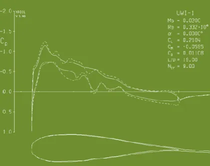
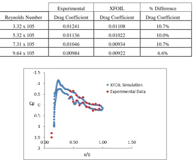
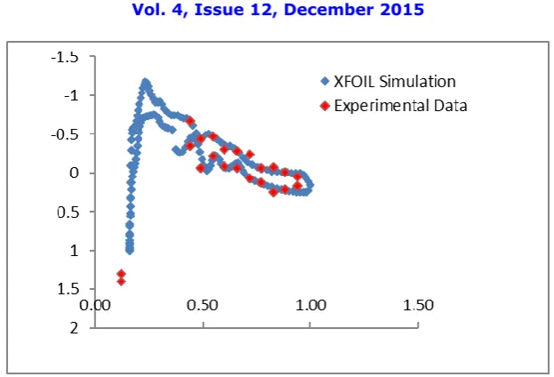
Figure


Related documents
raised: 1) to study the interaction and heterologous IVF parameters using dolphin spermatozoa and zona-intact cow and murine oocytes; and 2) to study sperm maturation,
Next, we present in detail our approach for ex- tracting the coherent movement in different locations on the face from dense Optical Flow method by filter- ing the noise on the basis
Goals Controlled Mild Good 0°-110° Good None < 3 mm Frequency 3-4 x/day 10 minutes 3 x/day 15 minutes 3 x/day 5 minutes 1-2 x/day 5 minutes As required Range
VTR235107 M3 x 10mm Button Head Screw M3 x 10mm Halbrundschrauben Vis à tête bombée M3 x 10mm Viti testa tonda M3 x 10mm VTR235110 M3 x 16mm Button Head Screw M3 x
24) Three times the sum of a number and 3 is 3 less than the number times 5. Find the
Remove the lower bolt that attaches to the control arm and the 3 nuts that attach the strut to the upper strut mount.. Do NOT remove the center nut that holds the strut
pling procedures were achieved: (i) Sampling of fodder, camel raw milk and shubat (fermented camel milk) in 8 farms closed to pollution sources from the South of Kazakhstan for
The New Jersey Medical School National Tuberculosis Center (NTBC) and NJ State TB Program staff held follow-up discussions with selected SATFs and local health departments to
