(Under the direction of Dr. Trevor J. Little).
This body of research seeks to improve the design and development of a class of products referred to as engineered designs. Specifically, the process for textile design engineering within the shape of a product. Textile Design Engineering within the Product Shape is an iterative and often highly collaborative design process. The purpose of this type of engineered design is to i) improve the performance of the product and/or, ii) to improve the aesthetics of the design. Products engineered for aesthetic purposes can create a seamless design by continuing a motif or fabric structure across a seam, dart or closure, and accentuate shape or movement. Products engineered for functional purposes can improve performance, comfort, fit, and movement, reduce waste, and reinforce areas of high wear.
Expert practitioners from industry, academia, and research institutes were surveyed on their use of engineered design. In addition, case study analysis was conducted on the engineered design process. Results from the survey and case study analysis assisted with building a four stage process model. The research uncovered a need for increased input from designers and the need for improved communication and collaboration between members of design and product development teams. New and emerging technologies such as digital printing, integral knitting, and 2D and 3D simulation software facilitate the engineered design process; however, these technologies are underutilized.
by
Lisa Parrillo Chapman
A dissertation submitted to the Graduate Faculty of North Carolina State University
In partial fulfillment of the Requirements for the degree of
Doctor of Philosophy
Textile Technology Management
Raleigh, North Carolina October 31, 2008
APPROVED BY:
_______________________________ ______________________________ Dr. Trevor J. Little Dr. Traci Lamar
Committee Chair
DEDICATION
BIOGRAPHY
ACKNOWLEDGMENTS
I wish to acknowledge the time and expertise that was contributed to this body of research by members of academia, industry, and research institutes in the field of textile design engineering. Survey and case study participants provided intelligent, thoughtful observations and opinions about this design process, and were generous in sharing their experiences with engineered designing. I also want to acknowledge the support of the College of Textiles, and TATM department for funding my graduate studies, and providing access to state of the art facilities in which to conduct my research. I am sincerely grateful to Dr. Lori Rothenberg for provided guidance in survey analysis, and to Dr. Helmut Hergith who assisted with translation from German to English for one of my case study interviews.
I would like to extend my appreciation to TC2, for their assistance with engineered design and digital printing, and to Cotton Incorporated who allowed me to interview their clients. I am grateful for the assistance that Hari Kenkare, my friend at Lectra, provided with access to software programs. Thank you also to my friend Ji-Hyun Bae, for her assistance with woven and printed engineered design.
TABLE OF CONTENTS
LIST OF TABLES ... viii
LIST OF FIGURES ... ix
1. INTRODUCTION ... 1
1.1. Purpose of Research ... 3
2. LITERATURE REVIEW: TECHNOLOGIES SUPPORTING ENGINEERED DESIGN .... 4
2.1. Digital Printing ... 5
2.1.1. Global Print Market ... 5
2.1.2. United States Print Market ... 8
2.1.3. Machine Technology ... 9
2.1.4. Dye Formulation and Market ... 15
2.1.5. Sampling and Strike-Offs ... 19
2.1.6. Small Production Runs ... 23
2.1.7. Mass Customization ... 26
2.1.8. Engineered Print Design... 29
2.2. Integral Sweater Knitting ... 35
2.2.1. Market Overview ... 35
2.2.2. Machine Technology ... 39
2.2.2.1. Weft Knitting: Straight and Flat ... 40
2.2.2.2. Weft Knitting: Circular Strip and Bodysize ... 44
2.2.3. Shaping Methods ... 45
2.2.3.1. Wale Fashioning ... 46
2.2.3.2. Needle Selection Shaping ... 47
2.2.3.3. Reciprocal Shaping ... 49
2.2.4. Construction Processes ... 50
2.2.4.1. Cut and Sew ... 53
2.2.4.2. Fully Fashioned... 55
2.2.4.3. Assembly ... 57
2.2.4.3.1. Overlock ... 58
2.2.4.3.1. Linking ... 59
2.2.4.3.2. Cup Seaming ... 60
2.2.4.4. Integral Knitting ... 61
2.2.5. Coloration ... 66
2.2.5.1. Yarn Coloration ... 67
2.2.5.2. Striping ... 68
2.2.5.3. Jacquard ... 69
2.2.5.5. Garment Coloration ... 72
2.2.6. Computer Aided Design ... 74
2.3. State of the Art in Engineered Designing... 76
2.4. Review of Models ... 79
2.4.1. Macro View ... 79
2.4.2. Micro view ... 85
2.5. Summary of Literature Review ... 87
3. RESEARCH METHODOLOGY ... 93
3.1. Research Objectives: ... 95
3.1.1. Stage One Objective: Develop a Base Model for Engineered Designing .. 96
3.1.2. Stage Two Objectives: Refine Model, Validate Definition, Test Theory .... 96
3.1.3. Stage Three Objective: Validate Model ... 97
3.2. Stage One Procedure ... 97
3.3. Stage Two Procedures: Survey of Engineered Design Experts ... 99
3.3.1. Survey Development... 99
3.3.2. Stage Two: Data Collection ... 104
3.4. Stage Three Procedures: Multiple Case Studies ... 107
3.4.1. Case Study Protocol ... 108
3.4.2. Case Study Selection ... 110
3.4.2.1. Case Study One: Engineered Print Design ... 111
3.4.2.2. Case Study Two: Engineered Knit and Print Design ... 111
3.4.2.3. Case Study Three: Engineered Knit Design ... 112
3.4.2.4. Case Study Four: Engineered Woven Design ... 112
3.4.3. Stage Three: Data Collection ... 112
4. RESULTS ... 114
4.1. Stage One Results... 114
4.1.1. Narrowing of the Object of Study ... 118
4.1.2. Model building ... 119
4.1.3. Theory building ... 123
4.2. Stage Two Results ... 124
4.2.1. Definition of Term ... 124
4.2.2. Theory Testing ... 127
4.2.2.1. Theory I Results ... 128
4.2.2.2. Theory II Results ... 135
4.2.2.3. Theory III Results ... 138
4.2.3. Model Refinement ... 145
4.3. Stage Three Results ... 149
4.3.1. Case Study One (AP1) Input to Model ... 150
4.3.1.1.2. Communication ... 153
4.3.1.1.3. Implementation ... 157
4.3.1.1.4. Iteration ... 159
4.3.1.1.5. Assessment ... 159
4.3.1.1.6. Special Concerns ... 160
4.3.2. Case Study Two (AKP2) Results: Input to Model ... 161
4.3.2.1. Generation ... 163
4.3.2.2. Communication ... 164
4.3.2.3. Implementation ... 164
4.3.2.4. Iterations ... 167
4.3.3. Case Study Three (FK3): Input to Model ... 168
4.3.3.1. Generation ... 170
4.3.3.2. Communication ... 170
4.3.3.3. Implementation ... 171
4.3.3.4. Iteration ... 174
4.3.3.5. Special Concerns ... 176
4.3.4. Case Study Four (FW4): Input to Model ... 178
4.3.4.1. Generation ... 180
4.3.4.2. Communication ... 180
4.3.4.3. Implementation ... 180
4.3.4.4. Assessment ... 181
4.3.4.5. Iterations ... 183
4.3.4.6. Special Concerns ... 183
4.4. Model Analysis ... 184
4.4.1. Design Generation ... 185
4.4.2. Design Communication ... 186
4.4.3. Design Implementation ... 187
4.4.4. Design Assessment ... 187
5. FINAL ANALYSIS: SUMMARY, CONCLUSION, AND RECOMENDATIONS ... 189
5.1. Summary ... 189
5.2. Conclusions ... 191
5.3. Recommendations ... 196
REFERENCES CITED ... 198
APPENDICES ... 211
APPENDIX A ... 212
LIST OF TABLES
Table 1. Original Machine Manufacturers ... 13
Table 2. Machine by Print Head Type (Tyler, 2005) ... 15
Table 3. Ink Systems (Presgrave & Provost, 1996) ... 18
Table 4. Particle Size by Colorant (Kiatkamjornwong et al., 2005) ... 19
Table 5. Costs for Sampling (Noonan, 2003) ... 21
Table 6. Comparison of Production Steps for Sweater Construction (Brackenbury, 1992) ... 52
Table 7. Textile and Apparel Product Development Models ... 84
Table 8. Summary of Survey Instrument ... 103
Table 9. Case Study Tactics to Test Validity of Results (Yin 2003) ... 109
Table 10. Summary of Textile and Apparel Software Review ... 117
Table 11. Development of Propositions ... 125
Table 12. Participants‟ Agreement that Virtual Prototyping Would Aid Engineered Design ... 141
Table 13. Summary of Case Study AP1 Results ... 151
Table 14. Summary of Case Study AKP2 Results ... 163
Table 15. Summary of Case Study FK3 Results ... 169
LIST OF FIGURES
Figure 1. Digital textile placements by technology (Byrne, 2004) ... 9
Figure 2. Classification of ink jet printing technologies (Tyler, 2005) ... 10
Figure 3. Extending color gamut with additional colors (Sarma, 2004) ... 17
Figure 4. Screen Printing and Digital Ink Jet Printing Production Routes ... 24
Figure 5. Small run advantages (provided by DuPont Industries) ... 25
Figure 6. Mass customization advantage (Anderson, 2003) ... 26
Figure 7. Engineered Print Design (L. P. Chapman & Istook, 2002) ... 31
Figure 8. Examples of Engineered Print Design ... 33
Figure 9. OTEXA Import Value of Knitted Apparel by Product Category (OTEXA reference.2007) ... 39
Figure 10. Weft knitting machine classifications and shaping and production capabilities ... 42
Figure 11. Stitch shaping examples ... 46
Figure 12. Primary sweater construction methods (Brackenbury, 1992) ... 51
Figure 13. Diagram of separator thread insertion for garment knitted length... 54
Figure 14. Calculation of a fashioning frequency. (Raz 1991) ... 56
Figure 15. Examples of overlock seaming problems ... 59
Figure 16. Hague 420 linking machine ... 60
Figure 17. Tubular method for complete garment knitting ... 62
Figure 18. Stoll‟s Gore Technique for complete garment knitting . (Hunter, 2005) ... 64
Figure 19. Knitwear design process (Eckert, 2001) ... 66
Figure 20. Sweater Coloration and Finishing Processes ... 67
Figure 21. Examples of sweaters knitted with dyed yarn ... 68
Figure 22. Jacquard Float compared to Jacquard Pique ... 70
Figure 23. Example of Intarsia Knitting ... 72
Figure 24. Three dimensionally printed fabric structures (Kyttanen, 2007) ... 77
Figure 25. Examples Laser Sintered Items ... 78
Figure 26. The spiral model (Boehm, 1988) ... 81
Figure 27. Conceptual model of the relationship between design of experiment for product design versus other disciplines (Owen, 1998) ... 95
Figure 28. Summary of textile and apparel design software capabilities... 115
Figure 29. Initial model developed to show areas where engineered design placement of coloration within a product can occur. ... 120
Figure 30. Engineering of yarn coloration for knits using the Propoli printer ... 122
Figure 31. Proportion of identified experts who agree with the author‟s proposed definition. ... 127
Figure 32. Additional time needed for an engineered design ... 130
Figure 33. Additional cost needed to produce an engineered design ... 132
Figure 34. Participants who responded that an engineered design requires more collaboration and centralization than a non-engineered design ... 133
Figure 35. Comparison of expert response rates of time, cost, collaboration, and centralization 134 Figure 36. Rating Average for Level of Difficult with Engineered Placement ... 136
Figure 37. Rating Average for Level of Difficulty for Engineering a Textile Design ... 137
Figure 39. Percentage of partcipants who use virtual, non-virtual, or both virtual and non-virtual
prototyping. ... 142
Figure 40. Mosaic plot of the use of virtual (V), virtual (V), or a mix of both virtual and non-virtual (M) prototyping processes, categorized by woven, knitted or printed design ... 143
Figure 41. Reason Cited for Not Using 3D Visualization Software ... 144
Figure 42. Primary Purpose for Creating an Engineered Design ... 146
Figure 43. Process model for an engineered design. ... 148
Figure 44. High level process model for design of an engineered textile product ... 149
Figure 45. Process for placement of motifs within a garment shape ... 155
Figure 46. Design consultant‟s storyboard rendering of the product idea. ... 171
1. INTRODUC TION
The most time consuming and resource intensive part of the production of textile products is the product design and development cycle. Even after considerable time and resources are allocated to development, the product can be rejected for a number of reasons, such as i) it is not technically feasible to manufacture the item, ii) it is too expensive to produce the item, iii) it is too time consuming to manufacture the item, iv) the item is not aesthetically pleasing, and/or v) the item is not appropriate for the intended market. If the product is rejected, the product design and development process starts over.
Integration of some or all of the fabric design process with the final product development process can improve prototyping, and consequently the end product can be improved. Typically a textile designer produces the fabric that is then chosen by an apparel or home furnishings department for use in the end product. Fabric is not always designed for an intended end product and vice versa, an end product is not always developed with a fabric in mind. The typical process demands that a product developer search for and then test fabric that will be appropriate for the end use of the product (Brown & Rice, 1998). However, if the fabric and end product are designed simultaneously, i.e., if some or all of the fabric design properties are engineered for the end product, then aesthetic and functional aspects of the product are improved.
ii) to improve the aesthetics of the design. Products engineered for aesthetic purposes can hide seams, accentuate shape or movement, divert attention from an area of the body, or continue a motif or pattern across a seam, dart or closure. Performance engineered design can reinforce areas of high wear, reduce waste, or improve comfort and fit. For example, to improve performance, a sweater could be engineered to have a more elastic structure knitted into areas of high stress. In contrast, a print design with a large, central motif that is strategically placed on the garment to accentuate the body would be considered an engineered design for aesthetic purposes.
these technologies are geared toward aesthetic visualization, they may also aid in the strategic placement of functional factors.
1.1. Purpos e of R es earch
2. LITER ATURE R EV IEW: T EC HNO LOGIES SUPP ORT I NG ENGINEERED DES IGN
2.1. Di git al P rin ting
The textile print market is robust, but it is also a swiftly changing market and one that is strongly affected by fashion trends. Ink jet printing, a developing technology for the print market, has the capacity to more quickly respond to changing trends. Ink jet printing filled a need in the market for a more cost effective and faster sampling process, a direct result of consumer demand for more variety of prints in the market. The continued support and development of ink jet printing are dependent on varied and interdependent, factors. Push factors such as improved dye chemistry and machine engineering could eliminate fabric pre-treatment and post treatment and allow for increased print speeds. Continued research and development activity and funding will help to improve and continue innovation in ink jet printing. While educational support provided by professional, and research organizations will insure that ink jet printing is optimally used in the product design process. But most likely it will be consumer demand for customized and novel prints and more variety of prints that will pull the market.
2.1.1. Global Print Market
these three categories printing is used for carpet and automotive design, labels for garments and for signage.
By far, the largest end use for printed goods worldwide is for the Apparel sector which accounts for, on average, 54% of all printed goods. In Asia, Africa, Western and Eastern Europe 50% of each region‟s printed fabric is for the garment industry. In fact, in Asia where more than half of the world‟s printed fabric is made, more than 70% of the printed goods are for apparel (Teunissen, Kruize, & Tillmanns, 2002). The majority of printing is done on fabric lengths but garment printing is gaining momentum largely due to demand for printed t-shirts; which has now grown to a $20 billion business within the United States alone (Williams, 2006).
Worldwide, printed interior textiles comprise 30% of the textile print market; nine million square meters are printed annually (Byrne, 2004). Interior textiles, or home furnishings, include bedding, upholstery, carpet and decorative accents such as mats and pillows. In the U.S., 50% of printed production is for interior textiles, a larger market segment than that of apparel which makes up 30% of the market. Although print production for apparel and interior fabric has declined in North America, the percentage of printed fabric for technical textiles has increased to 20% of all printed goods. The global market reflects similar growth; on average there has been a worldwide increase in technical textiles (Teunissen et al., 2002).
about .01% is estimated to be printed via an ink jet printer (Teunissen et al., 2002). In 2002 the annual worldwide growth was estimated at 13% (Cahill & Ujiiie, 2004). However, I.T. Strategies, a consulting firm specializing in the ink jet printing market, states that in 2005, ink jet printers printed 71 million square meters - a larger growth than anticipated. Asia has experienced the largest growth in print production, not surprising considering that the majority of the world‟s printed fabric, more than 50%, is produced in this region. This has proved detrimental to other regions, for example, although Africa and Latin America have experienced modest growth, all other regions such as North America, Eastern and Western Europe, and the Middle East have all seen declines in their production of printed goods. Worldwide, printing tends to be a localized market, on average 63% of printed textiles are produced for a region‟s own market. The exception to this is Asia, that region exported 57% of their printed goods in 2001 (Teunissen et al., 2002).
the decline is continuing (Teunissen et al., 2002). Overall the average number of colors per print design has remained constant at six. However, the largest print producer, Asia, has seen an increase in number of colors per design, from 6 in 1994 to 7.3 in 2001 (Teunissen et al., 2002). This is mainly because of the demands from Asia‟s markets, namely North America and Europe, which call for higher quality and more fashion forward prints, which translate to an increase in colors and variety of prints. More variety in prints equals more runs, but with shorter run lengths.
2.1.2. United States Print Market
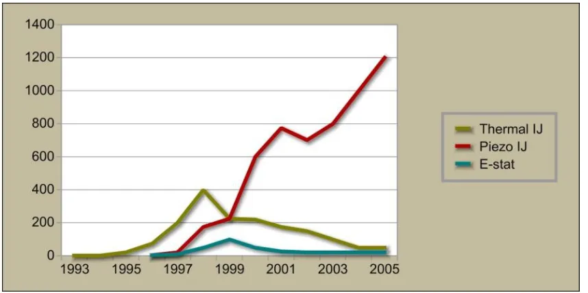
An industry survey from 1984 found 23 firms in the U.S. who had printing facilities. More than half of these firms were located in the southern states with an average size of 51 to 100 employees. The majority of the printing companies used rotary screen printing (34%) followed by roller printing (12%), heat transfer (11%) and flat bed (8%) (Amidon, 1991). Information from the printing survey states that the 1984 U.S. Department of Commerce‟s Current Industrial Report included detailed information on print production facilities such as geographic location, method of printing and whether the firm was a commission or non- commission printer. The time from the late 1980s until the early 1990s was a period of strong economic growth for the U.S. printing industry but from 1994 to 1997, U.S. printed fabric production dropped 20%, one of the severest downturns of print volume in U.S.‟s history (Byrne, 2004) 1
. It is not a
1
coincidence that during this economic downturn the textile printing industry had a marked increase in the number of ink jet printers placed in production (see Figure 1).
Figure 1. Digital textile placements by technology (Byrne, 2004)
2.1.3. Machine Technology
being piezo followed by bubble jet and with valve operated the slowest (Dawson, 2000).” While the method of ejecting the ink drop varies by type of print head, all three print heads form the same type of ink drop; the dye is forced from the print head forming a tail, the ink tail collapses onto its head forming a sphere and the spherical ink drop strikes the fabric. The size of the ink drop can vary considerably, from 50 to 1000 picolitres (T. L. Dawson, 2001).
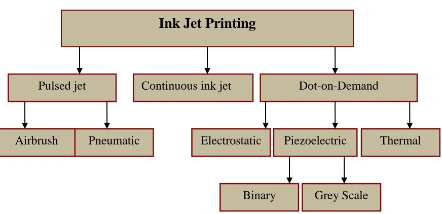
Figure 2. Classification of ink jet printing technologies (Tyler, 2005)
In 1878 Lord Rayleigh devised a method for breaking up a stream of ink into smaller droplets (Rayleigh, 1878). It was not until 1952 though that the first patent for an ink jet mechanism was filed by Elmqvist an employee of Seimens (Elmqvist, 1951). In the 1960s Dr. Sweet, from Stanford University, broke the ink jet stream into droplets using a pressure wave valve and proved that by applying an electrical charge to the ink
Pulsed jet Continuous ink jet Dot-on-Demand
Electrostatic Piezoelectric Thermal Airbrush Pneumatic
drops the drop size and formation could be controlled (Sweet, 1965). IBM acquired Sweet‟s continuous ink jet technology in the 1970s and in 1976 launched the IBM 4640, the first low cost ink jet printer (Le, 1998). Home and office use of computers began to rise in the 1950s through the 1970s, and the need for printers increased as consumers demanded the ability to print data generated from the new computers (Webster, 2000). As computers sales increased and the cost of ink jet printers decreased sales of printers skyrocketed - from 30,000 units sold in 1960 to over 50 million units sold in 2000 (Webster, 2000).
A subset of ink jet printers is the large format ink jet printer, defined as any printer with a print width larger than an A2 size paper or 594 mm by 420 mm. (Presgrave & Provost, 1996). Large format printers are used by the graphics art industry and for sign and banners. Although a smaller market than desktop printers the large format market has shown a steady increase. By the mid 1990s, worldwide, the paper printing industry had 15,000 units of large format ink jet printers installed and in 2004 over 130,000 wide formats printers were in use (Williams, 2002).
physically handle printing a roll of fabric, but the print heads were not designed for textile inks. What was missing was the ability to print with textile specific inks so that the printed fabric would have the same fastness properties as screen printed samples.
Table 1. Original Machine Manufacturers
Company name Country of origin
Original machine supplier
Dua Graphic Systems (DGS) Italy Mimaki
Digital Printing Systems (DPS) USA Mimaki, Reggiani
Dupont Ink Jet USA Inchinose, Vutek
Gali Internacional Spain Roland, Mutoh
La Meccanica Italy Mimaki
Macchine e Servizi (MS) Italy Mimaki, Roland
Spuhl Switzerland L&P Digital
Stork Digital Imaging Netherlands Mimaki, Konica
inks used for textile printing require up to 15% more colorant than inks for paper printing (Geisenberger & Zeller, 2000).
* Have their machines modified and sold-on by other companies
2.1.4. Dye Formulation and Market
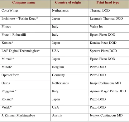
In order for ink jet printed fabrics to be marketable they must have the same as or better properties than screen printed textiles already on the market. A good quality print is dependent on the interaction between ink and print head; mainly the ability for the print head to remain unblocked by the inks (T. L. Dawson, 2001). In addition the inks must Table 2. Machine by Print Head Type (Tyler, 2005)
Company name Country of origin Print head type
ColorWings Netherlands Thermal DOD
Inchinose – Toshin Kogo* Japan Lexmark Thermal DOD
Filteco Italy Valve Jet
Fratelli Robustilli Italy Epson Piezo DOD
Konica* Japan Konica Piezo DOD
L&P Digital Technologies* USA Spectra Piezo DOD
Mimaki* Japan Epson Piezo DOD
Mutoh* Belgium Piezo DOD
Optotexform Germany Piezo DOD
Osiris Netherlands Imaje Continuous MD
Reggiani * Italy Aprion Magic Piezo DOD
Roland* Japan Piezo DOD
Vutek* USA Piezo DOD
remain stable, the printed fabric must have approved fastness properties and the correct target color must be achieved (T. L. Dawson, 2001).
Achieving the correct color in ink jet printing is a complex process. There are major differences between ink jet printing and screen printing in how each achieves color. In screen printing spot colors are used, while ink jet printing uses process color. A spot color is mixed to its exact shade, using any number of required colors, every time a new pattern is printed. Process color is laid down in a dot matrix pattern from a set of fixed colors (anywhere from 6 to 12). The color effect is much like pointillism as the dots visually blur together or mix to form other colors. For instance to form green, tiny dots of yellow and blue would be laid down side by side or overlapping each other. These dots are not randomly placed rather they are dropped within a matrix pattern so as to appear random.
comprised of the typical four cartridges, each containing full strength solutions of cyan, magenta, yellow and black but then anywhere from two to four additional cartridges are added that are made up of half strengths solutions of dye. Using a hi/lo set of inks will extend the number of shades but will not extend the limits of the gamut. As shown in Figure 3, in order to extend the limits of the gamut (number of colors) an additional dye color such as a brighter orange red or reddish blue or violet can be added to the ink set (T. L. Dawson, 2000).
Figure 3. Extending color gamut with additional colors (Sarma, 2004)
be marketable they need, at the minimum, the same properties as conventionally printed fabrics. The various ink systems available for textile ink jet printing are shown in the Table 3.
Table 3. Ink Systems (Presgrave & Provost, 1996)
Aqueous Dyes Aqueous
Dispersion
Solvent Based Dye
Non Aqueous Dispersion
Direct Pigment Solvent Soluble Pigments
Acid Disperse
Reactive Vat
Although the density was superior for ink jet printing it took three passes to obtain the density of color as for screen printing. Additionally it was found that the gamut volume of treated fabric is higher or much better than those fabrics that are not pre-treated and also of screen printed fabric. Another factor that affected the print quality was the penetration of ink. More colorant is used for ink jet printing and the colorant used is more aqueous therefore ink penetration is increased. This causes shifts in the printed hue, a reduction in saturation, and a smaller printed color gamut.
2.1.5. Sampling and Strike-Offs
Sampling onto textiles is at present the largest market use for textile ink jet printers. I.T. Strategies, a U. S. based consulting firm for digital printing, defines textile print sampling as a process for printing on paper or textiles for accurate reproduction of a screen printed fabric. A Strike-off is described as “producing a sample of single, saleable items for markets such as luxury, entertainment or special events (Ross,
Table 4. Particle Size by Colorant (Kiatkamjornwong et al., 2005)
Colorant Particle Size
Cyan 98nm
Magenta 200 nm
Yellow 177 nm
Black 132 nm
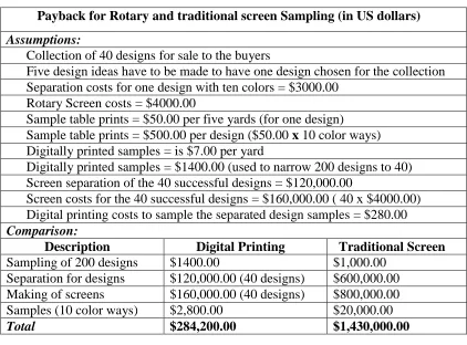
2000).” Traditionally sampling has been a very time consuming and costly part of the process of bringing a new design to market. In 2001 DuPont estimated that to produce the screens needed to print one new textile pattern containing six to eight spot colors costs between $4,000.00 and $8,000.00 (U.S.) dollars (Ross, 2000).
Table 5. Costs for Sampling (Noonan, 2003)
Payback for Rotary and traditional screen Sampling (in US dollars) Assumptions:
Collection of 40 designs for sale to the buyers
Five design ideas have to be made to have one design chosen for the collection Separation costs for one design with ten colors = $3000.00
Rotary Screen costs = $4000.00
Sample table prints = $50.00 per five yards (for one design) Sample table prints = $500.00 per design ($50.00 x 10 color ways) Digitally printed samples = is $7.00 per yard
Digitally printed samples = $1400.00 (used to narrow 200 designs to 40) Screen separation of the 40 successful designs = $120,000.00
Screen costs for the 40 successful designs = $160,000.00 ( 40 x $4000.00) Digital printing costs to sample the separated design samples = $280.00 Comparison:
Description Digital Printing Traditional Screen
Printing Sampling of 200 designs
iaideasideas
$1400.00 $1,000.00
Separation for designs $120,000.00 (40 designs) $600,000.00 Making of screens $160,000.00 (40 designs) $800,000.00
Samples (10 color ways) $2,800.00 $20,000.00
Total $284,200.00 $1,430,000.00
jet printer, costs for sampling are reduced by up to 80% (RocSearch, 2005). Blumenthal print works, a weaver and printer of jacquard damask that services the home furnishings and decorative fabrics industries, purchased an ink jet printer in 1999 for sampling and within two weeks the cost of printer was recouped (I.T. Strategies, 2006b).
In 2002, Jerry Bruce from Cone Finishing (a division of ITG, the International Textile Group) described the job of a commission printer as interpreting the ideas or artwork of the fashion designer. He states that this is a difficult process because often the artwork does not lend itself to the current process of screen printing and therefore is not always interpreted by the converter correctly. Most often the sampling process is done not once but many times. Cone typically produced 1,000 to 1,200 prints each year and each design averaged 14 colors. If five color ways are requested, the sampling process would involve 70 screen lay downs per design (Isaacs, 2002). However, this does not guarantee that the consumer will like and purchase the product; it only increases the chances that the designer will approve it. Savings in cost are not the only advantages to sampling via ink jet printing, savings in time are also substantial. Sampling by rotary, flat and other screen printing methods accounts for more than 50% of the time needed to produce a printed fabric. While the approval of samples done by screen printing can take six to eight week or longer, sampling by ink jet printing can take hours. This greatly reduces the overall time to produce a print as seen in Figure 4 (Choi, Yuen, Ku, & Kwan, 2003).
market. Stork recently developed a sampling system called Stork-U-See. Samples can be produced in their print bureau in Thailand or customers can set up ink jet printing systems in house using Stork‟s hardware, software and consumables. Following the procedures advised by Stork guarantee that samples will match production screen printing (Van der Meij, Jorg, 2005).
2.1.6. Small Production Runs
Finding an economical means of printing less than 1,000 yards has always posed a challenge for those manufacturers in small or niche markets, or for startup companies. Gild the Lily, a partnership between Jacqueline Rice (the former Dean of Fine Arts at Rhode Island School of Design) and Uosis Juodwalkis (owner of a photography, signage and color business) takes advantage of the small run capabilities of ink jet printing. Founded in 1998, the business sells one a kind and limited edition apparel. Juodovalki says that “We need to be inventive and produce in small quantities and this is where we have an advantage using ink jet” (I.T. Strategies, 2006b).
2.1.7. Mass Customization
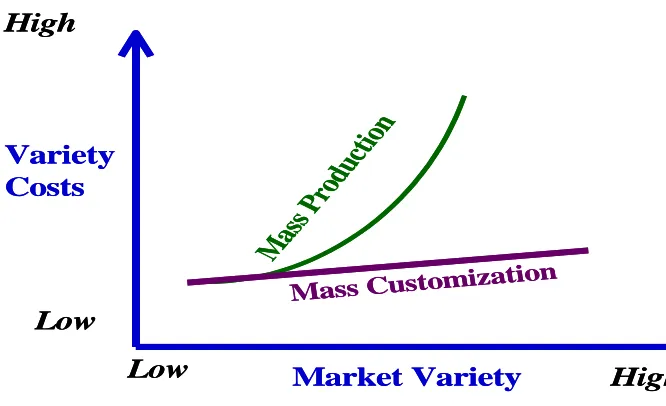
Consumer demand for shorter and more varied fashion cycles forced manufacturers to shorten the prototyping process. Adopting inkjet printing for sampling significantly reduced the product development cycle. Using ink jet printing for sampling led to short run production. A natural progression then occurred from short run production to mass customization. Mass customization is defined by Anderson and Pine as “the ability to design and manufacture customized products at mass production efficiency and speed” (Anderson, 2003). Dr. Anderson, a pioneer of mass customization, states that mass production thrives when the market is stable and there is a low consumer demand for a variety of items. As market variety increases and the market becomes more volatile, mass production methods are less feasible due to increasing costs (see Figure 6).
Figure 6. Mass customization advantage (Anderson, 2003)
M
as
s P
ro
du
ct
io
n
Variety
Costs
Mass Customization
Low
High
Low
High
Market Variety
M
as
s P
ro
du
ct
io
n
Variety
Costs
Mass Customization
Low
High
Low
High
Demand from the consumer for more variety of fashion prints would shorten the print run making ink jet printing cost effective. The ability to print on demand with no difference in cost between one or one thousand yards has led to the adoption of ink jet printing for a multitude of mass-customized products. For example, CS Fabrics Inc., founded by Robert Polk (a quality control engineer) and Gina Polk, (a textile artist) have incorporated a mass customization model into their business plan. As well as providing printing services for sampling and small runs, the owners designed a website for customized fabrics. Customers are able to browse a library of textiles design patterns created by various artists. Working directly with the artists, customers can make changes in color, scale, etc. (Enabling textile creativity: Fabric with S.P.A.
TM
.2005). The Polk‟s targeted the interior design business with their S.P.A. approach: Select a fabric type, Pick a pattern and Assign colors. “Current costs for custom fabric
common is simple construction and design so that customers are not flooded with choices.
One of the market sectors to use ink jet printing successfully for customization is the garment printing industry. Both t-shirt and sweater printing machines are available and are being used to allow customers to purchase customized clothing. In 1993 the first t-shirt printer was developed by Embleme as a result of a French government sponsored project. The machine looked like a t-shirt printing machine, however it used UV curing technology. Industrial print heads had UV lights attached to cure the ink as it was printed. Currently the United States‟ t-shirt industry is valued at over 20 billion dollars (Williams, 2006). Rich Hoffmann from M&R Sales and Service Inc. is a 25 year veteran of the t-shirt printing business. In 2004 he estimated that T-shirts sales are increasing at a rate of eight to ten percent. The demand for more complex designs is also increasing; in the late 1990‟s the average of number colors required for a screened t-shirt design rose from eight to eighteen, similar to what is happening in the textile sampling market.
Ink jet printing directly onto textiles fits in well with specialty markets. It offers two advantages without an increase in cost: the option to print small runs for unique or one of kind designs, and the ability to print an unlimited number of colors. Girly Chic Inc., a boutique located in Los Angeles, CA, and owned by Charlene Casabonne, capitalizes on this by allowing its customers to customize t-shirts. Clip art is provided or customers can bring in their own designs. Creative Concepts of Jonesboro Inc., another t-shirt retailer previously spent $3.00 to $4.00 per shirt for sublimation printing but now spends only $0.70 per shirt using the ink jet technology. Both Girly Chic Inc. and Creative Concepts of Jonesboro Inc. use the t-shirt printer for low volume (under 400) and but have printed up to 1500 shirts when the design had special effects requiring an ink jet printer. Customized shirts typically cost one to two dollars more (Sexton, 2005).
2.1.8. Engineered Print Design
shape, filled in with the textile design, is printed via a digital printer. Digital printing can occur for prototyping purposes, or in some instances can also serve as the production process.
In Braddock‟s and O‟Mahony‟s book, Techno Textiles, an engineered design is defined as “a design printed directly on to fashion garment, usually for catwalk designs, by the textile designer. It can be placed with exactness, avoiding seams, etc. A successful design that goes into production is reworked and printed on a continuous length of fabric.” (Braddock & O'Mahony, 1998) Braddock and O‟Mahoney‟s definition of an engineered design is limited in that in only discusses engineered design for aesthetic purposes and in only in terms of surface printed fabric. Typically, this type of engineered print design relies on yard goods of cloth. In this traditional method, garment pieces are strategically set on the fabric for design placement rather than for fabric utilization. Cost is high because although the design is improved, fabric utilization decreases (Brown & Rice, 1998).
In 2004 Chapman and Istook proposed an updated definition of an engineered print design. As depicted in Figure 7 a-c, Chapman and Istook engineered the print design within the garment marker (L. P. Chapman & Istook, 2002). Chapman (2004) describes the process:
and pattern design. For instance, a panoramic scene could continue across a product, or around a three dimensional form. The textile design once created on a two-dimensional surface, now is manipulated across the shape of the body so that it becomes a three dimensional design.
Figure 7a. The finished marker has design elements that are split across seams, darts and closure points.
Figure 7b. The finished marker, filled in with the textile design, being printed via an inkjet printer directly onto fabric.
Figure 7c. The finished garment showing motifs
continuing from the front panel onto the back of the dress, and flowing seamlessly across seams and closures.
Figure 7. Engineered Print Design (L. P. Chapman & Istook, 2002)
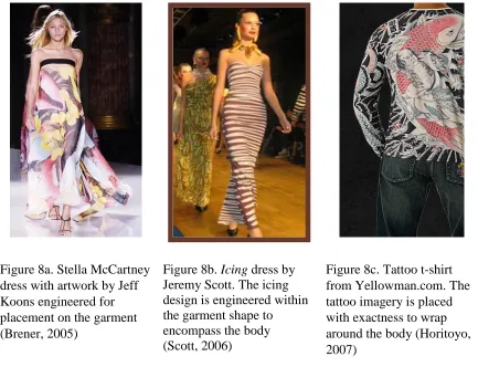
used Jeff Koons‟ artwork for her 2006 Spring/Summer collection. Koon‟s paintings are printed across five chiffon dresses by McCartney (Brener, 2005). First2Print, LLC, a textile ink jet printing bureau, allows designers to quickly produce one of a kind items for fashion shows or sale. An example, seen in Figure 8b, is a creation by designer Jeremy Scott. Scott‟s designs inspired by cartoons and fast food use large, oversize, motifs that wrap around the body. As well as allowing for engineered designs, ink jet printing is faster for one of kind items. “What really drove me to work with First2Print, LLC is the idea of doing something custom,” said Jeremy Scott, couture designer. “A lot of flatbed or even rotary printing companies just can‟t handle the time constraint and the fact that I wanted to print on fabrics like raw silk” (Digital printing dresses up couture”, 2006) Peter Mui, the owner of YellowMan, LLC also takes advantage of the engineer printing process by encompassing the body with wearable tattoos (see Figure 8c.). The tattoo imagery, collected from tattoo artists all around the globe is carefully engineered within the garment shape so that the “art falls on the body where the artist intended ” (Mui, 2006).
their garments. Knight divides design placement on the body into two distinct categories; contrived area pattern, and accidental area pattern.
Figure 8a. Stella McCartney dress with artwork by Jeff Koons engineered for placement on the garment (Brener, 2005)
Figure 8b. Icing dress by Jeremy Scott. The icing design is engineered within the garment shape to encompass the body (Scott, 2006)
Figure 8c. Tattoo t-shirt from Yellowman.com. The tattoo imagery is placed with exactness to wrap around the body (Horitoyo, 2007)
Figure 8. Examples of Engineered Print Design
designer and the fabric design is made to suit the garment, ii) textile led a process where “garments are designed in accordance with the characteristics of the surface detail of the cloth”, iii) garment as canvas, a method favoring a simple garment shape used as a canvas for highly pictorial or graphic imagery, and iv) simultaneous design, an approach where the garment shape and the surface decoration are conceived at the same time. Townsend cites Mario Fortuny as an example of a designer who utilizes a textile led approach. Fortuny‟s garments were often created in order to highlight his exquisitely printed cloths. Sonia Delauney is given as an example of a simultaneous designer. Townsend includes a quote by Delauney regarding her method of working. Delauney states that “the cut of the dress is conceived by its creator simultaneously with its decoration. Then the cut and the decoration are both printed on the same fabric” (Townsend, 2001).
2.2. Int egral Sweat er Kni tting
The evolution of the technologies for sweater manufacturing, toward integral knitting, is supportive of engineered designing. Integral knitting is one the four primary methods of sweater construction, the other three are cut and sew, garment knitted lengths, and fully fashioned. The term integrally knitted garment refers to apparel items that have typical cut and sew operations that are knitted on the machine. These operations include addition of button holes, collars, and pockets and attachment of sleeve to the garment body. Cut and sew, garment knitted blanks, and fully fashioned differ from integral knitting in that they require seaming to complete production. However, fully fashioned knitting is closer in technology to integral knitting because, unlike cut and sew and garment knitted lengths, all shaping occurs during fabric formation. Complete-garment knitting, also called knit-and-wear or WholeGarment® knitting (a registered trademark of Shima Seiki Mfg., Ltd.) is an extension of the technology of integral knitting. With complete garment knitting, no further seaming or making up processes are required upon leaving the knitting machine. Integral knitting developed from the sweater industry but now is being applied to other knitted products.
2.2.1. Market Overview
etc. All of knitted apparel, regardless of market segment, has commonalities of processes and technologies with sweater manufacturing. A distinguishing factor between sweaters and other knitted products is the gauge or coarseness of the knit. OTEXA, the Office of Textiles and Apparel within the U.S. Department of Commerce‟s International Trade Administration, defines a sweater as a knitted outerwear garment intended to cover the upper part of the body having nine or fewer stitches per two centimeters in the horizontal direction (OTEXA reference.2007). Spencer states that, generally, knitwear is knitted on machines with gauges of 14 or less (Spencer, 2001b). Both of these definitions may not accurately reflect the current market which includes finer gauge sweaters.
There are several notable technological advancements and social events that shaped the current sweater manufacturing market. It is difficult to determine when the sweater industry started, but depictions in paintings, references from historical documents and fragments of knitted fabric lead us to believe that knitted garments worn on the upper body were common by the 14th century. Knitting dates back thousands of years; remnants have been found from 280 B.C in Syria (Collier & Tortora, 2001) and from 250 A.D. near present day Palestine (Kadolph & Langford, 2002). A painting from the late 1300‟s depicts The Madonna hand knitting a seamless sweater, (Karasaunu, 1995) and by the 15th century hand knitting was recognized as a professional trade requiring six years of apprenticeship (Rowlands, 1985).
(Goadby, 1989; Nutting, 1989; Spencer, 2001b). In 1849 Mathew Townsend patented the self-acting needle from which the modern day latch needle is derived (Goadby, 1989). The flat bed knitting machine followed the circular knitting machine by more than fifty years. Lamb filed a patent for first flat knitting machine in 1866 (Nutting, 1989). By 1879 the first power operated knitting machine was in use, and in 1887 needle pickers were added to allow shaping of the heels and toes of hosiery (Goadby, 1989).
The technological advancements in knitting achieved during the Industrial Revolution helped to push the sweater market, and mass production of sweaters was evident in 1862 (Rowlands, 1985). Sweaters, often called jerseys, gained prominence during the late 1880s and early 1900s for sporting attire. The durability, stretch and warmth that knits provided were suited to outdoor activities. Although sweater manufacturing was an established industry by the 1900s, Nutting (1989) states that “prior to 1939 much of the effort of knitting technologists focused on the Lee tradition of attempting to achieve by machine what could be done by hand”. Nutting identified five trends that occurred during or after the mid 20th century that pushed technological advancements in the knitting industry. These five trends were i) emergence of new fibers and yarns, ii) integration within the knit industry of electronics, computers and computer aided design, iii) full fashioning capability, iv) increased machine productivity, and v) better quality control.
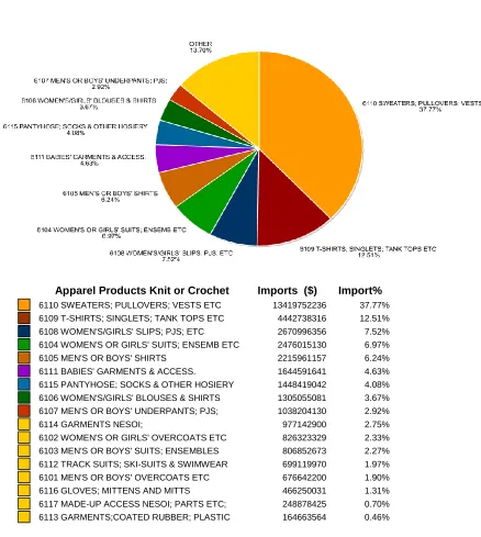
Scotland‟s twin sweater sets from the 1930‟s, the „sweater girls” of the 1940s and 1950s, the black turtleneck from the 1960s, craft revival of the 1970s, and casual work wear of the 1990s kept the sweater market strong (Black, 2002). In the United States, in a ten year period, knitted apparel fabric almost doubled; from 24% of apparel fabric in 1962 to 44% of apparel fabric in 1972. This percentage has increased to 50% of the current market. (Hatch, 1993b) The United States import market of sweaters, pullovers and vests comprise the largest category of knitted-apparel by dollar value; a $13.4 billion annual-market (see Figure 9). This data has held true since at least 1989, the earliest year that data could be gathered from OTEXA
Apparel Products Knit or Crochet Imports ($) Import% 6110 SWEATERS; PULLOVERS; VESTS ETC 13419752236 37.77% 6109 T-SHIRTS; SINGLETS; TANK TOPS ETC 4442738316 12.51%
6108 WOMEN'S/GIRLS' SLIPS; PJS; ETC 2670996356 7.52%
6104 WOMEN'S OR GIRLS' SUITS; ENSEMB ETC 2476015130 6.97%
6105 MEN'S OR BOYS' SHIRTS 2215961157 6.24%
6111 BABIES' GARMENTS & ACCESS. 1644591641 4.63%
6115 PANTYHOSE; SOCKS & OTHER HOSIERY 1448419042 4.08% 6106 WOMEN'S/GIRLS' BLOUSES & SHIRTS 1305055081 3.67% 6107 MEN'S OR BOYS' UNDERPANTS; PJS; 1038204130 2.92%
6114 GARMENTS NESOI; 977142900 2.75%
6102 WOMEN'S OR GIRLS' OVERCOATS ETC 826323329 2.33%
6103 MEN'S OR BOYS' SUITS; ENSEMBLES 806852673 2.27% 6112 TRACK SUITS; SKI-SUITS & SWIMWEAR 699119970 1.97%
6101 MEN'S OR BOYS' OVERCOATS ETC 676642200 1.90%
6116 GLOVES; MITTENS AND MITTS 466250031 1.31%
6117 MADE-UP ACCESS NESOI; PARTS ETC; 248878425 0.70%
6113 GARMENTS;COATED RUBBER; PLASTIC 164663564 0.46%
Figure 9. OTEXA Import Value of Knitted Apparel by Product Category (OTEXA reference.2007)
2.2.2. Machine Technology
In weft knitting, one knitting yarn is fed to a series of needles while in warp knitting each knitting yarn end is supplied from a warp beam, or creel to one needle (Reichman, 1972). Warp or weft knitting mechanisms and the fabrics produced on each are markedly different. Warp knitted fabric has loops that are formed in the wale direction on a set of warp yarns, while weft knitted fabric has loops that are formed in the course direction by a continuous thread. Generally, weft fabrics have more stretch than warp knitted fabrics and therefore weft knitted fabrics are used more often in apparel.Weft knitting accounts for one fourth the world‟s apparel fabric, while warp knitting makes up one sixth of the market (Spencer, 2001b).
The majority of innovation for integral knitting has occurred with weft knitting machinery, with one notable exception. At ITMA Asia 2005, Karl Mayer Textil GmbH introduced the RDPJ 6/2. This double bar raschel machine is able to form seamless garments by knitting tubes. The tubes, formed on two needle bars, can be joined at any point on the garment allowing for a seamless apparel item to be knitted. Currently the RDPJ 6/2 is available in gauges of E16 thru E24. Although a thorough literature search showed no wide spread use of warp knitting for sweater manufacturing, this warp knitting seamless machine is considerably more productive than current weft machines for integral knitting. The RDPJ 6/2 produces 12.8 meters/hour (Lo, 2006).
2.2.2.1. Weft Knitting: Straight and Flat
machines cannot match the speed of circular machines. However, the advantage of using a flat bed machine is the flexibility allowed when designing intricate structures or shaped garments.
Figure 10. Weft knitting machine classifications and shaping and production capabilities
Shaping capability and production speed, two primary considerations when manufacturing a sweater, often dictate the type of knitting machine. For example, straight bar frames are very productive for the manufacture of full fashioned sweater components; modern machines can knit up to sixteen garment parts across the width of the machine (Spencer, 2001b). Although capable of knitting integrate patterning, they are rarely used for this, rather, straight bar machines are exploited for their ability to knit garment panels that are “shaped at the selvedges by progressively increasing or decreasing the number of loops in the width of a fabric”(Brackenbury, 1992). This fully fashioned method of
Weft Knitting Machines
Circular Straight Flat
Least Most
Shaping
Production Speed
shaping referred to as, wale fashioning (see Section 2.2.3.1 Wale Fashioning) produces garment pieces that are shaped and bound around all edges. For this reason, straight bar machines are often referred to as full fashioned knitting machines.
Prior to the last decade, straight bar machines were the dominant equipment used for fully fashioned garments. Now, new technology has allowed V-bed knitting to become competitive with straight bar machines for production of shaped sweater panels. Spencer (2001) states that
Over the past thirty years, many innovations and refinements in knitting technology have gradually evolved and combined to transform the mechanically controlled V-bed machine into a computer-controlled, highly efficient and versatile knitting machine, not only for cut and sew knitwear but also for integrally-shaped panels and whole garments. In this process of evolution it has rendered the flat bed links-links superfluous, blunted the productive challenge of the circular garment-lengths machines, surpassed the straight bar frame in shaping potential both in types of shapes and knitted structures, and has extended its own gauge range capabilities.
taken in or out of action, allowing for more complex structures and shaping possibilities. An increase in the complexity of structure and shaping (enabled by electronic control) require that knitting machines have larger memory and processing capacity.
2.2.2.2. Weft Knitting: Circular Strip and Bodysize
Circular machines for sweater manufacturing are generally employed because of their high production rate. These machines are classified by their type of needle bed. For instance, a circular machine can have a single cylinder, a cylinder and dial, or double cylinders. Single cylinder machines have one set of needles while both cylinder and dial and double cylinder have two opposed needle beds. Single cylinder machines are only capable of knitting continuous yard goods, while cylinder and dial and double cylinder can knit garment knitted lengths. While circular yard goods machines are still in use, garment-length circular machines are preferred for sweater manufacturing.
are often called “seamless” because of the lack of side seams. They do, however, need to be finished and shaped around openings such as necks and armholes. Sleeves and collars can be attached by sewing methods such as linking, overlocking or cup seaming. See Section 2.2.4 Construction Methods.
2.2.3. Shaping Methods
2.2.3.1. Wale Fashioning
In wale fashioning, also called Needle to point to needle loop transfer, transfer of loops happens within the same bed. Wale fashioning can be achieved on straight bar machines or a V-bed machine using stitch transfer (Hewitt & Smith, 1981; Spencer, 2001b). A fashioning point is a mechanical, knitting machine-element that extracts and holds a selvedge loop, traverses the loop across the needle bed, and then transfers the loop onto a new needle (Hewitt & Smith, 1981). This method of shaping produces a firm, well defined selvedge edge.
Figure 11a. Stitch Shaping with five structures (Spencer 2001b)
Figure 11b. Stitch shaping with combination of 1 x 1 rib with 2 x 2 rib(Shima Seiki Mfg., Ltd. Japan 2007b)
Figure 11. Stitch shaping examples
1 x 1 Rib
2.2.3.2. Needle Selection Shaping
Needle selection shaping can occur by i) transferring rib loops by racking the needle beds, ii) pressing off loops, or iii) holding loops (Spencer, 2001b). In this method of shaping, referred to as needle to needle loop transfer, narrowing and widening is achieved by racking (moving one needle bed in relation to another) and transferring loops from the front bed to the back bed and then back again. Needle to needle loop transfer requires that needles be free to accept loops. This requires more usage of the needle bed width and slows productivity. V-bed machine manufacturers have addressed this problem by outfitting machines with four beds or placing an extra set of offset needles. Compound needles are often used as they require less space.
Individual selection of selvedge needles is the simplest method of widening and narrowing during knitting. For widening, additional selvedge needles are introduced at the fabric‟s edge in stepped increments to gradually increase the knitted width. When narrowing, needles are simply pressed off. Although the widening method is very good, narrowing by pressing off tends to cause loops to ladder and run if the takedown tension is not reduced simultaneously with needle reduction (Hewitt, Smith 1981). This has led to a number of technological advances in take down mechanisms aimed at better control of takedown tension.
Shaped garments have varying widths which require an adjustment of tension when needles are taken in or out of action or when loops are being transferred. Improved takedown mechanisms include the presser foot, takedown comb, and the sinker. Developments of these takedown devices were all aimed at improving capability of varying takedown tensions (Guy, 2001).
A patent for a presser foot was filed in 1867 by Thomas Crane, and research using the presser foot for shaping garment panels was conducted by Courtlaulds and Dubied in the 1970s (Betts & Robinson, 1979; Jeanneret, 1982). Courtlaulds also licensed this technology to machine builders Shima Seiki Mfg., Ltd. and Bentley-Cotton (Spencer, 2001b). Jeanneret (1982) of Dubied explains the presser foot mechanism and movement in the following statement:
The presser foot mechanism is securely fixed to the carriage of the machine, and moves across the machine with the carriage. The presser feet precede the needles which are rising. The wire of the presser foot slides just underneath the crossing or intersection of the opposing needles of both needlebeds and presses against the stitches laced against the needle beds. The consequence of this is that the takedown-roller becomes unnecessary.
needled beds to grab the first row of loops. Loop controlling sinkers were used by Shima Seiki Mfg., Ltd. on their glove knitting machines (B. Hunter, 2004a). Sinkers apply pressure to formed loops thus reducing the amount of tension needed by the takedown comb or roller. This pressure is applied at each individual needle and so varying tension can be obtained across the width of the shaped garment piece (Guy, 2001).
Holding loops is a technique where “the length of the courses being knitted is diminished or extended successively. No loops are lost by casting off or pressing off (dropping); all loops are stored (held) to knit at a later stage” (Brackenbury, 1992). Common names for these techniques include flechage, short row knitting or gore technique. This shaping technique requires that the carriage traverse be able to be varied, traveling shorter or longer distances when needed.
2.2.3.3. Reciprocal Shaping
2.2.4. Construction Processes
As depicted in Figure 12a-b, the main methods of sweater construction are; i) fully cut and sew, ii) garment knitted lengths, iii) full fashioned knitting, iv) integral knitting and v) hand knitting (Brackenbury, 1992). Construction methods are differentiated from each other by the amount of shaping that happens during or after fabric formation. For instance, in cut and sew construction all shaping occurs after the fabric leaves the knitting machine. Garment knitted lengths combine some machine shaping and some cut and sew shaping. Fabric is knitted to a length that corresponds to the size of the sweater. The knitted, rectangular, panels have one edge, typically the hem, which has a rib trim, all other sides are cut. Fully-fashioned construction and integral knitting differ from both fully cut and sew and garment knitted lengths in that the majority of the shaping is executed on the knitting machine rather than by pattern cutting.
Figure 12a. Fully cut and sew Figure 12b. Garment knitted lengths
Figure 12c. Fully-fashioned Figure 12d. Integral knitting Figure 12. Primary sweater construction methods (Brackenbury, 1992)
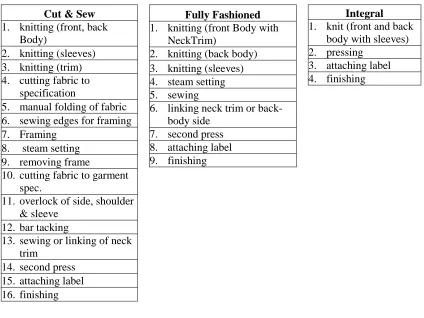
technology. The question remains whether sweater manufacturing will follow the same path. There have been a number of technological developments by knitting machine builders that would lead one to believe that integral knitting will be a key technology for sweater production. A progression toward integral knitting eliminates many steps in sweater assembly (see Table 6).
Table 6. Comparison of Production Steps for Sweater Construction (Brackenbury, 1992)
Cut & Sew
1. knitting (front, back Body)
2. knitting (sleeves) 3. knitting (trim) 4. cutting fabric to
specification
5. manual folding of fabric 6. sewing edges for framing 7. Framing
8. steam setting 9. removing frame
10. cutting fabric to garment spec.
11. overlock of side, shoulder & sleeve
12. bar tacking
13. sewing or linking of neck trim
14. second press 15. attaching label 16. finishing
Fully Fashioned
1. knitting (front Body with NeckTrim)
2. knitting (back body) 3. knitting (sleeves) 4. steam setting 5. sewing
6. linking neck trim or back-body side
7. second press 8. attaching label 9. finishing
Integral
1. knit (front and back body with sleeves) 2. pressing
2.2.4.1. Cut and Sew
Cut and sew processes tend to be faster, and less expensive than other sweater construction processes. For the cut and sew method, fabric can be knitted in continuous yardage or knitted in garment lengths on a flat bed or a circular knitting machine. Both yardage and garment lengths can be knitted in an open width or circular tube. Cutting can be done by hand by a pattern cutter or by an automatic cutting machine. In a cut and sewn sweater a pattern cutter, (sometimes referred to as the makeup person) or apparel designer, can generate the shape of the sweater (Eckert, 2001). Cut and sewn garments usually use the horizontal direction of the fabric for the circumference of the body. While knitted fabric is extensible in the horizontal and vertical direction, vertical extensibility is generally only half as great as horizontal extensibility. Vertical elongation is equal to one half the loop lengths while horizontal extension is equal to almost the entire loop length. This allows the greatest stretch to be to be used around the garment‟s girth while ensuring that the garment length has the least potential for sagging and distorting (Brackenbury, 1992).
marking, cutting, sewing, and finishing processes can be challenging for knits because at each of these stages the fabric has the potential to distort (Brackenbury, 1992).
Knitted garment lengths are knitted in a predetermined length of fabric that corresponds to the finished garment length. Sweaters that are knitted as garment lengths may also be called stitch-shaped cut, because the change in structure from the waist band to the body imparts some shape to the garment (Brackenbury, 1992). Typically, garment knitted lengths have a ribbed cuff knitted in to the bottom of the fabric so that no finishing is required at the sweater‟s bottom edge. These pre-determined body lengths can be knitted as separate articles or knitted as a series of garment blanks strung together (Spencer, 2001). If knitted as a string, then a removable separator-thread is knit between the last course of the previous panel and the first course of the new panel‟s welt. See Figure 13.
Figure 13. Diagram of separator thread insertion for garment knitted length (Raz, 1993)
1. Last course of previous panel.
2. The draw thread.
3. Threading of new panel and welt.
4. The rib border.
5. The transition from 2x2 rib to next panel.
2.2.4.2. Fully Fashioned
Shaping on the knitting machine by narrowing or widening is called fashioning, and garments shaped by this manner are referred to as fully fashioned. Fully fashioned sweaters are defined as “garments constructed from pieces of weft knitted fabric with perfect selvedges. The shapes of the pieces are generated by movement of loops at the edges to diminish or enlarge the width of the fabric (Brackenbury, 1992).” Fully fashioned or shaped sweaters are typically produced on either straight bar or V-beds. The shaping is achieved by wale fashioning or needle selection shaping.
twenty are distributed among the needed 28. Therefore there are 20 fashionings at eight course intervals and eight fashioning at four course intervals.
Figure 14. Calculation of a fashioning frequency. (Raz 1991 )
R.W. Mill (1965) researched fashioning angle and devised calculations to determine fashioning frequencies. However, these calculations were based on fashioning with a straight bar frame and according to Guy (2001) Mill‟s calculations do not reflect current shaping possibilities using fully electronic V-beds. Guy states that current designers use a combination of fashioning calculations and trial and error.
2.2.4.3. Assembly
The majority of sweater construction methods, with the exception of integral knitted garments require some type of seaming or joining method. “Seams are used to assemble fabric panels, to create the structure and detail of a garment (Brown & Rice, 1998b).” Seam strength is a major consideration for good quality seams for woven garments. Seams need to be as strong as the fabrics they are joining (Brown & Rice, 1998). However, for knitted garments, along with strength, a primary concern for seams is extensibility (Brackenbury, 1992).
2.2.4.3.1. Overlock
The overlock stitch is a highly extensible stitch that joins, binds (Brackenbury, 1992) and trims knitted sweater components. The overlock also called overedge, serge, overcast or Merrow falls under class 500 in the ASTM 6193, Standards Relating to Stitches and Seams (Glock & Kunz, 2005). Overlocking is the predominate method of seaming for sweaters that are fully cut and sewn because it can cover the raw edge of the sweater. The most widely used overlock seam, type 504, has three threads comprising one needle thread and two looper threads. Quality factors of the overlock stitch include; i) stitches per unit length, ii) the bite (the distance from the edge of a fabric that the needle thread penetrates), iii) run in ratio of the three seams and, iv) the balance in run between the looper threads (Brackenbury, 1992).