EMB Position Control Using a PI Gain
Scheduling Method
Donghoon Ban
1, Sungho Jin
2, Jaeseung Hong
3Senior Research Engineer, Convergence Research Center for Future Automotive Technology, DGIST, Daegu, Korea1 Principal Research Engineer, Convergence Research Center for Future Automotive Technology, DGIST, Daegu, Korea2
Research Engineer, Convergence Research Center for Future Automotive Technology, DGIST, Daegu, Korea3
ABSTRACT:A brake system is a nonlinear system which applies different compressive force depending on the position of the brake pad. The EMB(electric mechanical brake) used in passenger vehicles cannot detect the compressive force without a sensor. Therefore, it has different operating times at the same distance because the brake caliper applies different force depending on the position of the brake pad. A position controller for the EMB system was developed to control the operating time robustly at the same distance. A vector control method was used to operate the motor. The result of the position controller was used as the Q axis reference for the vector control method. The PI gain of the position was defined differently to meet the same operating time of the motor on each sector. In addition, the interval value between each position was calculated using an interpolation method. A PI gain of the position controller was tuned using the MATLAB tool, and the reliability of the position controller was verified through a simulation in the MATLAB. The verified PI controller was installed in an EMB system. The operating times were measured on each sector, showing that they were nearly identical. The proposed PI scheduling method was confirmed to have robust characteristics in a nonlinear EMB system with different amounts of compressive force depending on the position of the brake pad.
KEYWORDS:EMB, Vector control, PI control, Gain scheduling, Motor-control, Interpolation
I. INTRODUCTION
II. RELATED WORK
There are many PI controllers in the industry and many papers about the PI gain control are published. A PI controller which has a unique PI gain is very difficult to meet a performance of system. There are two main solutions to solve the problem. The first group is studying methods using the FUZZY [1]. Whereas the second group is studying solutions using the gain scheduling method in [2] and in [3]. A speed controller using a gain scheduling is shown in [4] and in [5]. Additionally, a vector control for operating a motor is being studied in [5] and in [6].
III.EMB SYSTEM
1. Interpolation
The forcebetween ono point and another point is calculated by linear interpolation. An interpolation method uses a straight line equation which connects the two points. The straight line function is estimated as an approximate function. When a simple function is used to estimate data points from the actual data, interpolation errors are usually present; however, depending on the problem domain and the interpolation method used, the gain in simplicity may be of greater value than the resultant loss in accuracy. The function f 𝑥 is defined in a closed range[𝑥1, 𝑥2]. Additionally, function
values are known on n points (𝑥1, 𝑥2, 𝑥3,···, 𝑥𝑛) on this range. The known equation of a straight line passing any two points can be used. The value g 𝑥 is the function value between any point 𝑥1and 𝑥2, as expressed by equation(1).
𝑔 𝑥 = 𝑓 𝑥1 +
𝑓 𝑥2 − 𝑓 𝑥1
𝑥2 − 𝑥1 (𝑥 − 𝑥1) (1)
2. EMB position controller design
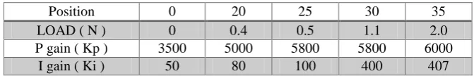
A position controller was designed to operate the EMB using a PI controller. [6-8].Fig. 1 shows a block diagram of the EMB position controller. Table. 1 defines the PI gain depending on the position. The vector controller determines the PWM value using the phase current from the motor. The PWM module operates the motor. This is the motor control sequence. The input reference of the vector controller is the error between the result of the position controller and the phase current from the motor.
Fig. 1 Block diagram of the position PI controller
Table.1 PI gain depending on the position
Position 0 20 25 30 35
LOAD ( N ) 0 0.4 0.5 1.1 2.0
P gain ( Kp ) 3500 5000 5800 5800 6000
I gain ( Ki ) 50 80 100 400 407
Each P and I gain values is designed differently on each sector to meet the same operating time at the same distance due to the different compressive force depending on the position between the pad and the disk. The PI controller calculates the error between the actual value and the reference value. The PI gain cam adjust the response time and the setting time. The PI control equation is named after its two correcting terms, whose sum constitutes the manipulated
POSITION PI
CONTROLLER CONTROLLERVECTOR MODULATIONPWM MOTOR
POSITION
Q axis current reference
phase current MOTOR CONTROL
EMB CONTROL
+-variable. The proportional and integral are summed to calculate the output of the PI controller. Equation (2) is the final form of the PI equation.
u 𝑡 = 𝐾𝑝𝑒 𝑡 + 𝐾𝑖 𝑒 𝜏 𝑡
0 𝑑𝜏 (2) where the following nomenclature applies:
𝐾𝑝 : Proportional gain
𝐾𝑖 : Integral gain
𝑒 𝑡 : Error = reference value - real value
t : time
τ : variable of integration
𝑢 𝑡 : controller output
IV.EMBSYSTEM
1. EMB position controller design in MATLAB
Fig. 2 shows the EMB system designed using the MATLAB tool. The vector control method is operated in the motor controller. The load of the motor is given by the EMB model. The position controller is designed using the PI controller, and the result is used as the reference of the Q-axis current. The function of each of the labelled blocks is as follows:
1) Reference position: The required position is set using a constant block.
2) PI position block: The error signal is obtained by subtracting the reference position from the real position. For the PI control, MATLAB’s library is used.
3) Motor block: The electrical and mechanical equation of a PMSM.
4) Vector control block: The inputs to this subsystem are the required values of the direct axis(Id), the quadrature axis(Iq) current and the real-time value of theta which is fed back. The direct axis component of the stator current produces useless compression force. Ideally, we would prefer if the direct axis component is 0. Hence, we set the required value of Id to a constant value of 0.
5) Sinusoidal PWM block: This subsystem generates the six PWM waveforms for the FET circuit.
6) EMB model: The load is modelled as an EMB whose value is denoted in force (N). This load force is used in the main motor subsystem to compute other quantities.
7) FET circuit: A three-arm, 6-FETinverter circuit is implemented. The gating pulses (PWM) are provided by the sinusoidal PWM control subsystem.
8) Scope blocks are used to observe the various waveforms in real time.
9) The speed computed by the PMSM model block is in radians/sec. However, for the sake of user convenience, it is converted to RPM.
Fig. 2 Motor system model for EMB in MATLAB
2. Configuration of an actual controller and an actual inverter
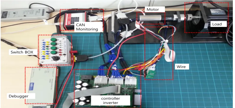
An actual controller and an actual inverter in a motor were developed to operate the EMB system. Fig. 3 shows the controller and the inverter for the EMB. The EMB system consists of a control board, an inverter board, CAN monitoring equipment, wiring, a switch-box, the motor, and load equipment. Three FETs were connected in parallel to supply sufficient power to allow the inverter to supply the current required by the motor. The control board and the inverter board can operate the motor. The CAN monitoring equipment can monitor the variables of the software in the motor control. The control board was controlled by the switch box, which has 4 switches and 1 potential meter. The load equipment applies the load. The motor is identical to that used in the EMB. The wire has the hall signal and the power of the motor.
Fig. 3 Configuration of the EMB system
Inverter model
Motor model
Monitoring scope PWM generation
Vector control
EMB model
controller inverter
Wire Motor
Load CAN
Monitoring
Switch BOX
V. EXPERIMENTAL RESULTS
1. Simulation Result
An EMB controller has the PI gain differently depending on the load. It designed using the EMB model and that was simulated with the time between each sector measured. It was confirmed that there were no differences in time between the initial position and the final position. The initial position has almost no load. The final position has a load close to the maximum load. Table. 2 shows the result of the simulation. When the motor moves a distance equal to 5 cycles of the motor, the operating times are nearly identical. The EMB controller operates every 10ms; hence, variation of 20ms is minor.
Table. 2 Simulation results of the EMB MATLAB model
Load(N) 0 0.4 0.5 1.1 2.0
Time(ms) 160 160 170 170 180
2. Actual load result
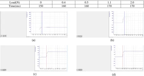
After creating the EMB system, the operating time of each sector was measured. Table. 3 shows the result under an actual load, and Fig. 4 shows the response time at each load. The sector duration is 5cycles of the motor; this is displayed as 500. The position controller was operated every 10ms. The result shows that time deviation is less than 20ms, therefore showing an accurate response time. The EMB controller was designed using the PI gain scheduling method proposed in this paper, and it operated precisely as predicted. It was also confirmed that the times is nearly identical regardless of the load.
Table. 3 Actual load result of the EMB system
Load(N) 0 0.4 0.5 1.1 2.0
Time(ms) 150 160 160 170 170
Fig. 4 Test result depending on the load: (a) The response time without a load (b) The response time with a 0.5N load (c) The response time with a 1.1N load (d) The response time with a 2.0N load
VI.CONCLUSION
A brake system is a nonlinear system which applies different amounts of force depending on the brake pad position. An EMB system cannot control the force directly because it cannot detect the force; thus, it has different operating
(a) (b)
times for each position. A position controller for an EMB system was designed to operate robustly in any position. A three phase BLAC motor was controlled using a vector control method. The output of the position controller was used as the current reference of the Q axis. The PI gain was designed differently to meet the same ope rating time for each sector, and the reliability of the PI controller was verified in a MATLAB simulation. The designed PI controller was installed into an EMB system and the operating time was measured depending on the load. The operat ing times were nearly identical. So the proposed PI position controller with the scheduling method has been robust and accurate.
ACKNOWLEDGMENTS
This work was supported by the DGIST R&D Program of the Ministry of Science, ICT and Technology of Korea(15-RS-03).
REFERENCES
[1] M. Cam, “A fuzzy gain scheduling PI controller application for an interconnected electrical power system”, International Journal of Electrical Power Energy Systems, Vol. 73, No. 3, pp. 267-274, 2004
[2] M. A. Ahmed, H. Bassiuny and M. Bakr, “Design and Implementation of Gains Scheduled PI Control System for Shape Memory Alloy Actuator”, International Journal of Modeling and Optimization, Vol. 3, No. 2, pp. 120-124, 2013
[3] J. Gao and H. M. Budman, “Design of robust gain-scheduled PI controllers for nonlinear processes”, Journal of Process Control, Vol. 15, No.7, pp. 807-817, 2005
[4] D. H. Ban, J. H. Park and Y. D. Lim, “Speed Control of a Permanent Magnet Synchronous Motor for Steering System Using Fuzzy Algorithm”,Journal of Institute of Control, Robotics and Systems, Vol. 18, No. 6, pp. 526-531, 2012.
[5] Y. S. Choi, D. Y. Yu, H. H. Choi and J. W. Jung, “A Study on the Gain Scheduling Speed Controller of Permanent Magnet Synchronous Generators for MW-Class Direct-Driven Wind Turbine Systems”, Journal of Korean Institute of Illuminating and Electrical Installation Engineers, Vol. 25, No. 8,pp. 48-59, 2011
[6] D. H. Ban, T. Y. Lee and S. H. Jin, “Design and Implementation of an EPB Diagnostic”, Journal of Automation and Control Engineering, Vol. 3, No. 4, pp. 311-315, 2015
BIOGRAPHY
Donghoon Ban received a B.S. degree in electrical engineering from Donga University, Busan, Korea in 1999, M.S. Degree in electrical engineering from Busan University, Busan, Korea in 2006, and a Ph. D. in electrical engineering from Donga University, Busan, Korea in 2013.He is a senior research engineer at Daegu Gyeongbuk Institute of Science & Technology (DGIST). He is developing components of vehicles such as the Body Control Module and Electronic Parking Brake based on AUTOSAR. His research interests are Fuzzy control, BLAC motor control, inverters, and AUTOSAR.
Sungho Jinreceived a B.S. and M.S. degree in electrical engineering from Kyungpook National University, Daegu, Korea, in 1989 and 1991, respectively. He is a Principal Research Engineer with the Daegu Gyeongbuk Institute of Science and Technology, Daegu, Korea. His research interests include automotive embedded systems, modeling and simulation for electric vehicles, and motorapplication systems.