Improved Active Power Filter Performance for
Renewable Power Generation System with Buck
Boost Converter using Predictive Control
Algorithm
M.THEJASWI1, V.RAMA KRISHNA2, M.SREENIVASULU3
1PG Student [EPS], Dept. of EEE, ASIT, Gudur, SPSR Nellore (D), Andhra Pradesh, India
2Assistant Professor, Dept. of EEE, ASIT, Gudur, SPSR Nellore (D), Andhra Pradesh, India
3
Assistant Professor, Dept. of EEE, ASIT, Gudur, SPSR Nellore (D), Andhra Pradesh, India
ABSTRACT: The active power filter for non- linear load along with its control scheme and also implemented with a four-leg voltage source inverter using a predictive control scheme is presented. The active power filter is used to compensate the reactive power, reduce current harmonics and voltage distortions in the power system. The active power filter provide better performances in the high voltage non linear load compensation. Renewable energy with Buck-boost converter is used to balance the dc link voltage. The predictive controller use to improve the performance of the active power filter, especially during transient operating conditions, because it can quickly follow the current– reference signal while maintaining a constant dc voltage.
The compensation performance of the proposed active power filter and associated control scheme under steady state and transient operating conditions is demonstrated through simulation and experimental result.
KEYWORDS: Active power filter, current control, four-leg converters, predictive control.
I. INTRODUCTION
The wide spread increase of non-linear loads now-a-days significant amounts of harmonic currents are being injected into power systems Harmonic currents flow through the power system impedance, causing voltage distortion at armonic currents frequencies. The distorted voltage waveform causes harmonic currents to be drawn by other loads connected at the point of common coupling (PCC).The existence of current and voltage harmonics in power systems increases losses in the lines, decreases the power factor and can cause timing errors in sensitive electronics equipments[1],[6].The continuous demand in power network has caused the system to be heavily loaded leading to voltage instability. Under heavy loaded conditions there may be insufficient reactive power causing the voltages to drop. This drop may lead to drops in voltage at various buses. The result would be the occurrence of voltage collapse which leads to total block out of the whole system.
The active power filter is connected parallel to the point of common coupling is used to compensate the reactive power[8], reduce harmonics in the source current and also injects the active power from the renewable energy source into the grid through VSI[2],[4]. It exhibits faster control of reactive power to provide voltage stabilization, flicker suppression, and other types of system control. The active power filter provide better performances in the high voltage non linear load compensation. The APF consists of 4-leg VSI, 3-legs are needed to compensate the 3-phase currents and 1-leg compensates the neutral current[2],[3],[5].The fourth leg increases switching states from 8(23) to 16(24), improving control flexibility and output voltage quality, and suitable for current unbalance compensation[4].The Active power filter is modeled to achieve the power factor correction and voltage regulation along with neutral current compensation, harmonic elimination and load balancing with linear loads and non-linear loads.A predictive control algorithm is employed for obtaining the reactive power compensation and voltage regulation for two level four leg VSI based active power filter.
II.TWO-LEVEL FOUR-LEG PWM-VSI TOPOLOGY:
It consists of various types of power generation units and different types of loads. Renewable sources, such as wind and sunlight, are typically used to generate electricity for residential users and small industries. Both types of power generation use ac/ac and dc/ac static PWM converters for voltage conversion and battery banks for long term energy storage. These converters perform maximum power point tracking to extract the maximum energy possible from wind and sun. The electrical energy consumption behavior is random and unpredictable, and therefore, it may be single- or three-phase, balanced or unbalanced, and linear or nonlinear. An active power filter is connected in parallel at the point of common coupling to compensate current harmonics, current unbalance, and reactive power. It is composed by an electrolytic capacitor, a four-leg PWM converter, and a first-order output ripple filter, as shown in Figure. This circuit considers the power system equivalent impedance Zs , the converter output ripple filter impedance Zf , and
the load impedance Zf . The four-leg PWM converter topology is shown in Figure. This converter topology is similar
to the conventional three-phase converter with the fourth leg connected to the neutral bus of the system. The fourth leg increases switching states from 8 to 16, improving control flexibility and output voltage quality, and is suitable for current unbalanced compensation. A dq-based current reference generator scheme is used to obtain the active power filter current reference signals. This scheme presents a fast and accurate signal tracking capability. This characteristic avoids voltage fluctuations that deteriorate the current reference signal affecting compensation performance. The current reference signals are obtained from the corresponding load currents as shown in Figure. This module calculates the reference signal currents required by the converter to compensate reactive power, current harmonic, and current imbalance.
Fig.2. Two-level four-leg PWM-VSI topology
Fig. 1 shows the power circuit of a 4-leg shunt APF connected in parallel with the 1-phase and 3-phase loads as an unbalanced and non-linear load on 3-phase 4-wire electrical distribution system. The middle point of each branch is connected to the power system through a filter inductor. The voltage in any leg x of the converter, measured from the neutral point (n), can be expressed in terms of switching states, as follows:
Vxn= Sx− Sn Vdc, x= u, v, w, n. (1)
V0 =Vxn – Reqi0 – Leq 𝑑𝑖0
𝑑𝑡 (2)
where Req and Leq are the 4L-VSI output parameters expressed as Thevenin impedances at the converter output
terminals Zeq .Therefore, the Thevenins equivalent impedance is determined by a series connection of the ripple filter Zf
impedance and a parallel arrangement between the system equivalent impedance Zs and the load impedance ZL
Zeq= ZsZL
Zs+ ZL
+Zf≈ Zs+ Zf (3)
For this model, it is assumed that ZL >> Zs , that the resistive part of the system’s equivalent impedance is neglected,
and that the series reactance is in the range of 3–7% p.u., which is an acceptable approximation of the real system. Finally, in( 2) Req = Rfand Leq = Ls+ Lf .
III . THREE-PHASE EQUIVALENT CIRCUIT OF THE PROPOSED SHUNT ACTIVE POWER FILTER WITH BUCK-BOOST CONVERTER
Fig.3.shows the solar power generation with buck-boost converter[19]. The power generation use dc/ac static PWM converter for voltage conversion and battery banks for long term energy storage. Renewable energy with Buck-boost converter is used to balance the dc link voltage[19],[20]. The problems on The distribution network due to non-linear loads that contributes for the current harmonics and low system voltage. The voltage regulation and the power quality in the distribution feeder is improved by installing a shunt compensator.
Fig. 3. Three-phase equivalent circuit of the proposed shunt active power filter with buck-boost converter
The harmonic components in current and voltage waveforms are the most important among these. Conventionally passive filters have been used to eliminate line current controlled voltage source inverters can be utilized with appropriate control strategy to perform active filter functionality. Renewable energy sources are available abundantly in nature. Solar energy freely available in nature and a clean fuel can be harnessed to produce electricity[8]. Sunlight is available only during day time, hence it is necessary to store the generated electric power in batteries for utilization when required. Conventional process includes inversion, step up, transmission, step-down, rectification and filtration for the utilization of power[12]. These steps can be eliminated by use of buck boost converter.
IV. BUCK-BOOST CONVERTER
Fig.4. Buck-boost converter
Parameters:
The following four parameters are needed to calculate the power stage: 1. Input voltage range: Vinmin and Vinmax
2. Nominal output voltage: Vout 3. Maximum output current: Iout
4. Integrated circuit used to build the buck-boost converter. This is necessary because some parameters for the calculations must be derived from the data sheet.
The duty cycle is always positive and less than 1. the characteristics of the buck–boost converter are mainly:
polarity of the output voltage is opposite to that of the input.
The output voltage can vary continuously from 0 to (for an ideal converter). The output voltage ranges for a buck and a boost converter are respectively 0 to and to .
V.DIGITAL PREDICTIVE CURRENT CONTROL
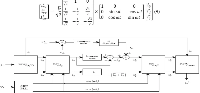
The predictive control algorithm is used to predict the future behavior of the variables to be controlled[10],[11]. The dq-based scheme operates in a rotating reference frame; therefore, the measured currents must be multiplied by the sin(wt) and cos(wt) signals. By using dq-transformation, the current component is synchronized with the corresponding phase-to-neutral system voltage, and the q current component is phase-shifted by 90◦. The sin(wt) and cos(wt) synchronized reference signals are obtained from a synchronous reference frame (SRF) PLL[13]. The SRF-PLL generates a pure sinusoidal waveform even when the system voltage is severely distorted[8],[9]. Tracking errors are eliminated, since SRF-PLLs are designed to avoid phase voltage unbalancing, harmonics (i.e., less than 5% and 3% in fifth and seventh, respectively), and offset caused by the nonlinear load conditions and measurement errors[11],[21]. A low-pass filter (LFP) extracts the dc component of the phase currents id to generate the harmonic reference components
−𝑖𝑑~. The reactive reference components of the phase-currents are obtained by phase-shifting the corresponding ac and
dc components of 𝑖𝑞by 180◦. In order to keep the dc-voltage constant, the amplitude of the converter reference current
must be modified by adding an active power reference signal 𝑖𝑒with the d-component[7]. The resulting signals 𝑖𝑑∗and
𝑖𝑞∗ are transformed back to a three-phase system. The predictive controller use to improve the performance of the
active power filter, especially during transient operating conditions, because it can quickly follow the current - reference signal while maintaining a constant dc voltage
Fig. 5. Proposed predictive digital current control block diagram
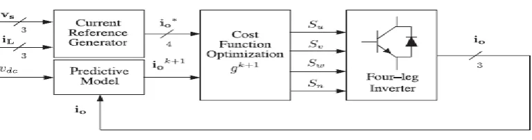
[10], [22]–[27]. The main characteristic of predictive control is the use of the system model to predict the future behavior of the variables to be controlled. The controller uses this information to select the optimum switching state that will be applied to the power converter, according to predefined optimization criteria. The predictive control algorithm is easy to implement and to understand, and it can be implemented with three main blocks, as shown in Fig. 5.
1) Current Reference Generator: This unit is designed to generate the required current reference that is used to compensate the undesirable load current components. In this case, the system voltages, the load currents, and the dc-voltage converter are measured, while the neutral output current and neutral load current are generated directly from these signals (IV).
2) Prediction Model: The converter model is used to predict the output converter current. Since the controller operates in discrete time, both the controller and the system model must be represented in a discrete time domain [22]. The discrete time model consists of a recursive matrix equation that represents this prediction system. This means that for a given sampling time Ts knowing the converter switching states and control variables at instant kTs , it is possible to predict the next states at any instant [k + 1]Ts .Due to the first-order nature of the state equations that describe the model in (1)–(2), a sufficiently accurate first-order approximation of the derivative is considered in this paper
𝑑𝑥 𝑑𝑡 ≈
𝑥 𝑘+1 −𝑥 𝑘
𝑇𝑠 (4)
The 16 possible output current predicted values can be obtained from (2) and (4) as
𝑖𝑜 𝑘 + 1 = 𝑇𝑠
𝐿𝑒𝑞 𝑉𝑥𝑛 𝑘 − 𝑉𝑜 𝑘 + 1 −
𝑅𝑒𝑞 𝑇𝑎
𝐿𝑒𝑞 𝑖𝑜 𝑘 (5)
As shown in (5), in order to predict the output current i0 at the instant (k + 1), the input voltage value 𝑉𝑜and the
converter output voltage , are required. The algorithm calculates all 16 values associated with the possible combinations that the state variables can achieve.
3) Cost Function Optimization: In order to select the optimal switching state that must be applied to the power converter, the 16 predicted values obtained for 𝑖𝑜 [k + 1] are compared with the reference using a cost function g, as follows:
g[k+1]=(i*ou[k+1]-iou[k+1]) 2
+(i*ov[k+1]-iov[k+1]) 2
+(i*ow[k+1]-iow[k+1]) 2
+(i*on[k+1]-ion[k+1]) 2
(6)
The output current (i0) is equal to the reference (i*o) when g = 0. Therefore, the optimization goal of the cost function is to achieve a g value close to zero. The voltage vector 𝑉𝑥𝑁 that minimizes the cost function is chosen and then applied at the next sampling state. During each sampling state, the switching state that generates the minimum value of g is selected from the 16 possible function values. The algorithm selects the switching state that produces this minimal value and applies it to the converter during the k + 1 state.
VI. CURRENT REFERENCE GENERATION
required by the converter to compensate reactive power, current harmonic, and current imbalance. The displacement power factor (sin ∅(𝐿)) and the maximum total harmonic distortion of the load (𝑇𝐻𝐷(𝐿))defines the relationships
between the apparent power required by the active power filter, with respect to the load, as shown
SAPF
S𝐿 =
sin ∅(𝐿)+𝑇𝐻𝐷(𝐿)2
1+𝑇𝐻𝐷(𝐿)2
(7)
where the value of 𝑇𝐻𝐷(𝐿) includes the maximum compensable harmonic current, defined as double the sampling
frequency fs . The frequency of the maximum current harmonic component that can be compensated is equal to one half of the converter switching frequency. The dq-based scheme operates in a rotating reference frame; therefore, the measured currents must be multiplied by the sin(wt) and cos(wt) signals. By using dq-transformation, the d current component is synchronized with the corresponding phase-to-neutral system voltage, and the q current component is phase-shifted by 90◦. The sin(wt) and cos(wt) synchronized reference signals are obtained from a synchronous reference frame (SRF) PLL [29]. The SRF-PLL generates a pure sinusoidal waveform even when the system voltage is severely distorted. Tracking errors are eliminated, since SRF-PLLs are designed to avoid phase voltage unbalancing, harmonics (i.e., less than 5% and 3% in fifth and seventh, respectively), and offset caused by the nonlinear load conditions and measurement errors [30]. Equation (8) shows the relationship between the real currents 𝑖𝐿𝑥 (t) (x = u, v,w)
and the associated dq components (𝑖𝑑and 𝑖𝑞)
𝑖𝑑
𝑖𝑞 = 2 3
sin 𝜔𝑡 cos 𝜔𝑡
− cos 𝜔𝑡 sin 𝜔𝑡
1 −1
2 −
1
2
0 3
2 − 3 2 𝑖𝐿𝑈 𝑖𝐿𝑣 𝑖𝐿𝑤 (8)
Alow-pass filter (LFP) extracts the dc component of the phase currents 𝑖𝑑to generate the harmonic reference
components −_𝑖𝑞 . The reactive reference components of the phase-currents are obtained by phase-shifting the
corresponding ac and dc components of 𝑖𝑞by 180◦. In order to keep the dc-voltage constant, the amplitude of the
converter reference current must be modified by adding an active power reference signal 𝑖𝑒 with the d-component, as
will be explained in Section IV-A. The resulting signals id and iqare transformed back to a three-phase system by
applying the inverse Park and Clark transformation, as shown in (9). The cutoff frequency of the LPF used in this paper is 20 Hz
𝑖𝑜𝑢∗
𝑖𝑜𝑣∗
𝑖𝑜𝑤∗
= 2
3 1
2 1 0
1 2 − 1 2 3 2 1 2 − 1 2 − 3 2 ×
1 0 0
0 sin 𝜔𝑡 −cos 𝜔𝑡
0 cos 𝜔𝑡 sin 𝜔𝑡
𝑖0
𝑖𝑑∗
𝑖𝑞∗
(9)
The current that flows through the neutral of the load is compensated by injecting the same instantaneous value obtained Fig. 6. Relationship between permissible unbalance load currents, the corresponding third-order harmonic content, and system current imbalance (with respect to positive sequence of the system current, is,1 ). from the phase-currents, phase-shifted by 180◦, as shown next
𝑖𝑜𝑛∗ = − 𝑖𝐿𝑢+ 𝑖𝐿𝑣+ 𝑖𝐿𝑤 (10)
One of the major advantages of the dq-based current reference generator scheme is that it allows the implementation of a linear controller in the dc-voltage control loop. However, one important disadvantage of the dq-based current reference frame algorithm used to generate the current reference is that a second order harmonic component is generated in idand iq under unbalanced operating conditions. The amplitude of this harmonic depends on the percent of
unbalanced load current (expressed as the relationship between the negative sequence current iL,2 and the positive
sequence current iL,1 ). The second-order harmonic cannot be removed from idand iq, and therefore generates a third
harmonic in the reference current when it is converted back to abc frame [31]. Fig. 6 shows the percent of system current imbalance and the percent of third harmonic system current, in function of the percent of load current imbalance. Since the load current does not have a third harmonic, the one generated by the active power filter flows to the power system.
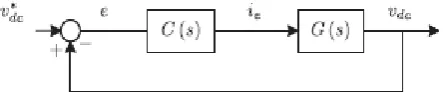
Fig. 7. DC-voltage control block diagram.
A. DC-Voltage Control
The dc-voltage converter is controlled with a traditional PI controller. This is an important issue in the evaluation, since the cost function (6) is designed using only current references, in order to avoid the use of weighting factors. Generally, these weighting factors are obtained experimentally, and they are not well defined when different operating conditions are required. Additionally, the slow dynamic response of the voltage across the electrolytic capacitor does not affect the current transient response. For this reason, the PI controller represents a simple and effective alternative for the dc-voltage control. The dc-dc-voltage remains constant (with a minimum value of √6 vs(rms) ) until the active power absorbed
by the converter decreases to a level where it is unable to compensate for its losses. The active power absorbed by the converter is controlled by adjusting the amplitude of the active power reference signal 𝑖𝑒, which is in phase with each
phase voltage. In the block diagram shown in Fig. 5, the dc-voltage vdc is measured and then compared with a constant
reference value vdc. The error (e) is processed by a PI controller, with two gains, Kpand Ti.Both gains are calculated
according to the dynamic response requirement. Fig. 7 shows that the output of the PI controller is fed to the dc-voltage transfer function Gs, which is represented by a first-order system (11)
G(s)=𝑉𝑑𝑐
𝑖𝑒 = 3 2
𝐾𝑝𝑉𝑠 2
𝐶𝑑𝑐𝑉𝑑𝑐∗ (11)
The equivalent closed-loop transfer function of the given system with a PI controller (12) is shown in (13) C(S)=𝐾𝑝 1 +
1
𝑇𝑖.𝑆 (12)
𝑉𝑑𝑐 𝑖𝑒 =
𝜔 𝑛2 𝑎 𝑠+𝑎
Since the time response of the dc-voltage control loop does not need to be fast, a damping factor ζ = 1and a natural angular speed ωn= 2π · 100 rad/s are used to obtain a critically damped response with minimal voltage oscillation. The
corresponding integral time Ti = 1/a (13) and proportional gain Kpcan be calculated as(15)
𝜁 = 3
2
𝐾𝑝𝑉𝑠 2𝑇𝑖
𝐶𝑑𝑐𝑉𝑑𝑐∗
(14)
𝜔𝑛 =
3 8
𝐾𝑝𝑉𝑠 2𝑇𝑖
𝐶𝑑𝑐𝑉𝑑𝑐∗𝑇𝑖
(15)
VII.SIMULATION RESULTS
A simulation model for the three-phase four-leg PWM converter with the parameters shown and has been developed using MATLAB- Simulink. The objective is to verify the current harmonic compensation effectiveness of the proposed control scheme under different operating conditions. A six-pulse rectifier was used as a nonlinear load. The proposed predictive control algorithm was programmed using an S-function block that allows simulation of a discrete model that can be easily implemented in a real-time interface (RTI) on the d SPACE DS1103R&D control board. The total harmonic distortion, or THD, of a signal is a measurement of the harmonic distortion present and is defined as the ratio of the sum of the powers of all harmonic components to the power of the fundamental frequency. Fig.6(d) shows the total harmonic distortion display at the output side for an uncompensated model. The load voltage and current is taken as the input. It displays the four continuous cycles of load voltage in which the distortions obtained is as 14.24% at the fundamental frequency. In uncompensated system the THD(Total harmonic distortion) is 14.2 percent. From compensated system by using the predictive control algorithm the THD is 5.07 percent.
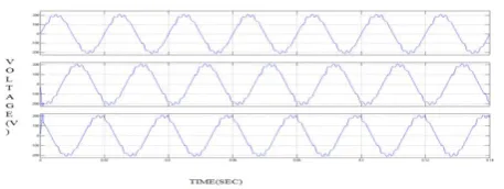
VIII. SIMULATED WAVE FORMS OF OPEN LOOP
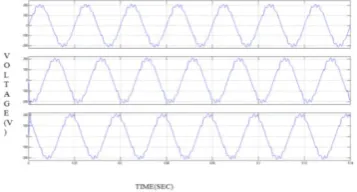
Fig. 8(a) .shows the results of three phase source voltage of open loop.
The input voltage from the open loop is 210v
Fig. 8(c) .three phase output load current of open loop and the value of the three phase load current is 20A
Fig. 8(d) .THD display of open loop
IX. SIMULATED WAVE FORMS OF CLOSED LOOP:
Fig. 9(a) .shows the results of three phase source voltage of closed loop.
Fig.9(c) .Three phase output current of closed loop.
FFT ANALYSIS OF CLOSED LOOP:
Fig.9(d).shows the total harmonic distortion display at the output side for a compensated model.
IX. CONCLUSION
The predictive control algorithm used as reactive power compensation and voltage regulation for VSC-based shunt active power filter. The proposed Predictive controller consists of the inner current loop and outer voltage loop controller. For the inner loop, the predictive control algorithm is employed to generate proper switching functions for the VSC-Based shunt active power filter and to achieve the current and voltage regulation. The simulation results shows that the proposed model can compensate the reactive power flow thereby improving the system response and decrease the THD. Therefore, the proposed predictive control strategy is adequate for VSC-based shunt active power filter.
REFERENCES
[1] J. Rocabert, A. Luna, F. Blaabjerg, and P. Rodriguez, ―Control of power converters in AC micro grids,‖. Power Electron., vol. 27,no. 11, pp. 4734–4749, Nov. 2012.
[2] M. Aredes, J. Hafner, and K. Heumann, ―Three-phase four-wire shunt active filter control strategies,‖ IEEE Trans. Power Electron., vol. 12, no. 2, pp. 311–318, Mar. 1997.
[3] S. Naidu and D. Fernandes, ―Dynamic voltage restorer based on a fourleg voltage source converter,‖ Gener. Transm. Distrib., IET, vol. 3, no. 5, pp. 437–447, May 2009.
[4] N. Prabhakar and M. Mishra, ―Dynamic hysteresis current control to minimize switching for three-phase four-leg VSI topology to compensate nonlinear load,‖ IEEE Trans. Power Electron., vol. 25, no. 8, pp. 1935–1942, Aug. 2010.
of active power filters for power-factor correction, harmonic compensation, and balancing of nonlinear loads,‖ IEEE Trans.Power Electron., vol. 27, no. 2, pp. 718–730, Feb. 2012.
[7] J. Rodriguez, J. Pontt, C. Silva, P. Correa, P. Lezana, P. Cortes, and U. Ammann, ―Predictive current control of a voltage source inverter,‖ IEEE Trans. Ind. Electron., vol. 54, no. 1, pp. 495–503, Feb. 2007.
[8] P. Cortes, G. Ortiz, J. Yuz, J. Rodriguez, S. Vazquez, and L. Franquelo, ―Model predictive control of an inverter with output LC filter for UPS applications,‖ IEEE Trans. Ind. Electron.,vol. 56, no. 6, pp. 1875–1883, Jun. 2009.
[9] R.Vargas,P.Cortes, U.Ammann, J. Pontt and J. Rodriguez, ―Predictive control of a three-phase neutral-point-clamped inverter,‖ IEEE. Trans Ind. Electron., vol. 54, no. 5, pp. 2697–2705, Oct. 2007.
[10] P. Correa, J. Rodriguez, I. Lizama, and D. Andler, ―A predictive controlscheme for current-source rectifiers,‖ IEEE Trans. Ind. Electron., vol. 56,no. 5, pp. 1813–1815, May 2009.
[11] M. Odavic, V. Biagini, P. Zanchetta, M. Sumner, and M. Degano, ―Onesample-period-ahead predictive current control for high-performance activeshunt power filters,‖ Power Electronics, IET, vol. 4, no. 4, pp. 414–423,Apr. 2011.
[12] IEEE Recommended Practice for Electric Power Distribution for IndustrialPlants, IEEE Standard 141-1993, 1994
[13] M. Karimi-Ghartemani, S. Khajehoddin, P. Jain, A. Bakhshai, andM. Mojiri, ―Addressing DC component in PLL and notch filter algorithms,‖IEEE Trans. Power Electron., vol. 27, no. 1, pp. 78–86, Jan.2012.
[14] M. Sumner, B. Palethorpe, D. Thomas, P. Zanchetta, and M. Di Piazza,―A technique for power supply harmonic impedance estimation using a controlled voltage disturbance,‖ IEEE Trans. Power Electron., vol. 17,no. 2, pp. 207–215, Mar. 2002
[15] S. Ali, M. Kazmierkowski, ―PWM voltage and current control of four-legVSI,‖ presented at the ISIE, Pretoria, South Africa, vol. 1, pp. 196– 201,Jul. 1998
[16] S. Kouro, P. Cortes, R. Vargas, U. Ammann, and J. Rodriguez, ―Modelpredictive control—A simple and powerful method to control power converters,‖IEEE Trans. Ind. Electron., vol. 56, no. 6, pp. 1826–1838, Jun.2009.
[17] M. I. M. Montero, E. R. Cadaval, and F. B. Gonzalez, ―Comparison ofcontrol strategies for shunt active power filters in three-phase four-wiresystems,‖ IEEE Trans. Power Electron., vol. 22, no. 1, pp. 229–236, Jan.2007.
[18]L.Czarnecki,―On some misinterpretations of the instantaneous reactivepower p-q theory,‖ IEEE Trans. Power Electron., vol. 19, no. 3, pp. 828– 836, May 2004.
[19] Jingquan Chen, Dragan Maksimovic, and Robert W. Erickson, ―Analysis and Design of a Low-Stress Buck-Boost Converter in Universal-Input PFC Applications,‖ IEEE Trans. Power Electron., vol.. 21, no. 2, March . 2006.
[20]Altamir Ronsani and Ivo Barbi, ―Three-phase single stage AC-DC buck-boost converter operating in buck and boost modes‖ in Proc. IEEE,2011, pp.176-182.
[21] S.-K. Chung, ―A phase tracking system for three phase utility interfaceinverters,‖ IEEE Trans. Power Electron., vol. 15, no. 3, pp. 431–438, May2000.
BIOGRAPHY
M.Thejaswi was born in Andhra Pradesh, India. She received the B.Tech degree in Electrical and Electronics Engineering from, N.B.K.R.INSTITUTE OF SCIENCE AND TECHNOLOGY, Vidyanagar in 2009-2013 and pursuing M.Tech degree in Power Systems from ASIT, Gudur, JTNU,Anantapur, AndhraPradesh, India Her areas of interest are power systems.
Mr. V.Ramakrishna was born in Andhra Pradesh, India. He received the B.Tech degree in Electrical and Electronics Engineering from JNT University, Anantapur in 2009 and M.Tech degree in Power Systems Operation & Control from Sri Venkateswara University-Tirupati in 2012. Currently He is working as an Asst.Professor at Audisankara Institute of Technology, Gudur, AP. He was the academic project coordinator for Post Graduate students. His areas of interest are HVDC, FACTS & PSOC.
![Fig.3.shows the solar power generation with buck-boost converter[19]. The power generation use dc/ac static PWM converter for voltage conversion and battery banks for long term energy storage](https://thumb-us.123doks.com/thumbv2/123dok_us/1659433.1208191/3.595.196.392.430.514/generation-converter-generation-converter-voltage-conversion-battery-storage.webp)