Design type air engine Di Pietro
Jaroslaw Zwierzchowski1,*
1
Faculty of Mechatronics and Mechanical Engineering, Kielce University of Technology, Al. 1000-PP 7; 25 – 314 Kielce; PL
Abstract. The article presents a pneumatic engine constructed by Angelo Di Pietro. 3D solid models of pneumatic engine components were presented therein. A directional valve is a key element of the control system. The valve functions as a camshaft distributing air to particular engine chambers. The construction designed by Angelo Di Pietro is modern and innovative. A pneumatic engine requires low pressure to start rotary movement. With the use of CFD software, the fields of velocity vectors’ distribution were determined. Moreover, the author determined the distribution of pressure values in engine inlet and outlet channels. CFD model studies on engine operation were conducted for chosen stages of operating cycles. On the basis of simulation tests that were conducted, the values of flow rates for the engine were determined. The distribution of pressure values made it possible to evaluate the torque value on the rotating shaft.
1 Introduction
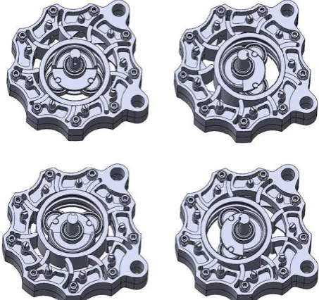
Fig. 1. Overview of the pneumatic engine designed by Di Pietro [13, 15, 16].
The air engine is used in industry and is a competition in relation to the electric motors. It is used mostly in dangerous explosive work atmospheres or in the vicinity of strong magnetic eclectic fields.
An important factor determining the profitability of its application is suitable efficiency and productivity. This article describes an innovative pneumatic engine designed by Angelo Di Pietro. According to his assumptions, this engine has 94.5% efficiency, and constant high torque. Additionally, this engine does not generate vibrations and has a very low friction, allowing the engine to operate at a low supply pressure of only 1 PSI (approx. 0.07 bar) [14].
Described engine has the following structure and work rules. Rotational motion is generated on a shaft positioned eccentrically in the cylindrical engine body. To the shaft there are attached specially arranged piston bearings, which exerts a force to interior cylinder, causing one sinusoidal rotation. The rotational movement of the cylinder forces expanding air in sequentially inflating air chambers. The tightness of the chambers provides cams with flat springs attached to the engine body. The cams closely adjacent to the cylinder. Below in Figure 1 is a plan view of the air engine designed by Angelo di Pietro. Figures show internal structure of the engine described above and also assembled structure ready to use [1-6].
2 Design of the engine air control
system
In the paper there will be described prototype design of the air engine having 9 working chambers. We will also show control system and do the simulation of the air flow in the engine.
2.1 3D model of the pneumatic engine
Below on figure 2 is a general view of designed air motor. There is chosen a structure having 9 working chambers.
Fig. 2. 3D model of the air motor: a) front view, b) rear view.
Fig. 3. Mounting cams in the engine.
We can see that by watching the front part of the engine (Fig. 2a), where are the springs attached in order to assist in internal piston oscillating movement. Figure 2b shows the back cover of the air engine. Figure 3 shows a method of mounting cams. It is important that the springs pressing the cams to the mentioned previously cylinder, should produce large enough force, that the cams do not lose contact with the cylinder at high speeds. Wrong selected force of the springs would cause the air flow between chambers and reduce engine efficiency. Cams clamp should be selected experimentally.
In order to minimize the adverse impact of friction between the internal components of the engine, there was care taken, that contact of the piston outer surface was not directly associated with the surface of the cylinder body. Occurring space helps keeping friction at the appropriate level. The rotary movement of the whole inner mechanism are provided by ball bearings. Designed structure ensures proper engine works. The next movement stages of the engine are shown below in Figure 4. There is showed how the piston and engine cams work, depending on rotation of the engine shaft.
Fig. 4. The subsequent stages of work pneumatic engine.
2.2 The control system project of the pneumatic engine
The control system is designed in that manner, so at any given time only one chamber of the engine is supplied, two neighbouring chambers are closed and the other ones are connected with the atmosphere.
On the top of rear engine cover is located air distributor. This cover has air supply threaded opening toward to the engine.
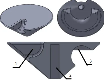
In the described engine air distributor has a conical shape (see Figure 6a). This element during rotation transmits compressed air to the respective consecutive chambers, and also receives air from the chambers already did not use.
Fig. 5. Engine control system: 1 - air channels cover, 2 - distributor, 3 - rear cover.
On Figure 6c shows a cross-sectional of the distributor, there can be distinguished inlet, outlet channels and shaft hole. The width of the inlet channel is expressed in degrees and is equal 30 degrees. This channel directs air from the connection of the engine body to the air channels.
Fig. 6. Distributor a) view from the top, b) view from bottom c) cross-section of the distributor; 1 - inlet channel, 2 - outlet channel, 3 - shaft hole.
The outlet channel is formed so as to minimize energy loss. This is possible because in the passive chambers there is no changes in pressure. The channel is located on the underside of the distributor and connects the supply channels in back cover with vent channels. The width of this channel is equal 220 degrees. Figure 6b shows a front view of the distributor.
In the rear part of the engine, centrally, are located notches of air channels, having its origin at the element base and end in engine working chambers. Those channels are used for filling and emptying of the working chambers. These channels are arranged symmetrically in a plane of circle and positioned at angle
of 23.3 degrees, respect to the mentioned base. Their size is 8 mm in diameter. Figure 7, below, shows a cross-section of the bonnet, where we can distinguish: 1 air channel, 2 air inlets, 3 insert, 4 vent channels.
Fig. 7. Cross section of the engine bonnet: 1 - air channel, 2 - air inlet channels, 3 - insert, 4 outlet channels.
An important parameter is the width of the distributor channel, expressed in degrees. It effects on cycle time length of the working chamber, which is translated into the air consumption, power, and torque of the engine. In describing design this value is set to 30° and was selected to assure some overlapping in air supply in cycles between adjacent chambers.
The angular distance between the inner edges of the air channel holes in the lid is equal 25.18°. This is so called dead zone. For instance, when the designer would make a mistake, and the width of the inlet channel would be smaller than the width of the zone, there would be a risk of engine stop in a position in which the individual start-up would be impossible.
Furthermore, in the work cycloramas there would be visible moments in which the engine would not produce torque, because none of the chambers would be air powered at that time. Such a break will result torque and work culture decrease of the engine.
The overlap between two air channels on the supply side is equal (see fig. 8):
x = 30° - 25,18° = 4,82° 26 (1)
This means that two adjacent chambers will be powered simultaneously by a time of 4.82° shaft rotation angle.
2.3 Air flow simulation
In order to illustrate air flow in the control components, we used CFD Flow Simulation software, which is extra added to basic SolidWorks software.
The first simulation shows a moment of the engine operating cycle. It is state, when one of the working chambers is air supply. The initial condition of engine work is to have total pressure equal 0.3MPa in inlet of the distributor body.
The resulting flow trajectories is shown in Figure 9. There is also illustrate the air speed, which increases dramatically in inlet channel to achieve maximum value in the working chamber.
Fig. 9. View of the trajectories of inlet air streams in cross-section through the air channel.
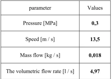
Flow Simulation CFD also allows us to estimate parameters such as mass and volume flow, which are crucial in engine work.
Table 1. Supply simulation parameters of working chamber.
parameter Values
Pressure [MPa] 0,3
Speed [m / s] 13,5
Mass flow [kg / s] 0,018
The volumetric flow rate [l / s] 4,97
The obtained values are shown in Table 1 and describes the conditions of the inlet channels from distributor. The second case shows the flow of outlet air. The figures 10 below show the simulation cycle, emptying the working chamber. The initial condition is the total pressure prevailing in the interior of engine, where the value is equal to 0.15MPa.
Fig. 10. View of the inlet air trajectory.
Fig. 11 shows, how the air way out from inside the engine through the vent channels, witch are located in the front cover. The main vent channel is the interior of the cylindrical piston.
3 Model research of pneumatic engine
control
In theory, presented control system would be able to manage air engine.
We discussed about that in chapter two. In case of building a model of the engine distributor, we try replacing its key part using numbers of pneumatic elements, lists below.
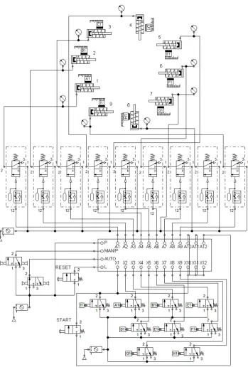
This example shows how a huge role does the distributor play and how many elements are needed to carry out its functions. It also allows us to find out the manner and results of its actions. In order to present the model of the control system, there was used FluidSIM program.The control system consists of following elements:
- single acting actuator with return spring (9 units), - sequential switcher "Quickstepper" (1 unit), - delay valve (9 units),
- 3/2 limit valve controlled by roll back spring (9units.), - 2/2 valve controlled by button with spring return
(2 units),
- 2/2 bistable valve controlled by buttons (2 units), - manometer (9 units),
- a source of compressed air with the FRL (3 units).
Working nine cylinders simulate the work chambers of the engine. Sequential switcher controlled from end valve signals acts as a distributor of compressed air. To get the effect of power supply cycles overlapping of subsequent chambers we used set of delay valves. Valves changes are followed by a signal from the sequential switch (see fig. 12).
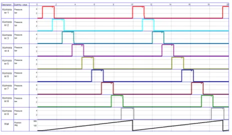
Fig. 13 shows cyclorama operation of the above system. We generated it in the “state diagram” block.
It is used to visualize the successive power cycles of chambers in the engine. The last line shows the angular position of the drive shaft and is added manually.
Fig. 13. Cyclorama of control system.
4 Summary and conclusions
Aim of the work, which was control system design of the air engine has been realized through the development of a 3D model. It was not an easy task, due to very small information about the dilates of the system, provided by the inventor of the engine. The proposal described in this paper, was preceded by a number of more or less successful prototype models. The second important aspect of this work was bunch of information about air flow, which take place in engine. We have shown pictures telling about air behaviour in inlet and outlet channels. In paper there are also figures describing interior concept of the pneumatic engine. We have written about cams and springs attached to them.
Finally, there have been showing model of directional valve building with numbers of pneumatic elements. We have focused on it, because in assumption it plays a crucial role in increasing efficiency and other desired parameters.
Good work of this model has been proved via cyclorama. All prototype designed, which we have presented here need to be checked and it will be next step in our research map.
References
1. P.A. Laski, J.E. Takosoglu, S. Blasiak, Robot. Auton. Sys. 72, 2015
2. P.A. Laski, Edited by Zolotarev I., Radolf V.
Proceedings of 22nd International Conference
on Engineering Mechanics 2016 (Academy of
Sciences of the Czech Republic, 2016)
3. D.S. Pietrala, Edited by Zolotarev I., Radolf V.
Proceedings of 22nd International Conference
on Engineering Mechanics 2016 (Academy of
Sciences of the Czech Republic, 2016)
4. M. Blasiak, Edited by Zolotarev I., Radolf V.
Proceedings of 22nd International Conference
on Engineering Mechanics 2016 (Academy of
Sciences of the Czech Republic, 2016)
5. J.E. Takosoglu, Edited by Zolotarev I., Radolf
V. Proceedings of 22nd International
Conference on Engineering Mechanics 2016
(Academy of Sciences of the Czech Republic, 2016)
6. J.E. Takosoglu, P.A. Laski, S. Blasiak, G. Bracha, D. Pietrala. Meas. Cont. 49, 2, 2016 7. L. Nowakowski, E. Miko, M. Skrzyniarz,
Edited by Zolotarev I., Radolf V. Proceedings of 22nd International Conference on
Engineering Mechanics 2016 (Academy of
Sciences of the Czech Republic, 2016)
8. H. Wisniewski, L. Plonecki, Proceedings of the 16th International Carpathian Control
Conference (ICCC), 2015
9. S. Blasiak, C. Kundera. Procedia Eng. 39 :315-326, 2012
10. E. Miko, L. Nowakowski, L. Procedia Eng. 39 (2012a)
11. G.F. Bracha. Edited by Zolotarev I., Radolf V.
Proceedings of 22nd International Conference
on Engineering Mechanics 2016 (Academy of
Sciences of the Czech Republic, 2016)
12. Z. Koruba, I. Krzysztofik, P. I. Mech. Eng. K-J. Multi-Body Dyn. 227, K1, 2013
13. Significant new rotary engine design runs on compressed air - Image 5 of 8. [13.05.2016]; Available from: http://www.gizmag.com/go/ 3185/picture/6137/
14. Engine Air. [20.06.2016]; Available from: http://www.engineair.com.au/
15. WWF 2 Degrees Project. [13.05.2016]; Available from: http://2degreesproject.com.au/. 16. Green Speed Motorcycle nouveau concept de