IJEDR1602242
International Journal of Engineering Development and Research (www.ijedr.org)1359
Grayscale Image Compression using Discrete Cosine
Transform
Mr. Amit D. Landge, Mr. S.A. Bagal, Mr. S. M Lichade
________________________________________________________________________________________________________
Abstract - Image compression is the reduction or elimination of redundancy in data representation in order to achieve reduction in storage and communication cost. [1] Discrete cosine transform (DCT) is computationally intensive algorithm it has lot of electronics application. DCT transforms the information time or space domain into frequency domain to provide compact representation, fast transmission and memory saving. [1]. DCT is very effective due to symmetry and simplicity. In this project we have used an intensive algorithmic flow for image compression, reconstruction of original image and error computation between original image and reconstructed image. This algorithmic flow used MATLAB-XILINX-MATLAB approach for mapping and loading process. For Grayscale image compression using DCT, initially selected 256*256 image and access or read this image for DCT computation, Then found that image pixels get reduced after DCT process, that means ultimately image get reduced. Similarly selection has modified for different images i.e. 64*64 and 8*8 images then got same compressed image after DCT image compression. After DCT computation here computed IDCT for reconstruction of image. Image reconstruction means whatever image pixels have compressed for a particular use need to decompress it also calculated, error image between original images and reconstructed image. In this project, the input image need to compress, that access/read into MATLAB and computed DCT and IDCT process over original image and calculated error between original image and reconstructed image. Similarly original image accessed into Xilinx through MATLAB using Mapping Process to implement DCT, IDCT and Error Image to compress and decompress a particular image. MATLAB is very much efficient and useful to take out each image pixels from original image also very helpful to load .txt file format from XILINX. The coding is simulated using XILINX 13.4 ISE and final error image shown through MATLAB 7.0.4.
Keywords- Discrete Cosine Transform (DCT), Inverse Discrete Cosine Transform (IDCT), VERILOG Hardware Descriptive Language (VERILOG HDL), Very High Speed Integrated Circuit Hardware Descriptive Language (VHDL), Joint Photographic Expert Group (JPEG).
________________________________________________________________________________________________________
I. INTRODUCTION
IJEDR1602242
International Journal of Engineering Development and Research (www.ijedr.org)1360
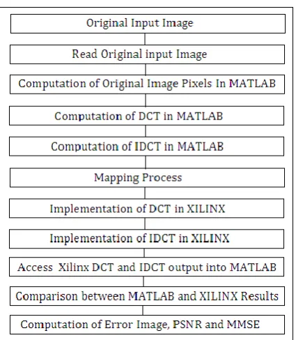
II. ALGORITHMIC FLOWThe algorithmic design flow gives us complete idea about project flow and this flow is useful to generate compression scheme. The design flow starts with the MATLAB environment for the computation of image pixels. First read one image into MATLAB as MATLAB is more suitable and efficient in case of image processing. There are different image formats ex. .jpeg, .png, .tif with different sizes as per image acquisition system.
As per project design flow, in this project have used MATLAB and XILINX both for image compression, ultimately used MATLAB-XILINX-MATLAB approach. Initially access/read original image into MATLAB for pixels computation so that we can able to apply these image pixels to Xilinx through Mapping Process between MATLAB and XILINX.
Block Diagram For Reconstruction Of Image In MATLAB Approach
Fig. 2 is for block diagram for Image Reconstruction it consists of DCT and IDCT in MATLAB approach. For image compression any image format here we can use i.e. JPEG, PNG, TIF image format. For image compression the ultimate aim behind it is, reduces to memory required for transmission and storage.
As we have seen earlier that access input grayscale image and compute image pixels from MATLAB, then followed image compression using DCT as it is effective for image compression. After computation of image compression with the help of IDCT algorithm then here generated reconstructed image. So to understand whether compression process if properly doing or not to check this it applied on different images for DCT and IDCT also and reconstruct images. Along with this we will take certain comparison process also between input and output also it will decide our compression strength. There is certain algorithm and formula to generate DCT and IDCT of the image. In DCT algorithm it reduces the size of pixels as explain further.
IJEDR1602242
International Journal of Engineering Development and Research (www.ijedr.org)1361
this case we have a question in mind that is it possible to generate compressed image which has very less pixel size, requires less area, reduced power so to verify it we will go for IDCT also we call it asFormula For DCT:-
The N *N Cosine Matrix C = {C( u, v )} is defined as, C( u, v ) = √(1/N) ---- u = 0 , 0 ≤ v ≤ N – 1
√(2/N) cos [( 2v +1)/2N ] --- 0 ≤ v ≤ N – 1 0 ≤ v ≤ N – 1 Then Finally we will get,
1. DCT = [ C ] * [ Image ] * [C’] 2. IDCT = [ C’ ] * [ DCT] * [C] where
c is DCT process matrix generated after computation of formula. c’ is the transpose of DCT process image matrix.
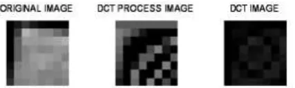
Computation MATLAB Result for 256*256 DCT Image Compression
MATLAB Result for 256*256 DCT Image Compression MATLAB Workspace Result for DCT Image Compression
MATLAB Workspace Result for DCT Image Compression
As we see above output Figure3 and Figure4 i.e MATLAB Result for 256*256 DCT Image Compression and MATLAB Workspace Result for DCT Image Compression, it is clear to all that when apply DCT process to input image, then image pixels get reduced and image get compressed. So DCT efficiently worked on image compression. After for more confirmation applied another image also of different size i.e for 64*64 and 8*8. By this way it is sure about image compression process.
MATLAB Image Result for 64*64 DCT Image Compression:-
Figure 7 - MATLAB Image Result for 64*64 DCT Image Compression.
MATLAB Workspace Result for DCT 64*64 Image Compression:-
IJEDR1602242
International Journal of Engineering Development and Research (www.ijedr.org)1362
Similarly figure5 for MATLAB Image Result for 64*64 DCT Image Compression and figure 6 for MATLAB Workspace Result for DCT 64*64 Image Compression. if applied 64*64 image and follow-up another DCT process to it then still we got compressed result for this image also. Finally decided to use 8*8 image.MATLAB result for 8*8 DCT Image Compression:-
Figure 9, MATLAB result for 8*8 DCT Image Compression
Command Window Output for 8*8 image:-
Figure 10, Command Window Output for 8*8 image.
In this project stepwise we have gone through different images i.e 256*256 image for DCT and IDCT and then for 64*64 image finally we have decided for 8*8 image then apply DCT process in MATLAB then finally it clears that pixel value get reduced and generate compressed image. So finally all works related to DCT for grayscale image compression of our project covered then also for more efficiency and depth so focused on XILINX approach also.
Block Diagram Form MATLAB–XILINX-MATLAB Comparison Approach For DCT Process:-
In this MATLAB–XILINX-MATLAB Comparison Approach for DCT and IDCT process, here initially, image is applied to MATLAB ,as that of previous one but here the processing is different than previous approach. In this approach, image applied to MATLAB. After reading image into MATLAB using syntax imread (‘image.fomat’);. Image just enter into the MATLAB and these image pixels visible at the command window and workspace. So after this it is possible to process on these pixels. In t his MATLAB–XILINX-MATLAB Comparison Approach, initially whenever the image pixels, initially accessed into MATALB and these are stored in workspace. In this approach, there is a need of DCT computation to compress an image, so for this there is a need of DCT process matrix. For creation of DCT process matrix there is a need of computation of formula are as follows. As shown in the formula for DCT, This formula need to compute in MATALB for DCT creation for that there is a need to follow DCT formula and equation-1 and just put that result into MATALB command window. Then after DCT computation there is a need to focus on IDCT i.e. there is a need to focus on decompression of compressed, that means ultimately need to reconstruction of image from the compressed image. These two DCT and IDCT results stored for comparison purpose.
IJEDR1602242
International Journal of Engineering Development and Research (www.ijedr.org)1363
multiplication as explained in equation 1 and 2 then finally output results generated is DCT and IDCT of XILINX. These two results are stored in .txt files that are ‘output.txt’ and ‘output_iDCT.txt’ which consists of DCT and IDCT results from XILINX. Finally comparison followed between DCT / IDCT of MATLAB and XILINX. Finally generated result in image for i.e error image berween DCT nad IDCT of MATLAB and XILINX.The result is followed because of three things
MATLAB is more familiar and functional in case of image processing.
XILINX has a advantage, it requires less are and power, with high speed because of HDL. Communication possible between MATLAB and XILINX.
Xilinx (Verilog Hdl) Implementation of DCT And IDCT:- FOR IMAGE 1:-
By using Mapping Process, MATLAB and XILINX communication is possible. As shown above simulation result it is generated from XILINX which consists of IDCT results. This IDCT results is generated by Matrix Multiplication between input image and DCT process image. These two matrix taken from MATLAB by communication process between MATLAB and XILINX. The matrix multiplication is done by formula as
1. DCT = [ C ] * [ Image ] * [C’] --- (1). 2. IDCT = [ C’ ] * [ DCT] * [C] --- (2).
4.2.1. HDL SYNTHESIS REPORT
HDL synthesis report for XILINX Approach Components Required Quantity Macro Statistics RAMs 4
Multipliers 58
Adders/Subtractors 104
Registers 1600
Latches 8
Comparators 7
Multiplexers 39
Tristates 3072
Xors 1056
COMPARISON BETWEEN MATLAB DCT/IDCT AND XILINX DCT/IDCT FOR IMAGE 1
IJEDR1602242
International Journal of Engineering Development and Research (www.ijedr.org)1364
4.2.2. MATLAB COMMAND WINDOW OUTPUT
Result 1- From MATLAB Command Window Output For Comparison Process
MATLAB Command Window Output:-
MATLAB Command Window Output For Image 1:- DCT Output by MATLAB
DCT_in =
536.2500 17.6803 -1.3994 -43.5731 -9.7500 41.6034 7.0740 -12.5926
-3.5855 41.5357 -8.7559 5.4580 -14.0499 6.6515 -11.6590 16.2443 -240.1252 -94.3409 23.2723 42.7757 4.1026 -53.8482 -1.3187 49.4598 5.1191 -85.6652 1.3136 21.5858 -18.0251 -18.0274 -38.2983 -29.7056 77.0000 74.2945 -42.1910 -34.7732 3.0000 28.6175 8.5464 -40.3956 23.0537 80.2954 -21.0220 9.0410 36.7736 -5.0628 -10.1564 1.8418 -23.1178 -32.2886 32.4313 17.8118 -21.4530 -5.1611 -11.0223 12.0388 -80.3171 -101.6873 -13.0140 4.8415 10.1130 3.3683 10.4752 -34.5587
1. DCT Output by VERILOG
DCT_out =
534 16 -3 -45 -11 39 6 -14 -4 41 -9 5 -15 6 -12 16 -240 -95 22 42 4 -54 -2 49 5 -86 1 22 -18 -19 -39 -30 76 73 -43 -35 2 28 8 -41 23 80 -22 9 36 -5 -11 1 -24 -33 32 17 -22 -5 -12 11 -81 -102 -14 4 9 3 10 -35
2. DCT
Error due to Quantization: 8.11 %, PSNR:21.82,
MMSE:0.08
3. IDCT Output by MATLAB:-
iDCT_in =
IJEDR1602242
International Journal of Engineering Development and Research (www.ijedr.org)1365
71.0189 41.9949 74.0041 54.9986 40.0022 49.9998 68.0013 61.0006208.9934 183.0018 218.9986 218.0005 89.9992 61.0001 53.9995 38.9998 57.0102 84.9972 105.0022 172.9992 42.0012 124.9999 108.0007 111.0003 67.9990 94.0003 62.9998 56.0001 64.9999 85.0000 125.9999 100.0000 30.0059 17.9984 19.0013 48.9995 61.0007 47.9999 38.0004 71.0002 34.0026 16.9993 58.0006 23.9998 26.0003 35.0000 37.0002 59.0001
4. IDCT Output by VERILOG
iDCT_out =
17 40 19 34 48 42 52 32 45 42 70 21 47 39 68 53 71 42 74 55 40 50 68 61 209 183 219 218 90 61 54 39 57 85 105 173 42 125 108 111 68 94 63 56 65 85 126 100 30 18 19 49 61 48 38 71 34 17 58 24 26 35 37 59
5. IDCT
Error due to Quantization: 0.02 %. PSNR:76.35.
MMSE:0.00.
XIILINX IMPLEMENTATION FOR DCT AND IDCT:- FOR IMAGE 2:-
COMPARISONOF IMAGE BETWEEN MATLAB DCT/IDCT AND XILINX DCT/IDCT FOR IMAGE 2:-
REFERENCES
[1] R. Uma, FPGA Implementation of 2-D DCT for JPEG Image Compression, Electronics and Communication Engineering Rajiv Gandhi College of Engineering and Technology, Pondicherry, India, International Journal Of Advanced Engineering Sciences And Technologies (IJAEST) , Vol No. 7, Issue No. 1, 001 – 009, 2011.
[2] VijayaPrakash and K.S.Gurumurthy, A Novel VLSI Architecture for Digital Image Compression Using Discrete Cosine Transform and” Quantization IJCSNS September 2010.
[3] Jongsun Park Kaushik Roy, A Low Complexity Reconfigurable DCT Architecture to Trade off Image Quality for Power Consumption Received:2 April 2007 / Revised: 16 January 2008 / Accepted: 30 April 2008 /Published online: 3 June 2008. [4] Jongsun Park Kaushik Roy A Low Complexity Reconfigurable DCT Architecture to Trade off Image Quality for Power
Consumption Received:2 April 2007 / Revised: 16 January 2008 / Accepted: 30 April 2008 /Published online: 3 June 2008. [5] Peng Chungan, Cao Xixin, Yu Dunshan, Zhang Xing, ―A 250MHz optimized distributed architecture of 2D 8x8 DCT, 7th
International Conference on ASIC, pp. 189 – 192, Oct. 2007.
IJEDR1602242
International Journal of Engineering Development and Research (www.ijedr.org)1366
[7] Roger Endrigo Carvalho Porto, Luciano Volcan Agostini ―Project Space Exploration on the 2-D DCT Architecture of aJPEG Compressor Directed to FPGA Implementation‖ IEEE, 2004.
[8] S. A. White, Applications of distributed arithmetic to digital signal processing: a tutorial review, IEEE ASSP Magazine, vol.6, no.3, pp.4- 19, Jul.1989.
[9] W. Pennebaker and J. Mitchell, JPEG Still Image Data Compression Standard, Van Nostrand Reinhold, USA, 1992.
[10]Ahmed N, Natarajan T, Rao KR (1974). Discrete Cosine Transform. IEEE Trans. Comput., C-23(1): 90-93. Cintra RJ, Bayer FM (2011). A DCT Approximation for Image
[11]Dibyayan DS, Anshu K, Pushplata (2011) FPGA Based Hardware Realization of DCT- II Independent Update Algorithm for Image Processing Applications. Int. J. Computer. Engg. Manage Danian G, Yun H, Zhigang CA (2004). New Cost-Effective VLSI Implementation of a 2-D Discrete Cosine Transform and its Inverse. IEEE Trans. Circuits Syst. Video Technol., 14(4): 405-415.
[12]The International Telegraph and Telephone Consultative Committee (CCITT). Information Technology – Digital Compression and Coding of Continuous-Tone Still Images – Requirements and Guidelines. Rec. T.81, 1992.
[13]W. Pennebaker and J. Mitchell. JPEG Still Image Data Compression Standard, Van Nostrand Reinhold, USA, 1992.
[14]Junqing Chen, Kartik Venkataraman, Dmitry Bakin, Brian Rodricks, Robert Gravelle, Pravin Rao, Yongshen Ni, ―Digital Camera Imaging System Simulation,IEEE Transactions on Electron Devices,vol.56(11), pp.2496 – 2505, Nov. 2009.
[15]Roger Endrigo Carvalho Porto, Luciano Volcan Agostini ,Project Space Exploration on the 2-D DCT Architecture of a JPEG Compressor Directed to FPGA Implementation IEEE, 2004 .
[16]Jin-Maun Ho, Ching Ming Man, ―The Design and Test of Peripheral Circuits of Image Sensor for a Digital Camera, IEEE International Conference on Industrial Technology, 2004. IEEE ICIT '04, vol.3, pp.1351 – 1356, 8-10 Dec. 2004.