Investigation of the compressed baryonic matter at the GSI
ac-celerator complex
V.P.Ladygin1,,T.O.Ablyazimov1,P.G.Akishin1,E.P.Akishina1,2,V.P.Akishina1,M.I.Baznat1,3, I.V. Boguslavsky1, V.N. Borshchov4, A.V. Bychkov1, D.V. Dementiev1, O.Yu. Derenovskaya1, V.V. Elsha1, K.K. Gudima1,3, Yu.V. Gusakov1, S.N. Igolkin5, A.Yu. Isupov1, V.V. Ivanov1, G.D.Kekelidze1,A.N.Khrenov1,P.I.Kisel1,2,M.G.Korolev6,G.E.Kozlov1,7,V.A.Kramarenko1, P.K.Kurilkin1, N.B. Ladygina1,V.M. Lysan1, A.I. Malakhov1, I.P.Martinovsky8, M.M.Merkin1,6, Yu.A.Murin1,S.S. Parzhitsky1,V.A. Penkin1,S.M.Piyadin1,M.A. Protsenko1, A.A.Savenkov1, A.V. Shabunov1, A.I. Shafranovskaya1, A.D. Sheremetiev1, O.G. Tarasov1, I.T. Tymchuk4, N.I.Zamiatin1,A.I.Zinchenko1, andE.V.Zubarev1
1Joint Institute for Nuclear Research, Dubna, Russian Federation 2Institut für Kernphysik, Goethe Universität Frankfurt, Frankfurt, Germany 3Institute of Applied Physics of ASM, Kishinev, Moldova
4National Science Center, Kharkov Institute of Physics and Technology, Kharkov, Ukraine 5State University of St.Petersburg„ St.Petersburg, Russian Federation
6Skobeltsyn Institute of Nuclear Physics of Moscow State University, Moscow, Russian Federation 7Frankfurt Institute for Advanced Studies, Goethe-Universität Frankfurt, Frankfurt, Germany 8State Enterprise PLANAR, Minsk, Belarus
Abstract. The Compressed Baryonic Matter (CBM) experiment at FAIR will play a unique role in the exploration of the QCD phase diagram in the region of high net-baryon densities, because it is designed to run at unprecedented interaction rates. High-rate oper-ation is the key prerequisite for high-precision measurements of multi-differential observ-ables and of rare diagnostic probes which are sensitive to the dense phase of the nuclear fireball. The goal of the CBM experiment at SIS100 (√sNN=2-4.9 GeV) is to discover
fundamental properties of QCD matter, namely, the equation-of-state at high density as it is expected to occur in the core of neutron stars, effects of chiral symmetry, and the phase structure at large baryon-chemical potentials (μB≥500 MeV).
We are focusing here on the contribution of JINR to the CBM experiment: design of the superconducting dipole magnet; manufacture of the straw and micro-strip silicon detec-tors, participation in the data taking and analysis algorithms and physics program.
1 Introduction
The investigation of nuclear matter at extreme conditions, i.e. at high temperatures and/or at high baryon densities, is one of the most challenging fields of modern physics. The major efforts are
devoted to the exploration of the phase diagram of strongly interacting matter using heavy-ion colli-sions at relativistic energies. While the experiments at the Relativistic Heavy Ion Collider (RHIC) at BNL and at the Large Hadron Collider (LHC) at CERN focus on the study of high temperatures, the Compressed Baryonic Matter (CBM) experiment at the future FAIR accelerator will concentrate on the investigation of highest baryon densities at still moderate temperatures. In particular, the CBM re-search program aims at the exploration of the structure of high density matter including the question of deconfinement and chiral phase transitions. The theoretical description of physics at high net baryon densities within the fundamental theory of strong interaction, Quantum Chromodynamics (QCD), is still strongly evolving and the scientific progress in "strong" nonperturbative QCD is driven by new experimental data. Figure 1 illustrates the phases of strongly interacting matter and their boundaries in a diagram of temperature versus baryon chemical potential [1]. The CBM experiment will enter a new era with diagnostic probes never measured before in the FAIR energy range, and thus has a unique research potential.
The high-intensity heavy-ion beams of the future FAIR accelerators, together with the planned Compressed Baryonic Matter (CBM) experiment, offer excellent possibilities to produce and to in-vestigate baryonic matter at highest densities in the laboratory. The research program comprises the study of the structure and the equation-of-state of baryonic matter at densities comparable to the ones in the inner core of neutron stars. This includes the search for the phase boundary between hadronic and partonic matter, the critical endpoint, and the search for signatures for the onset of chiral symme-try restoration at high net-baryon densities [2, 3].
Figure 1. Sketch of the phase diagram for strongly interacting matter [1].
Figure 2. The CBM experimental setup together with HADES [4].
The most promising probes to study the high density QCD matter at SIS100 energies are the flow of identified particles, event-by-event fluctuations, strangeness production including hypernuclei and metastable strange objects, dileptons, charm production near threshold.
The collective flow of hadrons is driven by the pressure gradient created in the early fireball and provides information on the dense phase of the collision. The CBM experiment will therefore dramat-ically improve the data situation by measuring the the flow of identified particles in the FAIR energy range, including multi-strange hyperons and dileptons.
Event-by-event fluctuations of conserved quantities such as baryon number, strangeness and elec-trical charge can be to provide insight into the properties of matter created in high-energy nuclear collisions. Lattice QCD calculations suggest that higher moments of these distributions are more sensitive to the phase structure of the hot and dense matter created in such collisions.
statis-tical significance the production and propagation of heavy strange and anti-strange baryons up toΩ+ hyperons in dense nuclear matter. Also excited hyperon states can be identified. The CBM experiment at SIS100 will also measure hydrogen and helium hypernuclei with large statistics. The discovery of (double-) Lambda hypernuclei and the determination of their lifetimes will provide information on the hyperon-nucleon and hyperon-hyperon interactions, which are essential ingredients for the un-derstanding of the nuclear matter equation-of-state at high densities, and, hence, of the structure of neutron stars.
Dileptons emitted in collisions of heavy ions offer the unique opportunity to investigate the mi-croscopic properties of strongly interacting matter. Virtual photons are radiated offduring the whole time evolution of a heavy- ion collision. Once produced, they decouple from the collision zone and materialize as muon or electron pairs. A very important part of the CBM research program is the possibility to study both di-electron and di-muon pairs production.
Charm production will be studied for the first time at beam energies close to production threshold. At these energies, the formation time of charmonium is small compared to the lifetime of strongly in-teracting system created in high-energy nuclear collisions. Therefore, CBM will study the interactions between fully formed J/Ψand the dense medium with appropriate counting statistics and systematics. Systematic measurements of charmonium in p+A collisions with varying target mass numberA at proton energies up to 30 GeV will shed light on the charmonium interaction with cold nuclear matter and constitute an important baseline for measurements in nuclear collisions.
2 CBM detector
The CBM detector has been designed as a multi- purpose device which will be capable to measure hadrons, electrons and muons in elementary nucleon and heavy-ion collisions over the full FAIR beam energy range. In order to perform high-precision multi-differential measurements of rare probes the experiment should run at event rates of 100 kHz up to 10 MHz for several months per year. To filter out weakly decaying particles like hyperons orDmesons, no simple trigger signal can be generated. Instead, the full events have to be reconstructed, and the decay topology has to be identified online by fast algorithms running on a high-performance computing farm hosted by the GSI Green IT cube. To utilize maximum rates, the data acquisition is based on self-triggered front-end electronics.
The CBM experimental setup together with HADES [4] is shown in figure 2. Each setup has its own target. During HADES operation, the beam will be stopped by a beam dump in front of the CBM detector, comprises the following components:
• a Superconducting Dipole Magnet,
• a Micro Vertex Detector (MVD) consisting of four layers of silicon monolithic active pixel sensors,
• a Silicon Tracking System (STS) based on double- sided silicon micro-strip sensors arranged in eight stations inside the magnetic field,
• a Time-of-Flight wall (TOF) based on Multi- Gap Resistive Plate Chambers (MRPC) with low-resistivity glass essential for high-rate operation,
• a Ring Imaging Cherenkov (RICH) detector comprising a CO2radiator, and aUVphoton detector realized with multi-anode photomultipliers for electron identification,
• a Transition Radiation Detector (TRD) for pion suppression, particle tracking, and identification using specific energy loss,
• a Projectile Spectator Detector (PSD) for event characterization,
• a First-Level-Event-Selection (FLES) system for online event reconstruction and selection. For muon measurements, the RICH will be exchanged by the MuCh which is shown in a parking position to the right of the beam axis in figure 2. The preparation of the experiment is well advanced. According to the schedule, the CBM experiment will be ready to take the first beams from SIS100 in 2022.
3 JINR contribution to CBM
The contribution of JINR to the CBM experiment is the following: design of the superconducting dipole magnet; manufacture of the straw and micro-strip silicon detectors, participation in the data taking and analysis algorithms and physics program at FAIR [5].
3.1 Superconducting Dipole Magnet
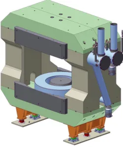
TheH-type superconducting magnet of the CBM experiment is designed to provide a vertical mag-netic field with bending power of 1 T·m over a length of 1 m from the target. A perspective view of the magnet with the support is presented in figure 3. The magnet yoke consists of two conical poles and two horizontal and two vertical parts to close a flux return. Two cylindrical superconducting coils will be installed in their respective cryostats and will be cooled separately by helium bath based cooling system like the SAMURAI magnet at RIKEN [6]. The maximum energy storage is evaluated as 5.15 MJ when the operating current of the CBM magnet is rated at 686 A. The design of coil for the CBM magnet is based on the design of the Super-FRS dipole [7]. Each coil has 1749 turns and 53 layers. The superconducting wire is aNb/T iwire. The conductor insulation consists of 0.1 mm polyimide type and 0.2 mm glass fiber (G10) material. Each layer is additionally insulated from the others by three layers of 0.1 mm fiber glass fabric with epoxy resin. The detailed description of the CBM magnet can be found in [8].
Figure 3.Perspective view of the CBM dipole mag-net with the support.
Figure 4.3D model of cryostats with the feed boxes.
helium vessel, thermal shield and vacuum vessel. The vacuum vessel has flanges for connecting to the external cryogenic line, the turbo molecular pump, two 1000 A current leads, the multipin feedthrough with plug connectors, the safety valve of the vessel and the warm multi-purpose helium line (quench gas collection). Also, the vacuum vessel and the heat shield have a large diameter access hole to connect pipes of the external cryogenic line with helium pipes of coils. All these connections are made by means flexible metal hoses.
Internal helium vessel containing 10 l of liquid helium has four flanges. The high voltage feedthrough CF40HC8-CE-SST95 is connected to the top flange. It is necessary for passing su-perconducting wires with vaporized helium to current leads. The second flange is for the multi-pin feedthrough with plug connectors. The third flange is connected to the helium return line. The last flange is connected through built-in safety valve to the warm multi-purpose helium line (for quench gas collection) [9].
Figure 5. 3D quench simulation for the CBM mag-net: magnet current, coil voltage, magnet voltage and "hot spot" temperature. (Rd =2.1Ω).
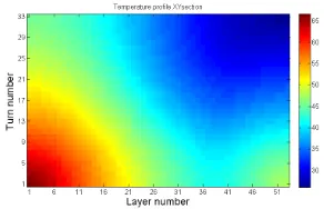
Figure 6. 3D quench simulation for the CBM mag-net: temperature distribution in the coil cross section. (Rd=2.1Ω).
The 3D quench calculations have been performed for two quench protection schemes. One of them is based on the extraction of the energy stored in CBM magnet via external dump resistor of 1.9-2.1 Ohm. In this case around 80-86 % of the energy stored in the magnet (∼5 MJ) will be dissipated outside of the cryostat [10, 11]. Figure 5 demonstrates magnet current, coil voltage, magnet voltage and "hot spot" temperature when the 2.1 Ohm dump resistor is used. The maximum “hot-spot” tem-perature is about 70 K. Figure 6 represents the temtem-perature distribution in the cross section of the coil winding. The other quench protection scheme is based on the heating of the superconducting coil [12]. The quench protection system based on the energy extraction via dump resistor with resistance of 1.9-2.1 Ohm was chosen for CBM magnet due to the lower temperature gradient in the coil.
The electromagnetic calculation has been performed for the CBM dipole magnet with the distance between the poles of 1550 mm, what is 150 mm larger than required by TDR [8]. The bending power of enlarged magnet is about 0.88 T·m with the nominal operating current. The current must be increased by∼25% to reach the field integral of∼1 T·m [8]. However, in this case the reaction forces in the coil supports will increase by∼38%, what would require to change significantly the magnet design [13]. The electromagnetic calculation for the distance between the poles of 1440 mm is in progress.
3.2 Straw chambers for muon detector
track the particles through a hadron absorber system, and to perform a momentum- dependent muon identification.
This concept is realized by segmenting the hadron absorber in several layers, and placing triplets of tracking detector planes in the gaps between the absorber layers. The absorber/detector system is placed downstream of the Silicon Tracking System which determines the particle momentum. In order to reduce meson decays into muons the absorber/detector system has to be as compact as possible. The final design of the muon detector system for SIS300 consisting of 6 hadron absorber layers (60cm carbon and iron plates of 2×20 cm, 30 cm, 35 cm and 100 cm thickness) and 18 gaseous tracking chambers located in triplets behind each absorber slab is shown in figure 7. The identification of a muon depends on its momentum which varies with the mass of the vector mesons and with beam energy.
Figure 7. SIS100 CBM muon system configuration with straw tubes in two last detector stations.
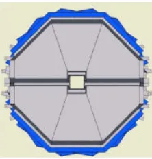
Figure 8.Schematic view of the MuCh station with three straw chambers.
The challenge for the muon chambers and for the track reconstruction algorithms is the very high particle density up to a maximum of 0.3 hits/cm2per central event in the first detector layers after the first absorber. For a reaction rate of 10 MHz this hit density translates into a hit rate of 3 MHz/cm2. However, rather low particle multiplicities for the last detection layers (behind last muon absorbers) allows to use straw tubes. For MuCh use, an assembly of straw stations containing 12 double layers modules, each consisting of about 1184 straws, is in development. Each straw station contains three identical octagonal chambers measuring X and two rotated (+10◦, -10◦) coordinates of a passing charged particle. Each chamber consists of two identical modules with some overlap between them to avoid dead regions. The chambers are having inner holes for the beam pipe with a diameter of 43 cm [14]. The schematic view of the MuCh station with three straw chambers is shown in figure 8.
The main advantage of the straw tubes is the high speed with good spatial resolution from the point of view of the tracking of the detected particle. Sensitive time of the detector is not exceeding 80 ns and a spatial resolution is better than 200μm at high performance up to the hit rate of 5-10 MHz/channel. The experience of the manufacture of the ATLAS TRT [15, 16], the COMPASS tracker [17] at CERN and the straw chambers for SVD-2 experiment [18] at U70 accelerator in Protvino confirms the high performance of the detectors.
3.3 Silicon Tracker System
The task of the STS [20] is to provide track reconstruction and momentum determination of charged particles. The multiplicity of charged particles is about 700 per event within the detector acceptance. The layers are located downstream of the target at distances between 30 cm and 100 cm inside the Superconducting Dipole Magnet with∼1 T·m magnetic field integral. The required momentum res-olution is of the order ofΔp/p∼1%. This performance can be achieved with an ultra-low material budget of the stations, imposing particular restrictions on the location of power-dissipating front-end electronics in the fiducial volume. The concept of the STS tracking is based on silicon micro-strip sen-sors mounted onto lightweight mechanical support ladders [21]. The sensen-sors will be read out through multi-line micro-cables with fast electronics at the periphery of the stations where cooling lines and other infrastructure can be placed. The micro-strip sensors will be double-sided with a stereo angle of 7.5◦, a strip pitch of 60μm, strip lengths between 20 and 60 mm, and a thickness of 300μm of silicon. The micro-cables will be built from sandwiched polyimide-Aluminum layers of several 10μm thick-ness [22]. 8 layer station will consist of 896 sensor modules from CiS (Germany) and Hamamatsu (Japan) manufactors. These modules will be assembled into 106 carbon ladders [21].
About third of the CBM STS sensor modules will be assembled to populate 60 ladders for the first four stations within the signed JINR-FAIR-CBM Collaboration Contract. JINR STS- team is working on testing of components of the modules, on the development of assembly methods, on the multiple fixtures and custom designed ladder assembly devices together with industrial partners in Ukraine and Belarus [23]. Module assembling site at JINR LHEP was fully equipped financed jointly by JINR and BMBF. Quality assurance group modified the standard automatic probe station developed for scanning the wafers with chips into a automatic device for testing double-sided micro-strip sensors. The first test station with a silicon micro-strip sensor for the in-beam tests at Nuclotron is designed, assembled and put to operation in the lab. It is ready for the installation in the STS test area at Nuclotron [24].
3.4 Methods, algorithms and software for fast event reconstruction
Event reconstruction, being a key part of success of the experiments, is the most complicated and time consuming task of the data analysis. In addition, in some cases a full on-line event reconstruction and selection must be done on-line at the high-level trigger stage. All of the above mentioned makes necessary to develop fast and efficient methods, algorithms and software for data analysis and to optimize them for running on an advanced high performance computing cluster.
JINR (LIT) takes part in the development of the algorithms and software for track and ring re-construction in MuCh, TRD, RICH, MVD detectors as well as global track rere-construction. Track reconstruction methods are based on the track following and Kalman filter procedures. Ring recon-struction is based on the Hough Transform method. The clustering algorithms in MVD, STS and MuCh have been developed and included into simulation [25].
4D event reconstruction using the time slices information has been developed. The time-slice border problem effect of possible event splitting in the border region of neighbouring time-slices was investigated. Multi-vertex analysis reconstruction for the case of merged events which can not be resolved with the time measurement use only has been performed using the event topology [26].
First Level Event Selection software is under development using different manycore CPUs and GPUs platforms [27].
Two methods for the fast and reliable electron–positron identification using the energy losses of charged particles in the TRD (see figure 9) have been developed: an artificial neuron network (ANN) and a modified goodness-of-fit criterionωk
E, keV
Δ
0 10 20 30 40
Entries
2
10
4
10 π+/- (dE/dx)
(dE/dx + TR) +/-e
Figure 9.Energy loss distributions of pions (dashed line) and electrons (solid line) in the TRD
output
4 6 ω∼
0 0.5 1
Entries
1
2
10
4
10
Figure 10.Distribution ofωk
nrandom values for
pi-ons (solid line) and electrpi-ons (dashed line) [28].
The the vector finding method [29] is based on building vectors for each MuCh station sepa-rately and matching them to each other and to STS tracks through the absorbers. Presumably, such an approach should better handle a heterogeneous tracking environment (GEM and straw tube detec-tors) and offer higher flexibility with respect to algorithm tuning as compared with a track following method. Moreover, this algorithm is naturally parallelizable and can be used for the triggering appli-cation. The results were obtained for different SIS100 MuCh configurations (see figure 7) using the vector finding [30]. It has been shown good performance of the algorithm both for 4 double layers and 3 double layers of straw tubes for 2 last station of MuCh detector.
JINR contributes also to the CBMRoot and to the concept of CBM Databases [31] developments.
3.5 Simulation for physics at SIS100
. The measurements of the yields of light nuclei, which are formed by the coalescence of individual nucleons is an alternative to HBT interferometry method to extract the information on the source at freeze-out.
Figure 11. y−pT distribution for deuterons from
Au+Aucentral collisions at 4A·GeV [32].
Figure 12.Transverse mass distribution for deuteron produced in theAu+Aucentral collisions at 4A·GeV [32].
The transverse momentum- rapidity,y−pT, distribution for deuterons from theAu+Aucentral
col-lisions at 4A·GeV [32] is presented in figure 11. The dominant reaction mechanism is a coalescence. The 1/mt·d2N/dmtdydistribution for deuterons from theAu+Aucentral collisions at 4A·GeV [32]
for further analysis of the coalescence factorB2. The calculated atpt=0 value of coalescence factor B2(mt=m0)=(3.1±0.2)·10−3GeV2is larger by one order of magnitude than that measured in central
Pb+Pbcollisions at SPS [33]. TheB2factor increases exponentially as a function of the transverse mass differencemt−m0with the inverse slopeT ≈1.56 GeV [34].
Feasibility studies of the J/Ψ→e+e−and J/Ψ→μ+μ−decays reconstruction have been performed [35]. It has been shown that one can expect∼60 and∼5·103J/Ψ→e+e−decays detected per hour at 10 MHz of theAu+Aucollisions at 10 and 25 A·GeV, respectively. The signal to background ratio is
S/N0.18 and 7.5 at 10 and 25 A·GeV, respectively. The feasibility to measure J/Ψ→e+e−inpCand
pAucollisions has been also demonstrated.
3.6 Beam tests
JINR participate in the data analysis of the beam tests results for the RICH and TRD prototypes.
htemp Entries 7039 Mean 196.4 RMS 93.68
Vpp, mV
0 100 200 300 400 500
Number of events
0 50 100 150 200 250 300 350 htemp Entries 7039 Mean 196.4 RMS 93.68
Figure 13.The amplitude of the scintillation detector irradiated by the neutron fluence of∼7.5·107n/cm2.
2 Fluence, n/cm
50 100 150 200 250 300 350 400 450
6 10 × V, mV 0 20 40 60 80 100 120 140 160 180 200
Figure 14. The dependence of the signal amplitude from the scintillation detector as a function of the neutron fluence.
The radiation hardness of APDs from different manufactures has been investigated at NPI in ˇRež [36] for PSD readout development. Further studies have been performed with a 10 channels scin-tillation detector prototype developed at LHEP JINR [37]. A prototype was irradiated using quasi-monoenergetic secondary neutron beam from cyclotron facility U120M at NPI in ˇRež. The signal from one of the scintillation detector in the beginning of the irradiation (after 7.5·107 n/cm2 of the 1 MeV neutron fluence) is shown in figure 13. The decrease of the SiPM signal with the irradiation dose is demonstrated in figure 14. The signal decreases by a factor of∼1.4, while the intrinsic noise increases approximately twice after irradiation with the 1 MeV neutron fluence of 4.2·108n/cm2. The electronics demonstrated the stable operation during the irradiation.
4 Conclusions
• The CBM research program aims at the exploration of the structure of high density matter. For these purpose the advanced experimental setup will be build for high counting rate conditions expected at FAIR.
• The major goal for 2016-2020 is to construct CBM detector to be ready for data taking at SIS100.
• JINR participates in the CBM project very actively and its contribution is large.
References
[1] K. Fukushima and T. Hatsuda, Rept. Prog. Phys.74, 014001 (2011) [2] B. Friman et al., Lect.Notes Phys.814, 1 (2011)
[3] S. Chattopadhyay et al., e-Print: arXiv:1607.01487 [nucl-ex] [4] G. Agakishiev et al., Eur.Phys.J. A41, 243 (2009)
[5] P. Kurilkin et al., Int.J.Mod.Phys. Conf. Ser.39, 1560098 (2015) [6] H. Sato et al., IEEE Trans. Appl. Supercond.23, 4500308 (2013) [7] L.Z. Ma et al., IEEE Trans. Appl. Supercond.22, 9502104 (2012)
[8] The CBM Collaboration,Technical Design Report for the CBM Superconducting Dipole Magnet, GSI-2015-02000 (2013)
[9] Yu.V. Gusakov et al.,CBM Progress Report 2015(GSI, Darmstadt, 2016) 9 [10] P. Kurilkin et al.,CBM Progress Report 2013(GSI, Darmstadt, 2014) 8 [11] P. Kurilkin et al., J.Phys.Conf.Ser.742, 012017 (2016)
[12] P. Kurilkin et al.,CBM Progress Report 2015(GSI, Darmstadt, 2016) 11 [13] Yu.V. Gusakov et al.,CBM Progress Report 2015(GSI, Darmstadt, 2016) 8
[14] The CBM Collaboration,Technical Design Report for the CBM Muon Chambers, GSI-2015-02580 (2015)
[15] Yu.V. Gusakov et al., Phys.Part.Nucl.41, 1 (2010) [16] A.S. Boldyrev et al., Instrum.Exp.Tech.55, 323 (2012)
[17] V.N. Bychkov et al., Nucl.Instrum.Meth. in Phys.Res. A556, 66 (2006) [18] S.G. Basiladze et al., Instrum.Exp.Tech.55, 336 (2008)
[19] V.D. Peshekhonov et al., Phys.Part.Nucl.Lett.9, 172 (2012)
[20] The CBM Collaboration,Technical Design Report for the CBM Silicon Tracking System, GSI-2013-05499 (2013)
[21] S. Igolkin et al.,CBM Progress Report 2014(GSI, Darmstadt, 2015) 48 [22] V.M. Borshchov et al.,CBM Progress Report 2015(GSI, Darmstadt, 2016) 36 [23] A. Sheremetev et al.,CBM Progress Report 2015(GSI, Darmstadt, 2016) 40
[24] D. Dementyev and Yu. Murin,CBM Progress Report 2015(GSI, Darmstadt, 2016) 31 [25] G. Kozlov, et al.,CBM Progress Report 2012(GSI, Darmstadt, 2013) 91
[26] V. Akishina, et al.,CBM Progress Report 2012(GSI, Darmstadt, 2013) 93 [27] V. Akishina, et al.,CBM Progress Report 2012(GSI, Darmstadt, 2013) 92
[28] O.Yu. Derenovskaya and V.V. Ivanov,CBM Progress Report 2012(GSI, Darmstadt, 2013) 96 [29] P. Billoir et al., Nucl.Instrum.Meth. in Phys.Res. A241, 115 (1985)
[30] A. Zinchenko et al.,CBM Progress Report 2015(GSI, Darmstadt, 2016) 121 [31] E.P. Akishina et al.,CBM Progress Report 2015(GSI, Darmstadt, 2016) 123 [32] V.D. Toneev et al., Nucl.Phys. A519, 463C (1990)
[33] S.V. Afanasiev et al., Phys.Lett. B486, 22 (2000)
[34] V.P. Ladygin et al.,CBM Progress Report 2015(GSI, Darmstadt, 2016) 127 [35] O.Yu. Derenovskaya et al., Phys.Part.Nucl.Lett.11, 560 (2014)
[36] V. Kushpil et al., Phys.Part.Nucl.Lett.13, 120 (2016)
![Figure 1. Sketch of the phase diagram for stronglyinteracting matter [1].](https://thumb-us.123doks.com/thumbv2/123dok_us/8147547.1358465/2.482.45.219.340.433/figure-sketch-phase-diagram-stronglyinteracting-matter.webp)
![Figure 10. Distribution of ωkn random values for pi-ons (solid line) and electrons (dashed line) [28].](https://thumb-us.123doks.com/thumbv2/123dok_us/8147547.1358465/8.482.241.432.455.538/figure-distribution-wkn-random-values-solid-electrons-dashed.webp)

