A
Product Technical Data
D
OWTHERM
A
Heat Transfer Fluid
For further information, call...
In The United States And Canada: 1-800-447-4369 • FAX: 1-517-832-1465 In Europe: +31 20691 6268 • FAX: +31 20691 6418
In The Pacific: +886 2 715 3388 • FAX: +886 2 717 4115 In Other Global Areas: 1-517-832-1556 • FAX: 1-517-832-1465
http://www.dow.com/heattrans
NOTICE: No freedom from any patent owned by Seller or others is to be inferred. Because use conditions and applicable laws may differ from one location
to another and may change with time, Customer is responsible for determining whether products and the information in this document are appropriate for Customer’s use and for ensuring that Customer’s workplace and disposal practices are in compliance with applicable laws and other governmental enactments. Seller assumes no obligation or liability for the information in this document. NO WARRANTIES ARE GIVEN; ALL IMPLIED WARRANTIES OF MERCHANTABILITY OR FITNESS FOR A PARTICULAR PURPOSE ARE EXPRESSLY EXCLUDED.
Published March 1997
NOTE: SYLTHERM heat transfer fluids are manufactured by Dow Corning Corporation and distributed by The Dow Chemical Company.
Printed in U.S.A. *Trademark of The Dow Chemical Company NA/LA/Pacific: Form No. 176-1337-397 AMS
D
OWTHERM
*A
Heat Transfer Fluid
Product Technical Data
C
ONTENTS DOWTHERM A Heat Transfer Fluid, Introduction ...4Fluid Selection Criteria Thermal Stability ... 5
Radiation Stability ... 6
Corrosivity ... 6
Flammability ... 7
Liquid and Vapor Phase Technology Advantages of Liquid Phase Heating ... 8
Advantages of Vapor Phase Heating ... 8
Comparison of Liquid vs. Vapor Mass Flow Rates ... 9
Liquid Phase Heating ... 10
Vapor Phase Heating ... 11
Health and Environmental Considerations Health Considerations ... 12
Inhalation ... 12
Ingestion ... 12
Eye Contact ... 12
Skin Contact ... 12
Environmental Considerations ... 13
Stability ... 13
Movement ... 13
Bioconcentration ... 13
Customer Service Analysis ... 14
Fluid Credit Return Program... 14
Properties Physical Properties... 15
Liquid Saturation Properties English Units ... 16
SI Units ... 17
Vapor Saturation Properties English Units ... 18
SI Units ... 19
Expansion of Liquid ... 20
Liquid Properties ... 21
Water Saturation ... 22
Pressure Drop vs. Enthalpy English Units ... 23
SI Units ... 24
Liquid Film Coefficient English Units ... 25
SI Units ... 26
Engineering Data Pressure Drop vs. Flow Rate of Liquid English Units ... 27
SI Units ... 28
Pressure Drop vs. Flow Rate for Vapors English Units ... 29
SI Units ... 30 Figure 19 — Pressure Drop vs. Flow Rate of DOWTHERM A Vapor Inside Schedule 40 Pipe (SI Units)
0.01 0.1 1 10
150 200 250 300 350 400
Factor
Temperature, °C
Temperature Correction Multiplier Factor 1
10 100 1000
0.04 0.1 1 10
Pressure Drop, kPa/100 m of pipe
Flow Rate, kg/sec
150 mm 100 mm
75 mm 50 mm
38 mm 25 mm
VELOCITY (m/sec)
10
20
*Trademark of The Dow Chemical Company †Trademark of Dow Corning Corporation
D
OWTHERMA
H
EATT
RANSFERF
LUIDSV
ERSATILE, S
TABLE,
ANDP
REFERRED—D
OWTHERMA
H
EATT
RANSFERF
LUIDDOWTHERM* A heat transfer fluid is a eutectic mixture of two very stable organic compounds, biphenyl (C12H10) and diphenyl oxide (C12H10O).
These compounds have practically the same vapor pressures, so the mixture can be handled as if it were a single compound. DOWTHERM A fluid may be used in systems employ-ing either liquid phase or vapor phase heating. Its normal application range is 60°F to 750°F (15°C to 400°C), and its pressure range is from
atmospheric to 152.5 psig (10.6 bar).
Unsurpassed Thermal
Stability and Efficiency
with Technical Backup
and Support to Match
DOWTHERM A fluid, which has
been employed in industrial heat transfer systems for over 60 years, is the preferred product for a wide range of indirect heat transfer applications. It is stable, does not decompose readily at high temper-atures, and can be used effectively in either liquid or vapor phase systems.
The low viscosity throughout the entire operating range results in efficient heat transfer; start-up and pumping problems are minimized. The fluid is noncorrosive to common metals and alloys.
Of equal importance, but often over-looked, is the support provided by the fluid manufacturer. Dow’s assis-tance to industry is unequaled. This includes technical backup in the design phase, during operation and after shutdown, as needed. Moreover, free analytical testing is provided to monitor fluid condition.
When it is time to change out your DOWTHERM A heat transfer fluid, Dow’s Fluid Return Program allows you to return the old fluid and receive credit toward the purchase of your new fluid charge.
Finally, the capability of the manu-facturer to supply quality product in a timely fashion must be consid-ered. Dow’s large manufacturing capacity and strategically placed warehouses make DOWTHERM A fluid available when and where you need it.
Figure 18 — Pressure Drop vs. Flow Rate of DOWTHERM A Vapor Inside Schedule 40 Pipe (English Units)
0.1 1 10 100
0.3 1 10 100
Pressure Drop, psi/100 ft of pipe
Flow Rate, 1000 lb/hr VELOCITY (ft/sec)
4"
6" 3"
2" 11/
2" 1"
30
90
150 180
0.01 0.1 1 10
300 400 500 600 700 800
Factor
Temperature, °F
Temperature Correction Multiplier Factor
For Information About Our Full Line of Fluids…
To learn more about the full line of Dow Heat Transfer Fluids— including DOWTHERM synthetic organic, SYLTHERM†silicone
F
LUIDS
ELECTIONC
RITERIAFour important properties that help determine the viability of a heat transfer fluid in a particular applica-tion are stability, vapor pressure, freeze point, and viscosity. These are discussed below.
1. Stability
DOWTHERM A fluid possesses unsurpassed thermal stability at temperatures of 750°F (400°C). The maximum recommended film temperature is 800°F (425°C).
2. Vapor Pressure
DOWTHERM A fluid may be used in vapor phase heat transfer appli-cations from 495°F (257°C) to 750°F (400°C). It may be used in the liquid phase from 60°F (15°C) to 750°F (400°C). Its vapor pres-sure is 3.96 psia at 400°F (0.24 bar at 200°C) and 152.5 psia (10.6 bar) at the maximum recommended use temperature.
3. Freeze Point
DOWTHERM A fluid has a freezing point of 53.6°F (12°C) and can be used without steam tracing in instal-lations protected from the weather.
4. Viscosity
The viscosity of DOWTHERM A fluid is low and changes only slightly between the melting point of the product and its top operating temperature. As a result, start-up problems are minimized.
Thermal Stability
The thermal stability of a heat transfer fluid is dependent not only on its chemical structure but also on the design and operating temperature profile of the system in which it is used. Maximum life for a fluid can be obtained by following sound engineering practices in the design of the heat transfer system. Three key areas of focus are: operating and designing the heater and/or energy recovery unit, preventing chemical contamination, and eliminating contact of the fluid with air.
Heater Design and Operation
Poor design and/or misoperation of the fired heater can cause overheat-ing resultoverheat-ing in excessive thermal degradation of the fluid. Some pro-blem areas to be avoided include:
1. Flame impingement.
2. Operating the heater above its
rated capacity.
3. Modifying the fuel-to-air mixing
procedure to reduce the flame height and pattern. This can yield higher flame and gas temperatures together with higher heat flux in the shorter flame area.
4. Low velocity/high heat flux
areas resulting in excessive heat transfer fluid film temperatures.
The manufacturer of the fired heater should be the primary contact in supplying you with the proper equipment for your heat transfer system needs.
Chemical Contamination
A primary concern regarding chem-ical contaminants in a heat transfer fluid system is their relatively poor thermal stability at elevated tempera-tures. The thermal degradation of chemical contaminants may be very rapid which may lead to fouling of heat transfer surfaces and corrosion of system components. The severity and nature of the corrosion will depend upon the amount and type of contaminant introduced into the system.
Air Oxidation
Organic heat transfer fluids operated at elevated temperatures are suscep-tible to air oxidation. The degree of oxidation and the rate of reaction are dependent upon the chemical structure of the heat transfer fluid as well as the temperature and the degree of mixing. Undesirable by-products of this reaction may include carboxylic acids which would likely result in system operating problems. Preventive measures should be taken to ensure that air is eliminated from the system prior to bringing the heat transfer fluid up to operating tempera-tures. A positive pressure inert gas blanket should be maintained at all times on the expansion tank during system operation.
Figure 17—Pressure Drop vs. Flow Rate of DOWTHERM A Fluid Inside Pipes and Tubes (SI Units)
1 10 100 1000
0.00001 0.0001 0.001 0.01 0.1
Pressure Drop, kPa/100 m
Flow Rate, m3/sec
1
0.5
1.5 2
2.5 3
VELOCITY , m/sec 50 mm
75 mm
150 mm 100 m
m
16 BWG, 12 mm
14 BWG, 25 mm 16 BWG, 25 mm
25 mm
38 mm
18 BWG, 12 mm
SCHEDULE 40 PIPE
0.7 0.8 0.9 1 1.1 1.2 1.3 1.4 1.5 1.6
50 100 150 200 250 300 350 400
Factor
Temperature, °C
Temperature Correction Multiplier Factor
TUBE SIZE
40
32
24
16
8
0
W
eight-Percent High Boilers Formed
Time ▼
(1)
(2)
(3 & 4)
Figure 1—Impact of Heat Flux and Fluid Velocity on the Thermal Stability of a Diphenyl Oxide/Biphenyl Eutectic Mixture
Test Data 1 2 3 4
Inlet Temp., °F (°C) 790 (421) 790 (421) 709 (376) 704 (373)
Outlet Temp., °F (°C) 806 (430) 791 (422) 710 (377) 715 (379)
Velocity at Tube Inlet,
ft/sec (m/sec) 2 (0.61) 14 (4.3) 14 (4.3) 2 (0.61)
Heat Flux, Btu/hr/ft2 15,000 15,000 10,000 10,000
(W/m2) 47,325 47,325 31,550 31,550
Avg. Tube Temp.,°F (°C) 844 (451) 804 (429) 716 (380) 722 (383)
% Vaporization by Volume 48 26 27 29
% Vaporization by Weight 6.8 2.7 1.4 1.6
Radiation Stability
DOWTHERM A fluid is stable up
to dosages of 1010 rads. At higher dosages, a polymerization similar to thermal degradation begins to occur.
Corrosivity
DOWTHERM A heat transfer fluid, in both the liquid and vapor form, is noncorrosive toward common metals and alloys. Even at the high temperatures involved, equipment usually exhibits excellent service life. Original equipment in many systems is still being used after 30 years of continuous service.
Steel is used predominantly, although low alloy steels, stainless steels, Monel alloy, etc. are also used in miscellaneous pieces of equipment and instruments.
Most corrosion problems are caused by chemicals introduced into the system during cleaning or from pro-cess leaks. The severity and nature of the attack will depend upon the amounts and type of contamination involved.
When special materials of con-struction are used, extra precaution should be taken to avoid contami-nating materials containing the following:
Construction Material Contaminant
Austenitic Stainless Steel Chloride
Nickel Sulfur
Copper Alloys Ammonia must be made for good circulation,
lower heat fluxes, and frequent or continuous purification.
When units are operated at high tem-peratures, liquid velocities in heaters should be a minimum of 6 feet per second (2m per sec.); a range of 6–10 feet per second (2–3m per sec.) should cover most cases. The actual velocity selected will depend on an economic balance between the cost of circulation and heat transfer sur-face as well as the replacement cost for new fluid. Operating limitations are usually placed on heat flux by the equipment manufacturer. This heat flux is determined for a maximum film temperature by the operating conditions of the particular unit. Removal of decomposed heat transfer medium can be accomplished by continuous or semi-continuous reclamation of medium. This is accomplished by passing a small side stream from the heater or vaporizer through a flash still.
Flash distillation serves to reduce high-boiling fractions to a minimum and to keep fluid quality and subse-quent film coefficients at a maximum. The rate of decomposition of
DOWTHERM A fluid is also highly dependent upon conditions in the vaporizer or fired heater. The data in Figure 1 show the impact of high heat flux and low fluid velocity on the formation of degradation prod-ucts in a diphenyl oxide/biphenyl eutectic mixture. Curve 1 shows the results obtained at an accelerated temperature, a high heat flux, and a low tube velocity. These conditions tend to cause high film temperatures. Curve 2 was obtained utilizing the same operating temperature and heat flux but a high tube velocity. The latter condition reduced the exces-sive film temperatures. Curves 3 and 4 illustrate the long fluid life that can be expected when units are operated under moderate conditions with the proper relationship between heat flux and tube temperature.
Units can be designed to operate at higher temperatures than those presently recommended in cases where the greater replacement costs of DOWTHERM A fluid—resulting from its increased decomposition rate—can be economically justified. In such units, adequate provision
Figure 16—Pressure Drop vs. Flow Rate of DOWTHERM A Fluid Inside Pipes and Tubes (English Units)
0.01 0.1 1 10 100
1 10 100 1000
Pressure Drop, psi/100 ft of pipe
Flow Rate, gpm
0.7 0.8 0.9 1 1.1 1.2 1.3 1.4 1.5 1.6
100 200 300 400 500 600 700 800
Factor
Temperature, °F
Temperature Correction Multiplier Factor
VELOCITY (ft/sec)
2 6
10
3 4
1/2", 16 BWG
1", 14 BWG
4"
6" 3"
2" 1
1/2"
1"
SCHEDULE 40 PIPE 8
1/2", 18 BWG
TUBE SIZE
1", 16 BWG
3/4", 14 BWG
3/4
Leaks from pipelines into insulation are likewise potentially hazardous as they can lead to fires in the insula-tion. It has been found, for example, that leakage of organic materials into some types of insulation at elevated temperatures may result in spontane-ous ignition.
Vapors of DOWTHERM A fluid do not pose a serious flammability hazard at room temperature, because the saturation concentration is so far below the lower flammability limit.
If used and maintained properly, in-stallations employing DOWTHERM A fluid should present no unusual flammability hazards.
Under extremely unusual circum-stances, flammable mists are possible. In order for flammable mists to form, several variables must be within certain, very narrow ranges: 1. Time of exposure to an ignition
source.
2. Temperature of the ignition source and atmosphere.
3. Volume of fuel and air mixture. 4. Fuel to air ratio.
5. Mist particle size.
Flammability
DOWTHERM A heat transfer fluid
is a combustible material but has a relatively high flash point of 236°F (113°C) (SETA), a fire point of 245°F (118°C) (C.O.C.), and an autoignition temperature of 1110°F (599°C) (ASTM, E659-78). The lower flammable limit is 0.6% (volume) at 175°C , while the upper limit is 6.8% at 190°C.
A leak from a vapor system into the combustion chamber of a furnace will result only in burning of the vapors; the percentage of carbon dioxide usually present will not permit the formation of an explosive mixture. A leak from a liquid system into a furnace compartment results in the burning of the liquid and the produc-tion of a large amount of black smoke due to incomplete combustion.
Vapor leaks to the atmosphere are also sometimes encountered. Such leaks, however small, should not be tolerated because of the cost of replacing lost medium. Experience has shown that leaking vapors have usually cooled well below the fire point and fire has rarely resulted. Due to the strong odor of the medium, such leaks rarely go undetected without corrective action. Figure 15—Liquid Film Coefficient for DOWTHERM A Fluid Inside Pipes and Tubes (SI Units)
100 1000 10000
0.00001 0.0001 0.001 0.01 0.1
Film Coefficient,W/m
2 K
Flow Rate, m3/sec
0.4 0.5 0.6 0.7 0.8 0.9 1 1.1
Factor
50 100 150 200 250 300 350 400
Temperature, °C
Temperature Correction Multiplier Factor
W/(m2)(K)=[Btu/(hr)(ft2)(°F)](5.678)
Note: The values in this graph are based on the viscosity of fluid as supplied. Sieder and Tate Equation Process Heat Transfer,
D.Q. Kern (1950) p. 103
!
= 0.027 Re0.8PR1⁄3Nu
~
0.14 m
mw Chart based on = 1
~
!
0.14 mmw
16 BWG, 12 mm18 BWG, 12 mm
14 BWG, 19 mm16 BWG, 19 mm
14 BWG, 25 mm16 BWG, 25 mm
25 mm
38 mm 50 mm
75 mm 100 mm
150 mm
SCHEDULE 40 PIPE
0.5 1
1.5 2
2.5 3
VELOCITY (m/sec)
L
IQUID ANDV
APORP
HASET
ECHNOLOGYIn choosing between liquid phase and vapor phase heating with DOWTHERM A heat transfer fluid, it
is necessary to consider the overall process, the heat tolerance of the product, the equipment, and the overall economics. In many cases, the overall costs for the two types of systems will not differ significantly, and the choice must be based on other considerations.
With vapor phase systems, heat is transferred at the saturation tem-perature of the vapor. As a result, such units can provide uniform, precisely controlled temperatures. The heating of synthetic fiber spin-nerettes represents just one of the many applications that take advan-tage of these vapor properties.
In liquid phase systems, the tempera-ture of the heating medium decreases as it gives up its sensible heat. Thus, the temperature of the medium at the inlet will be higher than its temperature at the outlet. This non-uniformity of temperature can be harmful to heat-sensitive products, even when it is reduced by increasing the circulation rate of the medium. However, for heat-insensitive products, such changes in tempera-ture are of little consequence.
In systems with multiple heat users, a combination of both vapor and liquid phase may be superior to either by itself. Economics is the deciding factor when considering line sizing, distances, pressure drop, type of equipment, method of tem-perature control, and temtem-perature requirements.
Forced circulation units may be used with both liquid phase and vapor phase systems. Such units require a pump; hence, both initial and opera-ting costs may, in some cases, be higher than equivalent costs for gravity systems with natural
circula-tion vaporizers. However, costs should be investigated for each system since this may not always hold true. In a liquid phase system, the pump for the forced circulation heater must be sized large enough for the entire system. If a forced circula-tion vaporizer is used, a pump may or may not be required to return the condensate, depending on the liquid head available.
Many systems use DOWTHERM A fluid for cooling, either by circulating it or by allowing it to boil and extract-ing the latent heat at a constant temperature. In addition, many use DOWTHERM A fluid for heating and cooling the same piece of equipment. Where unusually accurate and uni-form cooling is required, baffles may be placed in the jacket to direct the liquid flow, or cooling may be accurately controlled by boiling DOWTHERM A at the controlled pressure.
Advantages of Liquid
Phase Heating with
D
OWTHERMA Fluid
1. Unlike vapor phase systems, those
employing liquid DOWTHERM A
fluid require no condensate return equipment. This factor becomes more important when there are multiple users operating at widely differing temperatures.
2. Where alternate heating and
cooling are necessary, liquid phase heating allows the use of simpler, more easily operated systems.
3. There is no temperature gradient
due to pressure drop in the supply piping.
4. Liquid systems give a positive flow
through the user with a minimum of venting.
5. Liquid phase heating eliminates
the problem of condensate removal in such units as platen presses and horizontal sinuous coils.
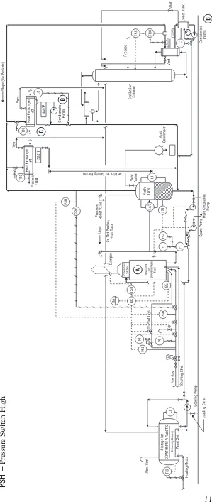
Figure 4 shows a liquid phase heating system employing DOWTHERM A fluid.
Advantages of Vapor
Phase Heating with
D
OWTHERMA Fluid
1. Vapor phase systems provide
much more heat per unit mass of heat medium passed through the user (Figures 2 and 3).
2. Vapor systems, with their
condens-ing vapor, provide a more uniform heat source and precision temperature control of the user. An equivalent liquid system would have to be operated at extreme flow rates in order to maintain the same close temperature uniformity. This is illustrated in Figures 2 and 3.
3. Vapor phase heating has an
advantage where it is difficult to control liquid flow pattern and velocity; e.g., in kettle jackets.
4. No pumps are needed when a
gravity return condensate system is used with a natural circulation vaporizer.
5. A vapor system requires less
work-ing inventory of DOWTHERM A fluid since the line to the user, and the user, are filled with vapor rather than liquid.
6. With heat-sensitive products,
where the maximum temperature of the heat transfer medium must be limited, heating may be accomplished more economically with condensing vapor than with liquid at high mass flow rates.
Figure 5 shows a vapor phase heating system employing DOWTHERM A fluid.
100 1000
1 10 100 1000
Film Coefficient, Btu/hr ft
2 °
F
Flow Rate, GPM 2
3
6 8
10
4
1"
2"
3"
6"
3/4
", 14 BWG
3/4
", 16 BWG
4"
1
1/2
"
1", 14 BWG
VELOCITY (ft/sec)
TUBE SIZE
1", 16 BWG
SCHEDULE 40 PIPE
1/2
", 16 BWG
1/2
", 18 BWG
0.4 0.5 0.6 0.7 0.8 0.9 1 1.1
100 200 300 400 500 600 700 800
Factor
Temperature, °F
W/(m2)(K)=[Btu/(hr)(ft2)(°F)](5.678)
Temperature Correction Multiplier Factor
Note: The values in this graph are based on the viscosity of fluid as supplied. Sieder and Tate Equation Process Heat Transfer,
D.Q. Kern (1950) p. 103
!
= 0.027 Re0.8PR1⁄3Nu
~
0.14 m
mw
Chart based on = 1
~
!
0.14 mmw
1 10 60
1 10 100
D
T for Liquid,
°
C
(kg/hr Liquid)/(kg/hr Vapor) 1
10 100
2 10 100
D
T for Liquid,
°
F
(lb/hr Liquid)/(lb/hr Vapor) Figure 2—Comparison of Liquid vs. Vapor Mass Flow Rates for DOWTHERM A Fluid at Various Liquid ∆ t’s
Basis: 600°F with 5°F Subcooling for Condensate of DOWTHERM A Fluid
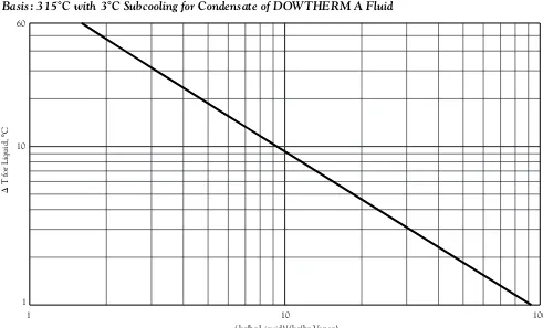
Figure 3 — Comparison of Liquid vs. Vapor Mass Flow Rates for DOWTHERM A Fluid at Various Liquid ∆ t’s
Basis: 315°C with 3°C Subcooling for Condensate of DOWTHERM A Fluid Figure 13 —Calculated Pressure vs. Enthalpy for DOWTHERM A Fluid (SI Units)
10 100 1000 3000
300
400
500
600
700
800
900
1000
1100
1200
Pressure, kPa
Enthalpy, kJ/kg
250°C
275°C
300°C
325°C
350°C
375°C
400°C
425°C
Density, kg/m
3
0.6 1.0
1.5
3.0
6.0 25.0
50.0 10.0
Entropy, kJ/kg K 2.7
2.8
2.9
3.0
3.1
3.2
3.3 3.4
3.5
3.6
3.7 3.8
3.9 Saturated Liquid
Instrument Legend BA – Burner Alarm BC – Burner Control BE –
Burner Element (Fire-Eye)
FI
–
Flow Indicator (Orifice)
FRC
–
Flow Recording Controller
FSL
–
Flow Switch Low
LA H / L – Level Alarm–High/Low LI – Level Indicator LC – Level Controller LSL –
Level Switch Low
PCV
–
Pressure Control Valve
PI
–
Pressure Indicator
PIC
–
Pressure Indicating Controller
PRV
–
Pressure Relief Valve
PSH
–
Pressure Switch High
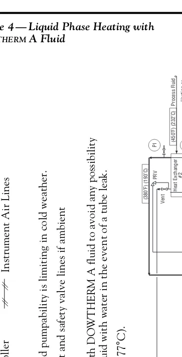
A
– External heating required if fluid pumpability is limiting in cold weather.
B
– Thermal tracing system on vent and safety valve lines if ambient temperature = <80
°
F (27
°
C).
C
– Heat exchanger #2 is cooled with D
O
W
THE
R
M
A fluid to avoid any possibility
of contaminating the process fluid with water in the event of a tube leak.
D
– Process fluid freezes at 350
°
F (177
°
C).
Figure 4 — Liquid Phase Heating with
DOWTHERM A Fluid
PSL
–
Pressure Switch Low
TIC
–
Temperature Indicating Controller
TRC
–
Temperature Recorder Controller
TSH
–
Temperature Switch High
▼ ▼ ▼ ▼ ▼ ▼ ▼ ▼ ▼ ▼ ▼ ▼ ▼ ▼ ▼ ▼ ▼ ▼ ▼ ▼ ▼ ▼ ▼ ▼ ▼ ▼ ▼ ▼▼ ▼ ▼ ▼ ▼ ▼ ▼ ▼ ▼ ▼ ▼ ▼ ▼ ▼ ▼ ▼ ▼ ▼ ▼ ▼ ▼ ▼ ▼ ▼ ▼ ▼ ▼ ▼ ▼ ▼ ▼ ▼ ▼ ▼ ▼ ▼ ▼ ▼ ▼ ▼ ▼ ▼ ▼ ▼ ▼ (450˚F) (232˚C) (380˚F) (193˚C) Heat Exchanger #2 Ven t (375˚F) (191˚C) PI TRC C D Steam Condensate LC Steam Condensate Pump TIC FI PIC LC Cooling Loop Cir culating Pump Steam Generator Process T an k Stm. Hdr . FI TIC TIC Jacket Loop Cir culating Pump Expansion Tan k PCV N
LA / LSL
Heating Loop Cir culating Pump Spare Pump Heater for DOWTHERM Fluid TIC 7 FRC FSL TSH Process Fluid BE BC BA 1 PSH PI
Slope Do Not Pocket, Heat T
race PSL PI To Pilot Light Heat Exchanger #1 Ven t TRC ▼ PCV Snuffing Stm. Fuel Gas Heating Media Atm. Ven t Storage T an k
and Panel Coil Cond.
TIC A B H L 2 Process Fluid ▼ ▼ ▼ PRV PRV Vent ▼ ▼ ▼ ▼
Pressure Relief Header Vent Header
Ven t Steam PRV LI ▼ ▼ ▼ Heating or Cooling Process Process Fluid ▼ PRV ▼ ▼ ▼ LI Loading Pump ▼ ▼
Principal Circuits with D
OWTHERM
Fluid
Electrical Lines Instrument Air Lines
Figure 12 —Calculated Pressure vs. Enthalpy for DOWTHERM A Fluid (English Units)
1 10 100 500
180 200 220 240 260 280 300 320 340 360 380 400 420 440 460 480 Pressure, psia Enthalpy Btu/lb
480°F
520°F
560°F
600°F
640°F
680°F
720°F
760°F
800°F
Density, lb/cu ft
0.02 0.04 0.07 0.1 0.2 0.4 0.7 1.0 1.5 2.0 3.0 Entropy, Btu/lb °F
Figure 5 — Vapor Phase Heating with
DOWTHERM A Fluid
Instrument Legend BA
–
Burner Alarm
BC
–
Burner Control
BE
–
Burner Element (Fire-Eye)
FI
–
Flow Indicator (Orifice)
FRC
–
Flow Recording Controller
FSL
–
Flow Switch Low
LA
H /
L
–
Level Alarm–High/Low
LI
–
Level Indicator
LC
–
Level Controller
LSL
–
Level Switch Low
PCV
–
Pressure Control Valve
PI
–
Pressure Indicator
PIC
–
Pressure Indicating Controller
PRV
–
Pressure Relief Valve
PSH
–
Pressure Switch High
PSL
–
Pressure Switch Low
TIC
–
Temperature Indicating Controller
TRC
–
Temperature Recorder Controller
TSH
–
Temperature Switch High
Principal Circuits with D
OWTHERM
Fluid
Electrical Lines Instrument Air Lines
Thermal Tracing System required if ambient temperature = <60
°
F (15
°
C).
A
–
Vaporizers for DOWTHERM A fluid utilize both natural and forced circulation.
B
–
A pump is required where there is insufficient elevation between vaporizer and heat user to return condensate by gravity.
C
–
Hand-throttled bypass required to prevent pump heat-up.
100 1000 10000 100000 1000000
50 100 150 200 250 300 350 400
Water Solubility, ppm (weight)
Temperature, °F
100 1000 10000 100000 1000000
0 50 100 150 200
Water Solubility, ppm (weight)
Temperature, °C
Whenever accidental or unusual conditions result in higher concen-trations of vapors or fumes, workers should wear respiratory protection suitable for organic mists and vapors. Where there is a possibility of oxygen deficiency, workers should use an air-supplied mask or positive pressure, self-contained breathing apparatus. In regular operations, concentrations of vapors in the atmosphere should be kept at levels that are not disagreeable. If ill effects occur from accidental exposure to heavy concentrations in the air, remove the victim to fresh air and get immediate medical attention.
Ingestion. Oral administration of DOWTHERM A heat transfer fluid
to laboratory rats has revealed a low order of systemic toxicity. The single-dose oral LD50 in female rats is 2487 mg/kg. Limited studies show no significant toxicity in rats that received daily oral doses, 5 days a week for 1 to 6 months, of 100 mg/kg DOWTHERM A fluid. Liver and
kidney effects were observed at higher doses.
Ingestion of small amounts of DOWTHERM A heat transfer fluid
incidental to handling should not cause injury. It should, however, be recognized that ill effects will result if substantial amounts are swallowed. Induce vomiting if large amounts of DOWTHERM A fluid are ingested.
Consult with medical personnel immediately.
Eye Contact. Contact with DOWTHERM A in both the liquid
and vapor form may be painful, but otherwise is only slightly irritating to the eyes and will not cause corneal injury. Whenever there is the potential for gross eye contamina-tion, face shields or chemical workers’ goggles should be worn to
avoid discomfort that might result from direct contact. Safety glasses are recommended for everyday use. If the eyes are accidentally contami-nated with fluid, they should be thoroughly washed with flowing water for 5 minutes and medical attention obtained if there is any evidence of irritation.
If the fluid is contaminated with material being processed or with other materials, additional treatment may be required.
Skin Contact. Single exposures to DOWTHERM A in liquid form are
not irritating to the skin. However, prolonged or repeated skin contact may cause irritation and should therefore be avoided. Fluid that has been used at high temperatures for extended periods of time can cause skin irritation or dermatitis.
The product is not likely to be absorbed in toxic amounts.
Contaminated skin should be immediately and thoroughly washed with soap and water. Contaminated clothing and shoes should be removed at once and the clothing decontaminated before reuse.
H
EALTH ANDE
NVIRONMENTALC
ONSIDERATIONSA Material Safety Data Sheet (MSDS) for DOWTHERM A heat transfer fluid is available by calling the number listed on the back of this brochure. The MSDS contains com-plete health and safety information regarding the use of this product. Read and understand the MSDS before handling or otherwise using this product.
Health Considerations
Inhalation. Animal studies indicate that DOWTHERM A fluid has a low order of inhalation toxicity. Limited studies in rats, rabbits, and guinea pigs did not show significant effects from exposures of 7–10 ppm, 7 hours a day, 5 days a week for 6 months. These were the highest vapor con-centrations that could be maintained without condensation and fogging.
DOWTHERM A fluid has a striking odor that becomes quite disagreeable, even irritating to the eyes and nose, at concentrations far below 7 ppm. This odor serves as a warning to prevent excessive exposure to vapors and fumes. The OSHA standard for this mixture is 1 ppm. The ACGIH TLV is 1 ppm TWA, 2 ppm STEL for the diphenyl oxide component and 0.2 ppm TWA for the biphenyl component.
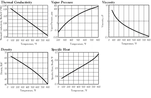
Figure 9 — Liquid Properties of DOWTHERM A Liquid (SI Units) Figure 8—Liquid Properties of DOWTHERM A Liquid (English Units)
0.07 0.09 0.11 0.13 0.14
0 100 200 300 400
Thermal Conductivity, W/mK
Temperature, °C
0.01 0.1 1 10 20
150 200 250 300 350 400
Vapor Pressure, bar
Temperature, °C
0.1 1 10
0 50 100 150 200 250 300 350 400
Viscosity, mPa sec
Temperature, °C
600 700 800 900 1000 1100
0 100 200 300 400
Density, kg/m
3
Temperature, °C
1.5 1.9 2.3 2.7 2.9
0 100 200 300 400
Specific Heat, kJ/kg K
Temperature, °C
0.04 0.05 0.06 0.07 0.08 0.085
0 100 200 300 400 500 600 700 800
Thermal Conductivity, Btu/hr ft
2 (°
F/ft)
Temperature, °F
0.01 0.1 1 10 100 300
200 300 400 500 600 700 800
Vapor Pressure, psia
Temperature, °F
0.1 1 10
0 100 200 300 400 500 600 700 800
Viscosity, cP
Temperature, °F
40 45 50 55 60 65 70
0 100 200 300 400 500 600 700 800
Density, lb/ft
3
Temperature, °F
0.3 0.4 0.5 0.6 0.7
0 100 200 300 400 500 600 700 800
Specific Heat, Btu/lb
°
F
Temperature, °F
Thermal Conductivity Vapor Pressure Viscosity
Density Specific Heat
Thermal Conductivity Vapor Pressure Viscosity
Data indicate that a large percentage of the medium present in water will be stripped out during aeration in the primary stage of a waste treatment facility.
Bioconcentration. Dow studies have shown that both components of DOWTHERM A fluid—biphenyl and
diphenyl oxide—bioconcentrate in trout, but that when these trout are exposed to fresh water, the compounds disappear from their tissues in a relatively short time.
Should this material be discharged into a body of water, it may biocon-centrate in fish, but at a significantly lower level than compounds such as polychlorinated biphenyl. Further-more, because of the speed with which the material is cleared from the tissues and biodegrades, it is unlikely to pose a serious problem.
Environmental
Considerations
Stability.DOWTHERM A fluid has a 5-day BOD of 1.70 parts/part, 62% of its theoretical oxygen demand. Its
COD is 2.53 parts/part. This indicates that it is biodegradable and non-persistent in the environment. There is no evidence that harmful products are formed as a result of biodegradation. Once its bacteria are acclimated, a waste treatment system should achieve a high degree of removal of fluid before the waste-water effluent reaches the receiving body of water.
Movement. The water solubility of this material is very low—only 14 ppm at ambient temperatures—and if amounts exceeding this limit are mixed with water, the medium will settle to the bottom. Of course, turbulence and the presence of other materials may affect the physical condition of the solution. It is also possible that an emulsion may form under certain conditions.
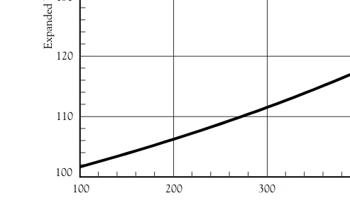
Figure 6 — Expansion of DOWTHERM A Liquid
(Basis: 100 Gallons at 60°F)
Figure 7— Expansion of DOWTHERM A Liquid
(Basis: 1 m3 at 25°C)
100 110 120 130 140 150 160
100 200 300 400 500 600 700 800
Expanded Volume, gal.
Temperature, °F
1 1.1 1.2 1.3 1.4 1.5 1.6
50 100 150 200 250 300 350 400
Expanded Volume, m
3
the shipping container. Cooling the sample below 100°F (40°C) will prevent the possibility of thermal burns to personnel; also, the fluid is then below its flash point. In addition, any low boilers will not flash and be lost from the sample. Cooling can be done by either a batch or continuous process. The batch method consists of isolating the hot sample of fluid from the system in a properly designed sample collector and then cooling it to below 100°F (40°C). After it is cooled, it can be withdrawn from the sampling collector into a container for shipment.
The continuous method consists of controlling the fluid at a very low rate through a steel or stainless steel cooling coil so as to maintain it at 100°F (40°C) or lower as it comes out of the end of the cooler into the sample collector. Before a sample is taken, the sampler should be thor-oughly flushed. This initial fluid should be returned to the system or disposed of in a safe manner in com-pliance with all laws and regulations.
It is important that samples sent for analysis be representative of the charge in the unit. Ordinarily, samples should be taken from the main circulating line of a liquid system. Occasionally, additional samples may have to be taken from other parts of the system where specific problems exist. A detailed method for analyzing the fluid to determine its quality is available upon request.
Used heat transfer fluid which has been stored in drums or tanks should be sampled in such a fashion as to ensure a representative sample.
C
USTOMERS
ERVICEFORU
SERSOFD
OWTHERM
A
H
EATT
RANSFERF
LUIDFluid Analysis
The Dow Chemical Company offers an analytical service for DOWTHERM A heat transfer fluid.
It is recommended that users send a one-pint (0.5 liter) representative sample at least annually to:
North America & Pacific
The Dow Chemical Company Larkin Lab/Thermal Fluids 1691 North Swede Road Midland, Michigan 48674 United States of America
Europe
Dow Benelux NV
SYLTHERM† and DOWTHERM
Testing Laboratory Oude Maasweg 4
3197 KJ Rotterdam – Botlek The Netherlands
Latin America
Dow Quimica S.A. Fluid Analysis Service 1671, Alexandre Dumas Santo Amaro – Sao Paulo – Brazil 04717-903
This analysis gives a profile of fluid changes to help identify trouble from product contamination or thermal decomposition.
When a sample is taken from a hot system, it should be cooled to below 100°F (40°C) before it is put into
Fluid Return Program
for D
OWTHERMFluids
In the unlikely event that you need to change out DOWTHERM A fluid,
Dow offers a fluid return program. If analysis of a particular fluid sample reveals significant thermal degradation of the medium, the customer will be advised to return the fluid in his system to Dow. If the fluid is contaminated with organic materials of low thermal stability, it may not be acceptable for Dow processing and will not qualify for the return program. In this case, Dow will advise the customer that the fluid cannot be processed and therefore should not be returned to Dow. No material should be sent to Dow until the fluid analysis has been completed and the customer informed of the results.
If the analysis shows fluid change-out is necessary, the customer should order sufficient new material to recharge the system before sending the old fluid to Dow. Under the fluid return program, Dow will credit the customer for all usable material recovered.
The Dow fluid return program per-mits customers to minimize their heat transfer fluid investment, handling downtime and inventory, while assuring that replacement fluid is of the highest quality.
Before returning material for credit, contact Dow at the number for your area listed on the back of this bulletin for details.
For further information, please contact your nearest Dow repre-sentative or call the number for your area listed on the back of this brochure. Ask for DOWTHERM A Fluid.
†Trademark of Dow Corning Corporation
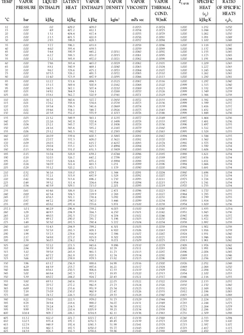
Table 5 — Saturated Vapor Properties of DOWTHERM A Fluid (SI Units)
TEMP VAPOR LIQUID LATENT VAPOR VAPOR VAPOR VAPOR ZVAPOR SPECIFIC RATIO PRESSURE ENTHALPY HEAT ENTHALPY DENSITY VISCOSITY THERMAL HEAT OF SPECIFIC
COND. (cp) HEATS
°C bar kJ/kg kJ/kg kJ/kg kg/m3 mPa sec W/mK kJ/kg K c
p/cv
12 0.00 0.0 409.0 409.0 0.0053 0.0074 1.000 1.032 1.050
15 0.00 4.9 407.2 412.1 0.0054 0.0075 1.000 1.044 1.050
20 0.00 13.1 404.4 417.4 0.0055 0.0078 1.000 1.062 1.050
25 0.00 21.3 401.5 422.8 0.0056 0.0081 1.000 1.081 1.049
30 0.00 29.5 398.8 428.3 0.0057 0.0084 1.000 1.100 1.048
35 0.00 37.7 396.1 433.8 0.0058 0.0086 1.000 1.118 1.047
40 0.00 46.0 393.4 439.5 0.0059 0.0089 1.000 1.137 1.046
45 0.00 54.4 390.9 445.2 0.0011 0.0060 0.0092 1.000 1.155 1.045
50 0.00 62.7 388.3 451.0 0.0015 0.0061 0.0095 1.000 1.173 1.045
55 0.00 71.2 385.8 457.0 0.0021 0.0062 0.0098 1.000 1.191 1.044
60 0.00 79.6 383.4 463.0 0.0029 0.0062 0.0101 1.000 1.209 1.043
65 0.00 88.1 380.9 469.1 0.0040 0.0063 0.0104 1.000 1.227 1.043
70 0.00 96.7 378.6 475.2 0.0053 0.0064 0.0107 1.000 1.245 1.042
75 0.00 105.3 376.2 481.5 0.0072 0.0065 0.0110 1.000 1.262 1.041
80 0.00 114.0 373.9 487.9 0.0095 0.0066 0.0113 1.000 1.280 1.041
85 0.00 122.7 371.6 494.3 0.0125 0.0067 0.0116 1.000 1.297 1.040
90 0.00 131.5 369.4 500.8 0.0162 0.0068 0.0120 0.999 1.315 1.040
95 0.00 140.3 367.1 507.4 0.0210 0.0069 0.0123 0.999 1.332 1.039
100 0.01 149.2 364.9 514.1 0.0268 0.0070 0.0126 0.999 1.349 1.039
105 0.01 158.1 362.7 520.9 0.0341 0.0071 0.0129 0.999 1.366 1.038
110 0.01 167.1 360.6 527.7 0.0430 0.0072 0.0133 0.999 1.382 1.038
115 0.01 176.2 358.4 534.6 0.0538 0.0073 0.0136 0.999 1.399 1.037
120 0.01 185.4 356.3 541.6 0.0669 0.0074 0.0139 0.998 1.416 1.037
125 0.02 194.6 354.1 548.7 0.0826 0.0075 0.0143 0.998 1.432 1.037
130 0.02 203.8 352.0 555.9 0.1013 0.0076 0.0146 0.998 1.448 1.036
135 0.03 213.2 349.9 563.1 0.1235 0.0077 0.0149 0.997 1.464 1.036
140 0.03 222.6 347.8 570.4 0.1498 0.0078 0.0153 0.997 1.481 1.036
145 0.04 232.1 345.7 577.8 0.1806 0.0078 0.0156 0.996 1.497 1.035
150 0.05 241.6 343.6 585.2 0.2165 0.0079 0.0160 0.995 1.512 1.035
155 0.06 251.2 341.5 592.7 0.2583 0.0080 0.0163 0.995 1.528 1.035
160 0.07 260.9 339.4 600.3 0.3065 0.0081 0.0167 0.994 1.544 1.035
165 0.08 270.7 337.3 608.0 0.3621 0.0082 0.0170 0.993 1.560 1.035
170 0.09 280.5 335.2 615.7 0.4257 0.0083 0.0174 0.992 1.575 1.034
175 0.11 290.4 333.1 623.5 0.4984 0.0084 0.0178 0.991 1.590 1.034
180 0.13 300.4 331.0 631.3 0.5809 0.0085 0.0181 0.990 1.606 1.034
185 0.15 310.4 328.8 639.2 0.6744 0.0086 0.0185 0.988 1.621 1.034
190 0.18 320.5 326.7 647.2 0.7798 0.0087 0.0189 0.987 1.636 1.034
195 0.21 330.7 324.6 655.2 0.8984 0.0088 0.0192 0.985 1.651 1.034
200 0.24 340.9 322.4 663.3 1.031 0.0089 0.0196 0.984 1.666 1.034
205 0.28 351.2 320.2 671.5 1.179 0.0090 0.0200 0.982 1.681 1.034
210 0.32 361.6 318.0 679.7 1.344 0.0091 0.0204 0.980 1.696 1.034
215 0.37 372.1 315.8 687.9 1.528 0.0092 0.0207 0.978 1.711 1.034
220 0.42 382.6 313.6 696.2 1.730 0.0093 0.0211 0.975 1.726 1.034
225 0.48 393.2 311.4 704.6 1.954 0.0094 0.0215 0.973 1.741 1.034
230 0.54 403.9 309.1 713.0 2.201 0.0095 0.0219 0.970 1.755 1.034
235 0.61 414.6 306.8 721.4 2.471 0.0096 0.0223 0.967 1.770 1.035
240 0.69 425.4 304.5 729.9 2.768 0.0097 0.0227 0.964 1.785 1.035
245 0.77 436.3 302.1 738.4 3.092 0.0098 0.0231 0.961 1.799 1.035
250 0.87 447.2 299.8 747.0 3.446 0.0099 0.0234 0.958 1.814 1.036
255 0.97 458.2 297.4 755.6 3.831 0.0100 0.0238 0.954 1.829 1.036
257.1 1.01 462.9 296.4 759.2 4.003 0.0100 0.0240 0.953 1.835 1.036
260 1.08 469.3 294.9 764.3 4.250 0.0101 0.0242 0.951 1.843 1.036
265 1.20 480.5 292.5 773.0 4.704 0.0102 0.0246 0.947 1.858 1.037
270 1.33 491.7 290.0 781.7 5.196 0.0103 0.0250 0.942 1.872 1.037
275 1.48 503.0 287.5 790.4 5.727 0.0104 0.0254 0.938 1.887 1.038
280 1.63 514.3 284.9 799.2 6.301 0.0105 0.0258 0.934 1.902 1.038
285 1.80 525.8 282.3 808.1 6.920 0.0106 0.0263 0.929 1.916 1.039
290 1.98 537.3 279.6 816.9 7.586 0.0107 0.0267 0.924 1.931 1.040
295 2.17 548.8 277.0 825.8 8.302 0.0108 0.0271 0.919 1.946 1.041
300 2.38 560.5 274.2 834.7 9.071 0.0109 0.0275 0.913 1.961 1.042
305 2.60 572.2 271.5 843.6 9.896 0.0110 0.0279 0.908 1.976 1.042
310 2.84 583.9 268.6 852.6 10.78 0.0111 0.0283 0.902 1.991 1.044
315 3.10 595.8 265.8 861.5 11.73 0.0113 0.0287 0.896 2.006 1.045
320 3.37 607.7 262.8 870.5 12.74 0.0114 0.0292 0.889 2.021 1.046
325 3.66 619.7 259.8 879.5 13.82 0.0115 0.0296 0.883 2.036 1.047
330 3.96 631.7 256.8 888.6 14.98 0.0116 0.0300 0.876 2.052 1.048
335 4.29 643.9 253.7 897.6 16.21 0.0117 0.0304 0.869 2.068 1.050
340 4.64 656.1 250.5 906.6 17.53 0.0119 0.0309 0.862 2.084 1.052
345 5.00 668.4 247.3 915.7 18.93 0.0120 0.0313 0.854 2.100 1.053
350 5.39 680.7 244.0 924.7 20.43 0.0121 0.0317 0.846 2.116 1.055
355 5.80 693.1 240.6 933.8 22.03 0.0122 0.0322 0.838 2.133 1.057
360 6.24 705.7 237.2 942.8 23.73 0.0124 0.0326 0.830 2.150 1.060
365 6.69 718.2 233.6 951.9 25.54 0.0125 0.0331 0.821 2.168 1.062
370 7.18 730.9 230.0 960.9 27.47 0.0126 0.0335 0.812 2.186 1.065
375 7.68 743.7 226.3 970.0 29.53 0.0128 0.0340 0.803 2.204 1.068
380 8.22 756.5 222.5 979.0 31.73 0.0129 0.0344 0.793 2.224 1.071
385 8.78 769.4 218.6 988.0 34.07 0.0131 0.0349 0.783 2.244 1.075
390 9.37 782.4 214.5 997.0 36.58 0.0132 0.0354 0.773 2.264 1.079
395 9.99 795.5 210.4 1005.9 39.25 0.0134 0.0358 0.762 2.286 1.083
400 10.64 808.7 206.1 1014.8 42.11 0.0136 0.0363 0.751 2.309 1.088
405 11.32 822.0 201.7 1023.7 45.17 0.0138 0.0368 0.740 2.333 1.094
410 12.03 835.4 197.1 1032.5 48.45 0.0139 0.0373 0.728 2.359 1.100
415 12.78 848.9 192.4 1041.3 51.98 0.0141 0.0378 0.715 2.387 1.107
420 13.56 862.5 187.5 1050.0 55.77 0.0143 0.0383 0.703 2.417 1.115
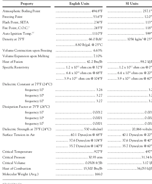
Table 1 — Physical Properties of DOWTHERM A Fluid
(Laboratory values not to be confused with, or substitutes for, specifications). None of below are specifications.
Property English Units SI Units
Atmospheric Boiling Point ... 494.8°F ... 257.1°C
Freezing Point ... 53.6°F ... 12.0°C
Flash Point, SETA ... 236°F ... 113°C
Fire Point, C.O.C.† ... 245°F ... 118°C
Auto Ignition Temp.†† ... 1110°F ... 599°C
Density at 75°F ... 66.0 lb/ft3 ... 1056 kg/m3 @ 25°C
... 8.80 lb/gal. @ 25°C
Volume Contraction upon Freezing ... 6.63%
Volume Expansion upon Melting ... 7.10%
Heat of Fusion ... 42.2 Btu/lb ... 98.2 kJ/kg
Specific Resistivity ... 1.2 x 10¹² ohm cm @ 32°F ... 1.2 x 10¹² ohm cm @ 0°C
... 6.4 x 10¹¹ ohm cm @ 68°F ... 6.4 x 10¹¹ ohm cm @ 20°C
... 3.9 x 10¹¹ ohm cm @ 104°F ... 3.9 x 10¹¹ ohm cm @ 40°C
Dielectric Constant at 75°F (24°C)
frequency 103 ... 3.26 ... 3.26
frequency 104 ... 3.27 ... 3.27
frequency 105 ... 3.27 ... 3.27
Dissipation Factor at 75°F (24°C)
frequency 103 ... 0.0012 ... 0.0012
frequency 104 ... 0.0001 ... 0.0001
frequency 105 ... 0.0001 ... 0.0001
Dielectric Strength at 75°F (24°C) ... 530 volts/mil ... 20,866 volts/nm
Surface Tension in Air ...40.1 Dynes/cm @ 68°F ... 40.1 Dynes/cm @ 20°C
... 37.6 Dynes/cm @ 104°F ... 37.6 Dynes/cm @ 40°C
... 35.7 Dynes/cm @ 140°F ... 35.7 Dynes/cm @ 60°C
Critical Temperature ... 927°F ... 497°C
Critical Pressure ... 30.93 atm ... 31.34 bar
Critical Volume ... 0.0508 ft3/lb ... 3.17 l/kg
Heat of Combustion ... 15,500 Btu/lb ... 36,053 kJ/kg
Molecular Weight (Avg.) ... 166.0
†Cleveland Open Cup ††ASTM E659-78
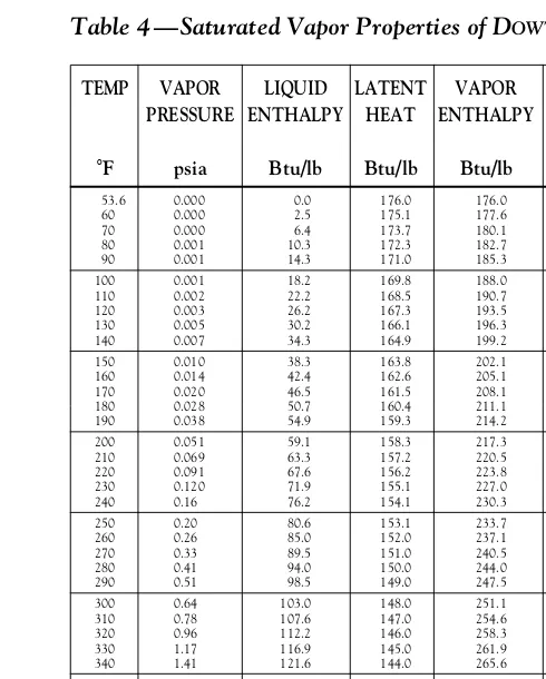
Table 4 —Saturated Vapor Properties of DOWTHERM A Fluid (English Units)
TEMP VAPOR LIQUID LATENT VAPOR VAPOR VAPOR VAPOR ZVAPOR SPECIFIC RATIO PRESSURE ENTHALPY HEAT ENTHALPY DENSITY VISCOSITY THERMAL HEAT OF SPECIFIC
COND. (cp) HEATS
°F psia Btu/lb Btu/lb Btu/lb lb/ft3 cP Btu/hr ft2(°F/ft) Btu/lb °F c
p/cv
53.6 0.000 0.0 176.0 176.0 0.0053 0.0043 1.000 0.247 1.051
60 0.000 2.5 175.1 177.6 0.0054 0.0044 1.000 0.250 1.050
70 0.000 6.4 173.7 180.1 0.0055 0.0046 1.000 0.255 1.049
80 0.001 10.3 172.3 182.7 0.0056 0.0047 1.000 0.260 1.048
90 0.001 14.3 171.0 185.3 0.0057 0.0049 1.000 0.265 1.047
100 0.001 18.2 169.8 188.0 0.0058 0.0051 1.000 0.270 1.047
110 0.002 22.2 168.5 190.7 0.0059 0.0053 1.000 0.275 1.046
120 0.003 26.2 167.3 193.5 0.0060 0.0055 1.000 0.279 1.045
130 0.005 30.2 166.1 196.3 0.0001 0.0061 0.0056 1.000 0.284 1.044
140 0.007 34.3 164.9 199.2 0.0002 0.0062 0.0058 1.000 0.289 1.043
150 0.010 38.3 163.8 202.1 0.0003 0.0064 0.0060 1.000 0.294 1.043
160 0.014 42.4 162.6 205.1 0.0004 0.0065 0.0062 1.000 0.298 1.042
170 0.020 46.5 161.5 208.1 0.0005 0.0066 0.0064 1.000 0.303 1.041
180 0.028 50.7 160.4 211.1 0.0007 0.0067 0.0066 1.000 0.308 1.041
190 0.038 54.9 159.3 214.2 0.0009 0.0068 0.0068 1.000 0.312 1.040
200 0.051 59.1 158.3 217.3 0.0012 0.0069 0.0070 0.999 0.317 1.039
210 0.069 63.3 157.2 220.5 0.0016 0.0070 0.0072 0.999 0.321 1.039
220 0.091 67.6 156.2 223.8 0.0021 0.0071 0.0075 0.999 0.326 1.038
230 0.120 71.9 155.1 227.0 0.0027 0.0072 0.0077 0.999 0.330 1.038
240 0.16 76.2 154.1 230.3 0.0034 0.0073 0.0079 0.999 0.335 1.037
250 0.20 80.6 153.1 233.7 0.0044 0.0074 0.0081 0.998 0.339 1.037
260 0.26 85.0 152.0 237.1 0.0055 0.0075 0.0083 0.998 0.344 1.037
270 0.33 89.5 151.0 240.5 0.0069 0.0076 0.0085 0.997 0.348 1.036
280 0.41 94.0 150.0 244.0 0.0086 0.0077 0.0087 0.997 0.352 1.036
290 0.51 98.5 149.0 247.5 0.0106 0.0078 0.0090 0.996 0.356 1.036
300 0.64 103.0 148.0 251.1 0.0130 0.0079 0.0092 0.996 0.361 1.035
310 0.78 107.6 147.0 254.6 0.0158 0.0080 0.0094 0.995 0.365 1.035
320 0.96 112.2 146.0 258.3 0.0191 0.0081 0.0097 0.994 0.369 1.035
330 1.17 116.9 145.0 261.9 0.0230 0.0082 0.0099 0.993 0.373 1.035
340 1.41 121.6 144.0 265.6 0.0275 0.0083 0.0101 0.992 0.377 1.034
350 1.70 126.4 143.0 269.3 0.0328 0.0084 0.0103 0.990 0.381 1.034
360 2.03 131.1 142.0 273.1 0.0388 0.0086 0.0106 0.989 0.385 1.034
370 2.42 135.9 141.0 276.9 0.0457 0.0087 0.0108 0.988 0.389 1.034
380 2.87 140.8 139.9 280.7 0.0535 0.0088 0.0111 0.986 0.393 1.034
390 3.38 145.7 138.9 284.6 0.0624 0.0089 0.0113 0.984 0.397 1.034
400 3.96 150.6 137.9 288.5 0.0725 0.0090 0.0115 0.982 0.401 1.034
410 4.63 155.6 136.8 292.4 0.0839 0.0091 0.0118 0.980 0.405 1.034
420 5.38 160.6 135.8 296.3 0.0967 0.0092 0.0120 0.977 0.409 1.034
430 6.23 165.6 134.7 300.3 0.1110 0.0093 0.0123 0.975 0.413 1.034
440 7.19 170.7 133.6 304.3 0.1270 0.0094 0.0125 0.972 0.417 1.034
450 8.25 175.8 132.5 308.3 0.1447 0.0095 0.0128 0.969 0.421 1.035
460 9.45 180.9 131.4 312.4 0.1644 0.0096 0.0130 0.966 0.425 1.035
470 10.78 186.1 130.3 316.4 0.1861 0.0097 0.0133 0.962 0.429 1.035
480 12.25 191.4 129.2 320.5 0.2100 0.0098 0.0135 0.959 0.433 1.035
490 13.87 196.6 128.0 324.7 0.2364 0.0100 0.0138 0.955 0.437 1.036
494.8 14.71 199.1 127.5 326.6 0.2499 0.0100 0.0139 0.953 0.438 1.036
500 15.66 201.9 126.9 328.8 0.2653 0.0101 0.0140 0.951 0.441 1.036
510 17.63 207.2 125.7 332.9 0.2969 0.0102 0.0143 0.946 0.444 1.037
520 19.79 212.6 124.5 337.1 0.3315 0.0103 0.0145 0.942 0.448 1.037
530 22.15 218.0 123.3 341.3 0.3692 0.0104 0.0148 0.937 0.452 1.038
540 24.72 223.5 122.1 345.5 0.4102 0.0105 0.0150 0.932 0.456 1.039
550 27.51 228.9 120.8 349.7 0.4547 0.0107 0.0153 0.926 0.460 1.040
560 30.54 234.5 119.5 354.0 0.5030 0.0108 0.0156 0.920 0.464 1.040
570 33.83 240.0 118.2 358.2 0.5554 0.0109 0.0158 0.914 0.468 1.041
580 37.37 245.6 116.9 362.5 0.6119 0.0110 0.0161 0.908 0.472 1.042
590 41.20 251.2 115.6 366.8 0.6730 0.0111 0.0164 0.902 0.476 1.044
600 45.31 256.9 114.2 371.1 0.7389 0.0113 0.0166 0.895 0.480 1.045
610 49.73 262.6 112.8 375.4 0.8099 0.0114 0.0169 0.888 0.484 1.046
620 54.47 268.3 111.4 379.7 0.8864 0.0115 0.0172 0.880 0.488 1.048
630 59.53 274.1 109.9 384.0 0.9686 0.0117 0.0175 0.873 0.492 1.049
640 64.95 279.9 108.4 388.3 1.057 0.0118 0.0177 0.865 0.496 1.051
650 70.73 285.8 106.9 392.6 1.152 0.0119 0.0180 0.857 0.501 1.053
660 76.89 291.7 105.3 397.0 1.254 0.0121 0.0183 0.848 0.505 1.055
670 83.44 297.6 103.7 401.3 1.364 0.0122 0.0186 0.839 0.509 1.057
680 90.40 303.6 102.0 405.6 1.481 0.0124 0.0189 0.830 0.514 1.060
690 97.79 309.6 100.3 409.9 1.608 0.0125 0.0191 0.820 0.519 1.062
700 105.6 315.7 98.6 414.3 1.743 0.0127 0.0194 0.810 0.523 1.066
710 113.9 321.8 96.8 418.6 1.888 0.0128 0.0197 0.799 0.528 1.069
720 122.7 327.9 95.0 422.9 2.045 0.0130 0.0200 0.789 0.534 1.073
730 131.9 334.1 93.1 427.2 2.213 0.0132 0.0203 0.777 0.539 1.077
740 141.7 340.4 91.1 431.5 2.394 0.0134 0.0206 0.766 0.545 1.082
750 152.0 346.7 89.1 435.7 2.588 0.0135 0.0209 0.754 0.551 1.087
760 162.9 353.0 87.0 440.0 2.798 0.0137 0.0212 0.741 0.557 1.093
770 174.4 359.4 84.8 444.2 3.025 0.0139 0.0215 0.728 0.564 1.100
780 186.4 365.9 82.5 448.4 3.270 0.0142 0.0219 0.714 0.571 1.108
790 199.1 372.4 80.2 452.5 3.537 0.0144 0.0222 0.700 0.579 1.117
TEMP VAPOR VISCOSITY SPECIFIC THERMAL DENSITY
PRESS. HEAT COND.
°F psia cP Btu/lb °F Btu/hr ft2(°F/ft) lb/ft3
53.6 0.000 5.52 0.370 0.0809 66.54 60 0.000 4.91 0.373 0.0805 66.37 70 0.000 4.15 0.377 0.0800 66.10 80 0.001 3.55 0.380 0.0795 65.82 90 0.001 3.07 0.384 0.0790 65.55
100 0.001 2.69 0.388 0.0785 65.28 110 0.002 2.38 0.392 0.0780 65.00 120 0.003 2.12 0.396 0.0775 64.72 130 0.005 1.90 0.399 0.0769 64.44 140 0.007 1.72 0.403 0.0764 64.16
150 0.010 1.57 0.407 0.0759 63.88 160 0.014 1.43 0.411 0.0754 63.60 170 0.020 1.32 0.414 0.0749 63.32 180 0.028 1.22 0.418 0.0744 63.03 190 0.038 1.13 0.422 0.0739 62.75
200 0.051 1.05 0.426 0.0733 62.46 210 0.069 0.98 0.429 0.0728 62.17 220 0.091 0.92 0.433 0.0723 61.88 230 0.120 0.86 0.437 0.0718 61.59 240 0.16 0.81 0.441 0.0713 61.30
250 0.20 0.76 0.444 0.0708 61.00 260 0.26 0.72 0.448 0.0703 60.71 270 0.33 0.68 0.452 0.0698 60.41 280 0.41 0.65 0.456 0.0692 60.11 290 0.51 0.62 0.459 0.0687 59.81
300 0.64 0.59 0.463 0.0682 59.51 310 0.78 0.56 0.467 0.0677 59.20 320 0.96 0.53 0.470 0.0672 58.90 330 1.17 0.51 0.474 0.0667 58.59 340 1.41 0.49 0.478 0.0662 58.28
350 1.70 0.47 0.481 0.0656 57.97 360 2.03 0.45 0.485 0.0651 57.65 370 2.42 0.43 0.489 0.0646 57.34 380 2.87 0.41 0.492 0.0641 57.02 390 3.38 0.40 0.496 0.0636 56.70
400 3.96 0.38 0.500 0.0631 56.37 410 4.63 0.37 0.503 0.0626 56.05 420 5.38 0.35 0.507 0.0620 55.72 430 6.23 0.34 0.511 0.0615 55.39
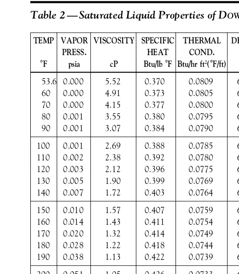
Table 2 — Saturated Liquid Properties of DOWTHERM A Fluid (English Units)
TEMP VAPOR VISCOSITY SPECIFIC THERMAL DENSITY
PRESS. HEAT COND.
°F psia cP Btu/lb °F Btu/hr ft2(°F/ft) lb/ft3
440 7.19 0.33 0.515 0.0610 55.06 450 8.25 0.32 0.518 0.0605 54.72 460 9.45 0.30 0.522 0.0600 54.38 470 10.78 0.29 0.526 0.0595 54.04 480 12.25 0.28 0.529 0.0590 53.70
490 13.87 0.27 0.533 0.0585 53.35 494.8 14.71 0.27 0.535 0.0582 53.18 500 15.66 0.27 0.537 0.0579 53.00 510 17.63 0.26 0.540 0.0574 52.65 520 19.79 0.25 0.544 0.0569 52.29
530 22.15 0.24 0.548 0.0564 51.93 540 24.72 0.23 0.552 0.0559 51.57 550 27.51 0.23 0.555 0.0554 51.20 560 30.54 0.22 0.559 0.0549 50.82 570 33.83 0.21 0.563 0.0543 50.45
580 37.37 0.21 0.567 0.0538 50.07 590 41.20 0.20 0.571 0.0533 49.68 600 45.31 0.19 0.575 0.0528 49.29 610 49.73 0.19 0.579 0.0523 48.89 620 54.47 0.18 0.583 0.0518 48.49
630 59.53 0.18 0.587 0.0513 48.08 640 64.95 0.17 0.591 0.0508 47.67 650 70.73 0.17 0.595 0.0502 47.25 660 76.89 0.16 0.599 0.0497 46.82 670 83.44 0.16 0.604 0.0492 46.39
680 90.40 0.15 0.608 0.0487 45.94 690 97.79 0.15 0.613 0.0482 45.49 700 105.6 0.14 0.617 0.0477 45.03 710 113.9 0.14 0.622 0.0472 44.56 720 122.7 0.14 0.627 0.0466 44.08
730 131.9 0.13 0.633 0.0461 43.59 740 141.7 0.13 0.638 0.0456 43.09 750 152.0 0.13 0.644 0.0451 42.57 760 162.9 0.12 0.651 0.0446 42.04 770 174.4 0.12 0.658 0.0441 41.49
780 186.4 0.12 0.665 0.0436 40.93 790 199.1 0.11 0.673 0.0430 40.34 800 212.5 0.11 0.682 0.0425 39.74
TEMP VAPOR VISCOSITY SPECIFIC THERMAL DENSITY
PRESS. HEAT COND.
°C bar mPa sec kJ/kg K W/mK kg/m3
12 0.00 5.52 1.550 0.1400 1065.9 15 0.00 5.00 1.558 0.1395 1063.5 20 0.00 4.29 1.573 0.1387 1059.6 25 0.00 3.71 1.587 0.1379 1055.7
30 0.00 3.25 1.601 0.1371 1051.7 35 0.00 2.87 1.616 0.1363 1047.8 40 0.00 2.56 1.630 0.1355 1043.8 45 0.00 2.30 1.644 0.1347 1039.8
50 0.00 2.07 1.658 0.1339 1035.8 55 0.00 1.88 1.673 0.1331 1031.8 60 0.00 1.72 1.687 0.1323 1027.8 65 0.00 1.58 1.701 0.1315 1023.7
70 0.00 1.46 1.715 0.1307 1019.7 75 0.00 1.35 1.729 0.1299 1015.6 80 0.00 1.25 1.744 0.1291 1011.5 85 0.00 1.17 1.758 0.1283 1007.4
90 0.00 1.09 1.772 0.1275 1003.2 95 0.00 1.03 1.786 0.1267 999.1 100 0.01 0.97 1.800 0.1259 994.9 105 0.01 0.91 1.814 0.1251 990.7
110 0.01 0.86 1.828 0.1243 986.5 115 0.01 0.82 1.842 0.1235 982.3 120 0.01 0.77 1.856 0.1227 978.1 125 0.02 0.73 1.870 0.1219 973.8
130 0.02 0.70 1.884 0.1211 969.5 135 0.03 0.67 1.898 0.1203 965.2 140 0.03 0.64 1.912 0.1195 960.9 145 0.04 0.61 1.926 0.1187 956.6
150 0.05 0.58 1.940 0.1179 952.2 155 0.06 0.56 1.954 0.1171 947.8 160 0.07 0.53 1.968 0.1163 943.4 165 0.08 0.51 1.982 0.1155 938.9
170 0.09 0.49 1.996 0.1147 934.5 175 0.11 0.47 2.010 0.1139 930.0 180 0.13 0.46 2.023 0.1131 925.5 185 0.15 0.44 2.037 0.1123 920.9
190 0.18 0.42 2.051 0.1115 916.4 195 0.21 0.41 2.065 0.1107 911.8 200 0.24 0.39 2.079 0.1099 907.1 205 0.28 0.38 2.093 0.1091 902.5
210 0.32 0.37 2.107 0.1083 897.8 215 0.37 0.35 2.120 0.1075 893.1 220 0.42 0.34 2.134 0.1067 888.3
Table 3 — Saturated Liquid Properties of DOWTHERM A Fluid (SI Units)
TEMP VAPOR VISCOSITY SPECIFIC THERMAL DENSITY
PRESS. HEAT COND.
°C bar mPa sec kJ/kg K W/mK kg/m3
225 0.48 0.33 2.148 0.1059 883.5 230 0.54 0.32 2.162 0.1051 878.7 235 0.61 0.31 2.176 0.1043 873.8 240 0.69 0.30 2.190 0.1035 868.9
245 0.77 0.29 2.204 0.1027 864.0 250 0.87 0.28 2.218 0.1019 859.0 255 0.97 0.27 2.231 0.1011 854.0 257.1 1.01 0.27 2.237 0.1008 851.9
260 1.08 0.27 2.245 0.1003 849.0 265 1.20 0.26 2.259 0.0995 843.9 270 1.33 0.25 2.273 0.0987 838.7 275 1.48 0.24 2.288 0.0979 833.6
280 1.63 0.24 2.302 0.0971 828.3 285 1.80 0.23 2.316 0.0963 823.0 290 1.98 0.22 2.330 0.0955 817.7 295 2.17 0.22 2.344 0.0947 812.3
300 2.38 0.21 2.359 0.0939 806.8 305 2.60 0.20 2.373 0.0931 801.3 310 2.84 0.20 2.388 0.0923 795.8 315 3.10 0.19 2.403 0.0915 790.1
320 3.37 0.19 2.417 0.0907 784.4 325 3.66 0.18 2.432 0.0899 778.6 330 3.96 0.18 2.448 0.0891 772.8 335 4.29 0.17 2.463 0.0883 766.9
340 4.64 0.17 2.479 0.0875 760.9 345 5.00 0.17 2.494 0.0867 754.8 350 5.39 0.16 2.511 0.0859 748.6 355 5.80 0.16 2.527 0.0851 742.3
360 6.24 0.15 2.544 0.0843 735.9 365 6.69 0.15 2.561 0.0835 729.4 370 7.18 0.15 2.579 0.0827 722.8 375 7.68 0.14 2.597 0.0819 716.1
380 8.22 0.14 2.616 0.0811 709.2 385 8.78 0.14 2.636 0.0803 702.2 390 9.37 0.13 2.657 0.0795 695.0 395 9.99 0.13 2.678 0.0787 687.7
400 10.64 0.13 2.701 0.0779 680.2 405 11.32 0.12 2.725 0.0771 672.5 410 12.03 0.12 2.751 0.0763 664.6 415 12.78 0.12 2.779 0.0755 656.5
TEMP VAPOR VISCOSITY SPECIFIC THERMAL DENSITY
PRESS. HEAT COND.
°F psia cP Btu/lb °F Btu/hr ft2(°F/ft) lb/ft3
53.6 0.000 5.52 0.370 0.0809 66.54 60 0.000 4.91 0.373 0.0805 66.37 70 0.000 4.15 0.377 0.0800 66.10 80 0.001 3.55 0.380 0.0795 65.82 90 0.001 3.07 0.384 0.0790 65.55
100 0.001 2.69 0.388 0.0785 65.28 110 0.002 2.38 0.392 0.0780 65.00 120 0.003 2.12 0.396 0.0775 64.72 130 0.005 1.90 0.399 0.0769 64.44 140 0.007 1.72 0.403 0.0764 64.16
150 0.010 1.57 0.407 0.0759 63.88 160 0.014 1.43 0.411 0.0754 63.60 170 0.020 1.32 0.414 0.0749 63.32 180 0.028 1.22 0.418 0.0744 63.03 190 0.038 1.13 0.422 0.0739 62.75
200 0.051 1.05 0.426 0.0733 62.46 210 0.069 0.98 0.429 0.0728 62.17 220 0.091 0.92 0.433 0.0723 61.88 230 0.120 0.86 0.437 0.0718 61.59 240 0.16 0.81 0.441 0.0713 61.30
250 0.20 0.76 0.444 0.0708 61.00 260 0.26 0.72 0.448 0.0703 60.71 270 0.33 0.68 0.452 0.0698 60.41 280 0.41 0.65 0.456 0.0692 60.11 290 0.51 0.62 0.459 0.0687 59.81
300 0.64 0.59 0.463 0.0682 59.51 310 0.78 0.56 0.467 0.0677 59.20 320 0.96 0.53 0.470 0.0672 58.90 330 1.17 0.51 0.474 0.0667 58.59 340 1.41 0.49 0.478 0.0662 58.28
350 1.70 0.47 0.481 0.0656 57.97 360 2.03 0.45 0.485 0.0651 57.65 370 2.42 0.43 0.489 0.0646 57.34 380 2.87 0.41 0.492 0.0641 57.02 390 3.38 0.40 0.496 0.0636 56.70
400 3.96 0.38 0.500 0.0631 56.37 410 4.63 0.37 0.503 0.0626 56.05 420 5.38 0.35 0.507 0.0620 55.72 430 6.23 0.34 0.511 0.0615 55.39
Table 2 — Saturated Liquid Properties of DOWTHERM A Fluid (English Units)
TEMP VAPOR VISCOSITY SPECIFIC THERMAL DENSITY
PRESS. HEAT COND.
°F psia cP Btu/lb °F Btu/hr ft2(°F/ft) lb/ft3
440 7.19 0.33 0.515 0.0610 55.06 450 8.25 0.32 0.518 0.0605 54.72 460 9.45 0.30 0.522 0.0600 54.38 470 10.78 0.29 0.526 0.0595 54.04 480 12.25 0.28 0.529 0.0590 53.70
490 13.87 0.27 0.533 0.0585 53.35 494.8 14.71 0.27 0.535 0.0582 53.18 500 15.66 0.27 0.537 0.0579 53.00 510 17.63 0.26 0.540 0.0574 52.65 520 19.79 0.25 0.544 0.0569 52.29
530 22.15 0.24 0.548 0.0564 51.93 540 24.72 0.23 0.552 0.0559 51.57 550 27.51 0.23 0.555 0.0554 51.20 560 30.54 0.22 0.559 0.0549 50.82 570 33.83 0.21 0.563 0.0543 50.45
580 37.37 0.21 0.567 0.0538 50.07 590 41.20 0.20 0.571 0.0533 49.68 600 45.31 0.19 0.575 0.0528 49.29 610 49.73 0.19 0.579 0.0523 48.89 620 54.47 0.18 0.583 0.0518 48.49
630 59.53 0.18 0.587 0.0513 48.08 640 64.95 0.17 0.591 0.0508 47.67 650 70.73 0.17 0.595 0.0502 47.25 660 76.89 0.16 0.599 0.0497 46.82 670 83.44 0.16 0.604 0.0492 46.39
680 90.40 0.15 0.608 0.0487 45.94 690 97.79 0.15 0.613 0.0482 45.49 700 105.6 0.14 0.617 0.0477 45.03 710 113.9 0.14 0.622 0.0472 44.56 720 122.7 0.14 0.627 0.0466 44.08
730 131.9 0.13 0.633 0.0461 43.59 740 141.7 0.13 0.638 0.0456 43.09 750 152.0 0.13 0.644 0.0451 42.57 760 162.9 0.12 0.651 0.0446 42.04 770 174.4 0.12 0.658 0.0441 41.49
780 186.4 0.12 0.665 0.0436 40.93 790 199.1 0.11 0.673 0.0430 40.34 800 212.5 0.11 0.682 0.0425 39.74
TEMP VAPOR VISCOSITY SPECIFIC THERMAL DENSITY
PRESS. HEAT COND.
°C bar mPa sec kJ/kg K W/mK kg/m3
12 0.00 5.52 1.550 0.1400 1065.9 15 0.00 5.00 1.558 0.1395 1063.5 20 0.00 4.29 1.573 0.1387 1059.6 25 0.00 3.71 1.587 0.1379 1055.7
30 0.00 3.25 1.601 0.1371 1051.7 35 0.00 2.87 1.616 0.1363 1047.8 40 0.00 2.56 1.630 0.1355 1043.8 45 0.00 2.30 1.644 0.1347 1039.8
50 0.00 2.07 1.658 0.1339 1035.8 55 0.00 1.88 1.673 0.1331 1031.8 60 0.00 1.72 1.687 0.1323 1027.8 65 0.00 1.58 1.701 0.1315 1023.7
70 0.00 1.46 1.715 0.1307 1019.7 75 0.00 1.35 1.729 0.1299 1015.6 80 0.00 1.25 1.744 0.1291 1011.5 85 0.00 1.17 1.758 0.1283 1007.4
90 0.00 1.09 1.772 0.1275 1003.2 95 0.00 1.03 1.786 0.1267 999.1 100 0.01 0.97 1.800 0.1259 994.9 105 0.01 0.91 1.814 0.1251 990.7
110 0.01 0.86 1.828 0.1243 986.5 115 0.01 0.82 1.842 0.1235 982.3 120 0.01 0.77 1.856 0.1227 978.1 125 0.02 0.73 1.870 0.1219 973.8
130 0.02 0.70 1.884 0.1211 969.5 135 0.03 0.67 1.898 0.1203 965.2 140 0.03 0.64 1.912 0.1195 960.9 145 0.04 0.61 1.926 0.1187 956.6
150 0.05 0.58 1.940 0.1179 952.2 155 0.06 0.56 1.954 0.1171 947.8 160 0.07 0.53 1.968 0.1163 943.4 165 0.08 0.51 1.982 0.1155 938.9
170 0.09 0.49 1.996 0.1147 934.5 175 0.11 0.47 2.010 0.1139 930.0 180 0.13 0.46 2.023 0.1131 925.5 185 0.15 0.44 2.037 0.1123 920.9
190 0.18 0.42 2.051 0.1115 916.4 195 0.21 0.41 2.065 0.1107 911.8 200 0.24 0.39 2.079 0.1099 907.1 205 0.28 0.38 2.093 0.1091 902.5
210 0.32 0.37 2.107 0.1083 897.8 215 0.37 0.35 2.120 0.1075 893.1 220 0.42 0.34 2.134 0.1067 888.3
Table 3 — Saturated Liquid Properties of DOWTHERM A Fluid (SI Units)
TEMP VAPOR VISCOSITY SPECIFIC THERMAL DENSITY
PRESS. HEAT COND.
°C bar mPa sec kJ/kg K W/mK kg/m3
225 0.48 0.33 2.148 0.1059 883.5 230 0.54 0.32 2.162 0.1051 878.7 235 0.61 0.31 2.176 0.1043 873.8 240 0.69 0.30 2.190 0.1035 868.9
245 0.77 0.29 2.204 0.1027 864.0 250 0.87 0.28 2.218 0.1019 859.0 255 0.97 0.27 2.231 0.1011 854.0 257.1 1.01 0.27 2.237 0.1008 851.9
260 1.08 0.27 2.245 0.1003 849.0 265 1.20 0.26 2.259 0.0995 843.9 270 1.33 0.25 2.273 0.0987 838.7 275 1.48 0.24 2.288 0.0979 833.6
280 1.63 0.24 2.302 0.0971 828.3 285 1.80 0.23 2.316 0.0963 823.0 290 1.98 0.22 2.330 0.0955 817.7 295 2.17 0.22 2.344 0.0947 812.3
300 2.38 0.21 2.359 0.0939 806.8 305 2.60 0.20 2.373 0.0931 801.3 310 2.84 0.20 2.388 0.0923 795.8 315 3.10 0.19 2.403 0.0915 790.1
320 3.37 0.19 2.417 0.0907 784.4 325 3.66 0.18 2.432 0.0899 778.6 330 3.96 0.18 2.448 0.0891 772.8 335 4.29 0.17 2.463 0.0883 766.9
340 4.64 0.17 2.479 0.0875 760.9 345 5.00 0.17 2.494 0.0867 754.8 350 5.39 0.16 2.511 0.0859 748.6 355 5.80 0.16 2.527 0.0851 742.3
360 6.24 0.15 2.544 0.0843 735.9 365 6.69 0.15 2.561 0.0835 729.4 370 7.18 0.15 2.579 0.0827 722.8 375 7.68 0.14 2.597 0.0819 716.1
380 8.22 0.14 2.616 0.0811 709.2 385 8.78 0.14 2.636 0.0803 702.2 390 9.37 0.13 2.657 0.0795 695.0 395 9.99 0.13 2.678 0.0787 687.7
400 10.64 0.13 2.701 0.0779 680.2 405 11.32 0.12 2.725 0.0771 672.5 410 12.03 0.12 2.751 0.0763 664.6 415 12.78 0.12 2.779 0.0755 656.5