Circular CAR Modeling of Vector Fields
∗
Danny Modlin, Montse Fuentes, Brian Reich
North Carolina State University
September 13, 2010
Abstract
As hurricanes approach landfall, there are several hazards for which coastal popu-lations must be prepared. Damaging winds, torrential rains, and tornadoes play havoc with both the coast and inland areas; but, the biggest seaside menace to life and prop-erty is the storm surge. Wind fields are used as the primary forcing for the numerical forecasts of the coastal ocean response to hurricane force winds such as the height of the storm surge and the degree of coastal flooding. Unfortunately, developments in deterministic modeling of these forcings have been hindered by extreme computational expenses.
vector length given the direction is presented, while a Bayesian framework is being used for inference from this model. We apply our framework for vector fields model hurricane surface wind fields. A case study of Hurricane Floyd of 1999 compares our CCAR model to prior methods that decompose wind speed and direction into its N-S and W-E cardinal components.
1
Introduction
Across many areas of research, one may come into contact with data that has been
col-lected in a vector format. One such type of data is wind fields. Studying wind fields is
important in environmental research. For example, with the current insurgence of support
for cleaner energy, many are setting their eyes on harnessing the power of the wind.
Un-fortunately, it is not practical to place wind turbines in random locations. Researchers are
currently trying to pinpoint locations where it would be beneficial for these turbines to be
placed. To do that, they need to be able to model the wind speed, direction, and duration
at different sites. Another example is the wind fields generated by a hurricane. Residents
living along the coastal area of the southeast United States and Gulf Coast are presented
with many hazards during a landfalling hurricane. With populations in these areas
increas-ing, it is imperative that as storms approach the coastline we have the means necessary to
give these citizens the information needed to prepare for possible landfall conditions. Storm
winds, torrential rain, and spawned tornadoes each can harm both life and property but the
single largest threat to coastal areas is the storm surge. With homes and businesses being
either right at or just a few feet above sea level, this inundation of water pushed by the
landfalling storm can quickly take lives and destroy property.
With the development of accurate forecasts for these storm surges, we could improve
upon the preparedness of these communities. Research has shown that the effectiveness of
these forecasts depends upon accurate modeling of wind forcings. At present, there has not
been a model adopted for the forecasting/mapping of these hurricane winds for the specific
computational expense of such models. However, there have been some models and methods
developed to assist with modeling these hurricane wind fields. Holland (1980), Depperman
(1947), and DeMaria et al. (1992) each presented models that have been termed as
axis-symmetric. These models are based upon a cyclostrophic wind balance and place the key
dependence on the distance a location is from the storm circulation center. These models
are simple to understand and apply; however, they do not describe the true asymmetrical
structure of the winds within hurricanes. It is a known fact that the winds within the
northeast quadrant of the storm are typically stronger than those in other locations within
a storm, and, researchers have investigated why these deviations from symmetry appear.
Causes of this asymmetry can be attributed to friction, environment, vertical shear, etc.
These and other possible sources were discussed by Chen and Yau (2003), Ross and Kurihara
(1992), Shapiro (1983), and Wang and Holland (1980).
Xie et al. (2010) looked into the effect asymmetry of a storm has on the storm surge.
Using the Coastal Marine Environmental Prediction System (CMEPS), developed at North
Carolina State University, they simulated storm surge under different conditions. They found
that there was significant difference in water levels when the asymmetry of hurricane wind
fields was changed while holding all other parameters such as maximum wind speed, radius
of maximum winds, and minimum pressure constant. Xie et al. commented that there has
been improvements made to improve the storm surge forecasts. However, they point out
that all of these advancements were made under the assumption that the wind forcing fields
were accurate.
With the knowledge that hurricanes do have asymmetrical tendencies, there have been
models proposed that would attempt to incorporate asymmetric structures. Dating back to
1985, researchers like Georgiou (1985) have proposed these such models. Xie et al. (2006)
looked at the wind model developed by Holland and attempted to model its error utilizing
a Gaussian process. Reich and Fuentes (2007) took this approach one step further and
removed the assumption of the Gaussian process. With the incorporation of a stick-breaking
Unfortunately, this model placed the assumption that the cross-dependence between the N-S
and W-E wind components was constant across space. This may not be the fact.
The common statistical modeling approach for wind vectors decomposes the wind fields
into the u and v components (cartesian representation), whereucorresponds to the N-S and
v to the W-E wind component. Figure 1 plots the data for Hurricane Floyd on September 14,
1999. Modelingu (Figure 2a) is challenging because it displays heavy-tails (non-normality),
increased variability, and a shorter spatial range (non-stationarity) near the storm center.
Joint modeling of u and v is also complicated because their correlation varies dramatically
in different parts of the spatial domain. In contrast, the logarithm transformation of wind
speed and wind direction, respectively, vary relatively smoothly in space and do not have
a complicated joint relationship (Figure 3). Therefore, in this paper we propose to model
hurricane wind fields using polar coordinates.
Modeling wind using polar coordinates presents challenges of its own. The literature on
spatial modeling of angles is limited. Morphet, in his Utah State University thesis, (2009)
presents some frequentist methods as well as enhanced the visualization of circular-spatial
data through the development of an R package. Morphet developed a circular kriging solution
that was based on fitting a new defined cosineogram. Morphet also presented a method of
simulating from a circular random field that was a transformation of a Gaussian random
field.
The Bayesian approach for hurricane modeling has several advantages, including a
con-venient framework for simultaneously modeling several data sources (e.g., satellite and buoy
data) and natural measures of uncertainty for model parameters, which are crucial inputs to
deterministic hurricane and storm surge models. Ravindran, in his North Carolina State
Uni-versity thesis, (2002) approaches circular data from a Bayesian perspective utilizing wrapped
distributions. Ravindran states that likelihood-based inference for these wrapped
distribu-tions can be very complicated and not be computationally efficient. Suggesting a Markov
Chain Monte Carlo (MCMC) method with a data augmentation step, he feels that the
−80 −79 −78 −77 −76 −75 −74 −73
21
22
23
24
25
26
27
28
Proportional Wind Vectors
Longitude
Latitude
Figure 1: Plot of wind vectors of Hurricane Floyd (09/14/1999 at 12noon local time).
data. To our knowledge, we present the first hierarchical Bayesian model for spatial circular
data.
−79 −78 −77 −76 −75 −74
23
24
25
26
27
(a) u component (m/s)
Longitude
Latitude
−30 −20 −10 0 10 20 30
−79 −78 −77 −76 −75 −74
23
24
25
26
27
(b) v component (m/s)
Longitude
Latitude
−30 −20 −10 0 10 20 30
−79 −78 −77 −76 −75 −74
23
24
25
26
27
(c) Direction (rad)
Longitude
Latitude
1 2 3 4 5 6
Figure 2: (a) u component. (b) v component. (d) the direction (θ).
that we implement to hurricane wind fields. The proposed approach does not require the
decomposition of the wind vector into its cardinal components. With the assistance of
●● ●●● ● ● ● ● ● ● ● ● ● ● ● ● ● ● ● ● ●● ●● ● ●● ● ● ● ● ● ● ● ● ● ● ● ● ● ● ●● ● ●● ● ●● ● ● ● ● ● ● ● ● ● ● ● ● ● ●● ● ●● ● ●● ● ● ● ● ● ● ● ● ● ● ● ● ● ●● ● ● ● ● ● ● ● ● ● ● ● ● ● ● ● ● ● ● ● ●● ● ● ● ● ● ● ● ● ● ● ● ● ● ● ● ● ● ● ● ●●● ● ● ● ● ● ● ● ● ● ● ● ● ● ● ● ● ● ● ●●●● ● ● ● ● ● ● ● ● ● ● ● ● ● ● ● ● ● ●●●●● ● ● ● ● ● ● ● ● ● ● ●● ● ● ● ● ●●●● ● ● ● ● ● ● ●● ●●●●● ●●●● ●● ● ● ● ● ● ● ● ● ● ●●● ● ● ●●●●● ● ● ● ● ● ● ● ● ● ● ● ● ●● ● ●●●●●● ● ● ● ● ● ● ● ● ● ● ● ● ●● ●●●●●●● ● ● ● ● ● ● ● ● ● ● ● ●● ●● ●●●●●● ● ● ● ● ● ● ● ● ● ● ● ●● ● ● ●●●●●● ● ● ● ● ● ● ● ● ● ● ● ● ● ● ● ●●●●●● ● ● ● ● ● ● ● ● ● ● ● ● ●● ●●● ● ●●● ● ● ● ● ● ● ● ● ● ● ● ● ● ●● ● ●●●●● ● ● ● ● ● ● ● ● ● ● ● ● ● ●●● ●● ● ●● ● ● ● ● ● ● ● ● ● ● ● ● ● ● ●●●●● ● ● ● ● ● ● ● ● ● ● ● ● ● ● ● ● ● ●●●● ● ●
−30 −20 −10 0 10 20 30
−30 −10 10 30
(a)
u (m/s) v (m/s) ●● ●● ● ● ● ● ●● ● ● ●●●●●●●●● ●● ●● ● ● ● ●● ● ● ● ● ●●●● ●●●● ●● ●● ●● ● ● ● ● ● ● ● ●●● ● ●● ●● ●● ●● ● ● ● ● ● ● ● ● ● ● ● ●● ●● ●● ●●● ● ● ● ● ● ● ● ● ● ●● ● ● ●● ● ●● ●●● ●● ● ● ● ● ● ● ● ●●●● ●● ● ●● ●●● ●● ● ● ● ● ● ● ● ● ●●● ●● ●●● ●●●● ● ● ● ● ● ● ● ● ●●● ● ● ●● ●● ●●● ●● ●● ● ● ● ● ●● ●● ● ● ● ●●● ● ● ● ● ● ● ● ● ● ● ● ● ● ● ● ● ● ● ●●● ● ● ● ● ● ● ● ● ● ● ● ● ● ● ● ● ●● ●● ● ● ● ● ● ● ● ● ● ● ● ● ● ● ● ● ● ● ● ● ● ● ● ● ● ● ● ● ● ● ● ● ● ● ● ● ● ● ● ● ● ● ● ● ● ● ● ● ● ● ● ● ● ● ● ● ● ● ● ● ● ● ● ● ● ● ● ● ● ● ● ● ● ● ● ● ● ● ● ● ● ● ● ● ● ● ● ● ● ● ● ● ● ● ● ● ● ● ● ● ● ● ● ● ● ● ● ● ● ● ● ● ● ● ● ● ● ● ● ● ● ● ● ● ● ● ● ● ● ● ● ● ● ● ● ● ● ● ● ● ● ● ● ● ● ● ● ● ● ● ● ● ● ● ● ● ● ● ● ● ● ● ● ● ● ● ● ● ● ● ● ● ● ● ● ● ● ● ● ● ● ● ● ● ● ● ● ● ● ● ● ● ● ● ● ● ● ● ● ● ● ● ● ● ● ● ● ● ● ● ●0 1 2 3 4 5 6
2.6 3.0 3.4
(b)
Direction (rad) log(Speed) (log(m/s))Figure 3: Scatterplots of Hurricane Floyd data. (a) u and v components. (b) speed (ω) and
direction (θ).
speed and wind direction at a particular location within a storm tend to be less correlated
wind vectors using polar coordinates. We use this polar coordinate mapping of the wind
fields to assist in the quantification of the asymmetry of the hurricane winds. This paper is
organized as follows. In Section 2 we review circular statistics. In Section 3 we describe the
new CCAR methodology. In Section 4 we apply our methods to Hurricane Floyd. And, we
conclude with results and some final remarks in Section 5 and 6 respectively.
2
Circular Statistics
In many different fields, one can find data that incorporates the use of angles. Since the
1970s, there have been advancements in the analysis of such data with, according to Fisher
(1993), a ”vigorous development” of methods in the 1980s. Angles are vastly different
than their linear counterparts. Computation of summary statistics, performing analysis,
and simply displaying the data all must take into account the periodic nature that 0 and
2π represent the same angle. Thus the standard approaches to model distributions and
calculate moments have to be augmented when working with angles. This section describes
the common approaches to obtain moments and distributions of angles.
2.1
Sample Moments
We begin with the calculation of the mean. With linear data, the sample mean is ¯x =
Pn
i=1
xi
n. When xi = θi is an angle, this is not appropriate because this ignores similarity
of values near zero and near 2π. The change here would be to incorporate vector addition,
as explained in Fisher (1993). We begin by calculating three values: C = Pn
i=1cosθi,
S = Pn
i=1sinθi, and R2 = C2 +S2. With these calculations, the value (direction) of ¯θ is
¯
θ = arctanCS.
In the previous equations, R ∈ (0, n) is commonly referred to as the resultant length
of the resultant vector. Thus, we can calculate the mean resultant length ¯R = Rn. Fisher
(1993) states that ¯R = 1 represents all the points were overlapping; however, he is quick to
is in the calculation of sample circular variance, V = 1−R. Similar to the interpretation¯
of linear variance, a small circular variance does imply that the distribution of data was
more concentrated. Differences between linear and circular variance fall in that V ∈ [0,1]
and calculation of standard deviation is not just a square root. Sample circular standard
deviation is defined asυ ={−2 log(1−V)}12. These calculations are needed for calculating
posterior means and standard deviations from MCMC output.
2.2
Circular Distributions
Fisher (1993) describes seven distributions that can be placed on circular data. He begins
with the simplest setup by assuming that all possible directions on the circle are equally likely.
Under this uniform distribution, the probability density function is f(θ) = 21π, 0≤θ < 2π. This is no different that our typical understanding of the uniform distribution. The mean of
this distribution is undefined and ¯R= 0, where in this case the circular dispersion is infinite.
Fisher continues by stating, that if we begin by assuming that X is a random variable
from the real line, we can construct a random variable on the circle and determine its
density. Let’s assume that X has some probability density function g(x) and cumulative
density function G(x), we will define θ =X[mod2π]. The probability density function f(θ)
is found by us wrapping g(x) around a unit circle. Thus f(θ) = P∞
k=−∞g(θ+ 2kπ) with a
corresponding cumulative density function of F(θ) = P∞
k=−∞[G(θ+ 2kπ)−G(2kπ)]. The
Wrapped Normal distribution is of particular interest in modeling wind fields.
3
Hierarchical Bayesian spatial model for a vector field
We assume that the response in grid cell i= 1, ..., nis a vector defined by its speed and
direction (ωi, θi). Empirical analysis seems to indicate that a log transform of the vector
speed allowed conditional normality to be a reasonable assumption, yi = log(ωi)∈ R. Our
statistical framework is as follows
θi ∼W N(XTi β2+µ2i, σ22)
whereXTi β1 andXTi β2represent the contribution to each mean by covariates, g(θi) captures
the relationship between vector direction and log vector length, and µi1 and µ2i are spatial
effects. There are several possibilities for the functional relation between the θi and yi. One
could assume a linear mean model g(θi) = bθi but this is not appropriate, since
concep-tually we should have g(0) = g(2π). Another is the standard approach for circular/linear
association is g(θi) = bcos(θi) (Fisher, 1993). To specify more complicated circular/linear
relationship, rather than including higher-order polynomials, one could include higher
fre-quencies g(θi) = PMk=1aksin(kθi) +PMk=1bkcos(kθi). A more detail explanation about the
Wrapped Normal distribution follows.
Modelingθi is challenging due to the restrictions thatθi ∈[0,2π) and that its density at 0
and 2πshould be equal since these are the same angle. We modelθi by extending the wrapped
normal (WN) distribution to the spatial setting. The WN distribution is commonly used in
circular statistics (Fisher, 1993). It is the symmetric and unimodal distribution obtained by
wrapping a normal distribution on the real line around a circle. The density is
f(θi) =
∞
X
j=−∞
φ(θi|2πj+µi, σ2), (2)
where φ(·|m, s2) is the N(m, s2) density function. In the wrapped normal model, the mean
direction is E(˜θi) = µi and σ2 > 0 controls the variability. We denote this model as
θi ∼WN(µi, σ2).
The WN distribution alleviates several difficulties in modeling spatially-referenced angles.
Unfortunately, the WN density (2) cannot be evaluated directly because it includes an infinite
sum with no closed form. However, we are able to analyze this model using MCMC methods
after introducing auxiliary variables for the wrap number, Ki ∈ {...,−2,−1,0,1,2, ...}. The
auxiliary model is
θi|Ki ∼ TN[0,2π)
2πKi+µi, σ2
(3)
where TNA(m, s2) denotes the truncated normal distribution with domain A, location m,
and scales, and Φ(·|m, s2) is the distribution function of a normal with meanmand standard
deviation s. The truncated normal density can be written
p(θi|Ki =j) =
φ(θi|2πj+µi, σ2)
Φ(2π|2πj+µi, σ2)−Φ(0|2πj+µi, σ2)
= φ(θi|2πj+µi, σ 2)
P(Ki =j)
. (4)
Therefore, marginally over Ki,
p(θi) =
∞
X
j=−∞
φ(θ|2πj+µi, σ2)
P(Ki =j)
P(Ki =j) =
∞
X
j=−∞
φ(θi|2πj+µi, σ2), (5)
as desired.
Clearly P∞
j=−∞P(Ki = j) = 1. However, implementing this prior in standard software
such as WinBUGS (http://www.mrc-bsu.cam.ac.uk/bugs/) is challenging since Ki has an
infinite domain and non-standard prior. An equivalent representation of (3) is
θi|zi ∼ TN[0,2π)
2π(b−zi/(2π)c+ 1) +µi, σ2
(6)
zi ∼ N(µi, σ2),
where b−zi/(2π)c is defined as the largest integer less than −zi/(2π). Here we replace Ki’s
prior in (3) with the two-stage model Ki =b−zi/(2π)c+ 1 and zi ∼ N(µi, σ2), which gives
the same prior probabilities for Ki since
P(Ki =j) = P(b−zi/(2π)c+ 1 =j) (7)
= P(j−1<−zi/(2π)< j)
= P(−2πj < zi <−2π(j−1))
= Φ(−2π(j−1)|µi, σ2)−Φ(−2πj|µi, σ2)
= Φ(2π|2πj+µi, σ2)−Φ(0|2πj+µi, σ2).
As shown in the Appendix, this representation is conducive to standard software packages
because it only requires standard parametric distributions.
The spatial random effects µ1i and µ2i have a proper conditionally autoregressive prior
Let i ∼j indicate that cells i and j are spatial neighbors and mi be the number of spatial
neighbors of celli. The CAR model for the log vector lengthsµ1i is defined through the full
conditional distribution of µ1i given µ1j at all other cells with j 6= i. The full conditional
distribution is Gaussian with
E[µ1i|µ1j, j 6=i] = ρ1
X
j∼i
µ1j/mi (8)
V [µ1i|µ1j, j 6=i] = τ12/mi.
The full conditional mean is proportional to the average of the spatial neighbors, ρ1 ∈[0,1]
controls the degree of spatial association, and the variance is controlled by τ2
1 > 0. We
denote the modelµ1 = (µ11, ..., µ1n)T ∼ CAR(ρ1, τ12). Similarly, the spatial angle effects are
µ2 = (µ21, ..., µ2n)T ∼ CAR(ρ2, τ22).
To complete the Bayesian model, specify uninformative priors for the
hyperparame-ters. We use independent N(0,100) priors for the elements of β1 and β2, independent
InvGamma(0.5,0.0005) prior of the variances σ2
1, σ22, τ12, and τ22, and independent Unif(0,1)
priors of the CAR association parameters ρ1 and ρ2. MCMC sampling is performed using
WinBUGS. We run two independent chains of length 20,000, and discard the first 5,000 samples
from each chain as burn-in. Convergence is monitored using trace plots and autocorrelations
for the deviance and several representative parameters. For the data in Section 4, sampling
takes around twenty-five minutes on an ordinary PC.
4
Analysis of Hurricane Floyd
We use satellite data obtained from NOAA to characterize wind fields. The data are
publicly available at www.ncdc.noaa.gov/oa/rsad/seawinds.html. This is the best source of
hurricane wind satellite data that we currently have. It is obtained by combining different
satellites, and it is stored across the globe on a grid of 0.25 degree squares. We will focus
on the September 14th noon observance of Hurricane Floyd, a category three storm, from
the storm’s center of circulation. Our data is given in the cartesian decomposition format
therefore we transform to the polar scale, ωi =
q
U2
i +Vi2 >0 and θi = arctanuvii ∈[0,2π).
For our CCAR model, recall that yi = logωi.
We compare the following two models:
1. Circular model: θi ∼WN(XTi β2+µ2i, σ22) and yi|θi ∼N(XTi β1+µ1i+g(θi), σ12)
2. U/V model: Ui ∼N(µui, σu2) and Vi ∼N(aµui+µvi, σv2)
where Xi includes covariates such as radial distance from center of storm ri, latitude of
location i, longitude of location i, and the sine and the cosine of the inflow angle at cell i
across circular isobars towards the storm centerφi ∈[0,2π). The spatial terms µui,µvi,µ1i,
and µ2i have independent CAR priors. For hyperpriors we use independent N(0,100) priors
for the mean parameters β1 andβ2, InvGamma(0.05,0.0005) priors for the variancesσ2
1,σ22,
σu2, and σv2, and Uniform(0,1) prior for CAR association parameters. We will also assume that g(θi) = 0.
5
Results
We compare the performance of our CCAR model to the standard U/V model through
5-fold cross validation. With the category of the storm dependent on the magnitude of the
fastest wind vector, our focus is in the calculation of the wind speed and direction. For each
of these models the posterior mean of ˆω is calculated and then summarized using the mean
square error (MSE). The posterior mean of direction, ˆθ, is calculated using the methods
described in Section 2, ˆθ = arctanCS where S and C are the sums of the sinθi and sinθi
across all iterations respectively. ˆθ is compared using two different metrics. First using the
mean absolute cosine error (MACE), where closer to 1 indicates a better model. The other
metric we use is the mean cosine difference error (MCDE), in this case closer to 0 is better.
MACE = 1
n
n
X
i=1
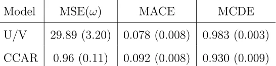
Model MSE(ω) MACE MCDE
U/V 29.89 (3.20) 0.078 (0.008) 0.983 (0.003)
CCAR 0.96 (0.11) 0.092 (0.008) 0.930 (0.009)
Table 1: Comparison of the U/V model and CCAR model for wind speed and direction.
MCDE = 1
n
n
X
i=1
cos(θi−θˆi) (10)
Table 1 gives the calculated MSE, MACE, and MCDE values for the U/V model and the
CCAR model along with their standard errors. We see that there is pronounced significant
improvement, of almost 30 times, in the modeling of the wind speed. When we compare the
direction, we see that the two models are comparable.
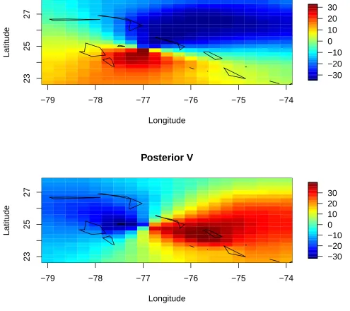
We also plotted the posterior means of the ui and vi for each model. Figure 4a when
compared to Figure 5a show that the U/V model may be over smoothing. Looking at the
third quadrant of each figure and comparing it to the response in Figure 2a we do not see
the spike in intensity close to the center in the U/V image that does appear in the CCAR
image.
6
Discussion and Remarks
In this paper, we present an innovative multivariate Bayesian spatial model for vector
fields, that we apply to hurricane forcing winds. We introduce for the first time in the
literature a spatial version of circular distributions, a circular conditional autoregressive
(CCAR) model for the vector direction. We implemented our framework for vector fields to
better characterize hurricane surface wind fields. A case study of Hurricane Floyd of 1999
compared our CCAR model to prior methods that decompose wind speed and direction into
its N-S and W-E cardinal components.
We analyze, in our case study, only responses from a single source, blended satellite data.
A second source of data, buoy measurements, can also be included to be combined with
−79 −78 −77 −76 −75 −74
23
25
27
Posterior U
Longitude
Latitude
−40 −30 −20 −10 0 10 20
−79 −78 −77 −76 −75 −74
23
25
27
Posterior V
Longitude
Latitude
−30 −20 −10 0 10 20 30
Figure 4: Posterior means of U and V for the U/V model.
structure. As future work we are planning to introduce a neighborhood structure that can
be more representative of the true neighbors within hurricane wind fields. Our case study
analyzed only one time point of Hurricane Floyd’s track towards the US East Coast. Our
−79 −78 −77 −76 −75 −74
23
25
27
Posterior U
Longitude
Latitude
−30 −20 −10 0 10 20 30
−79 −78 −77 −76 −75 −74
23
25
27
Posterior V
Longitude
Latitude
−30 −20 −10 0 10 20 30
Figure 5: Posterior means of U and V for the CCAR model
7
References
1. Banerjee S, Carlin BP, Gelfand AE (2004). Hierarchical modeling and analysis for
spatial data. Chapman and Hall, New York.
2. Chen Y. and Yau M.K. (2003). Asymmetric structures in a simulated landfalling
hurricane. Journal of Atmospheric Sciences, 60, 2294-2312.
3. DeMaria M. et al. (1992). A nested spectral model for hurricane track forecasting.
Monthly Weather Review, 120, 1628-1640.
4. Depperman R.C. (1947). Notes on the origin and structures of Philippine typhoons.
Bulletin of the American Meteorological Society,28, 399-404.
5. Fisher N.I. (1993). Statistical Analysis of Circular Data. Cambridge University Press,
Cambridge.
6. Georgiou P. (1985). Design Wind Speeds in Tropical Cyclone Prone Regions. Ph.D.
thesis, University of Western Ontario.
7. Holland G.J. (1980). An analytic model of the wind and pressure profiles in hurricanes.
Monthly Weather Review, 108, 1212-1218.
8. Morphet W.J. (2009). Simulation, Kriging, and Visualization of Circular-Spatial Data.
Ph.D. thesis, Utah State University.
9. Ravindran P. (2002). Bayesian Analysis of Circular Data Using Wrapped Distributions.
Ph.D. thesis, North Carolina State University.
10. Reich B. and Fuentes M. (2007). A Multivariate Semiparametric Bayesian Spatial
Mod-eling Framework for Hurricane Surface Wind Fields. The Annals of Applied Statistics,
11. Ross R.J. and Kurihara Y. (1992). A simplified scheme to simulate asymmetries due to
the beta effect in barotropic vortices. Journal of Atmospheric Sciences,49, 1620-1628.
12. Shapiro L. (1983). The asymmetric boundary layer flow under a translating hurricane.
Journal of Atmospheric Sciences, 40, 1984-1998.
13. Wang Y. and Holland G.L. (1996). Tropical cyclone motion and evolution in vertical
shear. Journal of Atmospheric Sciences,53, 3313-3332.
14. Xie L. et al. (2006). A real-time hurricane surface wind forecasting model: Formulation
and verification. Monthly Weather Review,134, 1355-1370.
15. Xie L. et al. (2010). A numerical study of the effect of hurricane wind asymmetry on
storm surge and inundation. Ocean Modeling. Submitted.
Appendix - The WN density in WinBUGS
In this section we give the WinBUGS code used to specify the WN density for the vector
angles. The remaining code for the vector length model, and all hyperpriors are omitted
since they are straight-forward to code in WinBUGS. The WN likelihood is given by
for(i in 1:n){
y[i]~dnorm(meany[i],tau2)
one[i]<-1
one[i]~dbern(denom[i])
meany[i]<-mu2[i] + 2*pi*K[i]
K[i]<-trunc(-z[i]/(2*pi))+1
z[i]~dnorm(mu2[i],tau2)
U[i]<-phi(sqrt(tau)*(2*pi-mu2[i]))
denom[i]<-c/(U[i]-L[i])
}
wherec=exp(−200) is a small constant used in the “ones trick” to ensure that denom[i]∈
(0,1). The product of the normal density for y[i] and the Bernoulli density for one[i]
gives the truncated normal density in (4). The combination of models for K[i] and z[i]