CODE DEVELOPMENT FOR PIPING INTEGRITY ASSESSMENT WITH
RESPECT TO NEW GERMAN SAFETY STANDARD
Klaus Heckmann1and Jürgen Sievers2
1
Technical Expert Structure Mechanics,
Gesellschaft für Anlagen- und Reaktorsicherheit (GRS) gGmbH, Germany
2Chief Expert Structure Mechanics,
Gesellschaft für Anlagen- und Reaktorsicherheit (GRS) gGmbH, Germany
ABSTRACT
The GRS-code PROST for deterministic and probabilistic integrity assessment of piping and vessels has been further developed to perform fatigue evaluation according to crack formation, to assess growth of cracks and leaks in terms of leak and break probabilities as well as to calculate leak rates for leak-before-break assessments. Crack growth can be considered due to the damage mechanisms fatigue, stress corrosion cracking, and ductile tearing as well as combinations of these. Uncertainties in material properties, loading assumptions, geometric dimensions as well as methodological aspects can be considered, i.e. especially several models to calculate stress intensity factors, leak areas and leak rates are implemented. The capabilities of PROST serve as a consequent implementation of the assessment steps concerning the break preclusion concept, as prescribed by the newly developed German safety standard KTA 3206. Generic application examples of KTA 3206 are described. Another example is the assessment of a very small crack-like leak near the drainage pipe of a German steam generator concerning possible consequences of further crack growth due to stress corrosion cracking. The validation of the PROST features is an ongoing process. Concerning the fracture mechanical tools several tasks concerning calculation of stress intensity factors have been performed in the framework of the international benchmark BENCH-KJ. The leak area- and leak rate methodology has been qualified by calculating several hundred measured results from different leak rate experiments. The work has been predominantly performed in the framework of the Reactor Safety Research Program of the German Federal Ministry of Economics and Technology. The work on aspects of KTA 3206 was supported by the German Federal Ministry for the Environment, Nature Conservation, Building and Nuclear Safety.
INTRODUCTION
For structural integrity assessment of piping components, several consecutive levels of integrity analysis are prescribed by safety standards. After proofing the design of an intact passive component, crack-like defects can be postulated, and fracture mechanical methods are applied in order to assess the integrity of the flawed structure and estimate the growth of the crack and its consequences. As a last step, a crack-like leak can be postulated, verifying that the leakage rate of a small, stable crack is large enough to be detected, which exclude a break (leak before break). The GRS-developed codes PROST and WinLeck, see Heckmann et al. (2015) and Heckmann et. al. (2014), respectively, serve as simulation tools for these complementary stages of a piping component structural integrity assessment based on regulations included in the new German Safety Standard KTA 3206 (2014).
FROM CRACK FORMATION TO CRACK GROWTH AND LEAK RATES
formation. One offered possibility to describe crack formation is the application of Wöhler curves: a specimen under fatigue load is cracked as soon as a certain fatigue damage level is reached. Another possibility is a crack formation rate, which is suitable for incorporating operational experience and simulating corrosion crack initiation.
Cracked specimens under loading are the next stage. The growing of the flaws can be described by various models for different damage mechanisms. Fatigue crack growth, corrosion crack growth and ductile tearing are the mechanisms which can be applied, also combinations of these are allowed. Fatigue crack growth models according to Paris and Erdogan (1963), Walker (1970), Forman (1972), Forman and Mettu (1992), Shack and Kassner (1994) and ASME (2013) are supported; stress corrosion crack growth approaches by Ford (1990 and 1991), Hüttner (2003), Brickstad (2004), Roth (2005), as well as Bosch and Van Dyck (2009) are available.
The assessment of the flawed structure (and the determination of failure) can be done by multiple approaches, including the SINTAP/FITNET failure assessment diagram: levels 0 to 3 are supported, the reader is referred to Kocak (2006) for details. In the cracked stage, transition from surface cracks to leaks and the growth of leaks can be considered. In the leak stage, crack opening areas and leak rates can be computed. The leak rates can be compared to the detection threshold of a leak surveillance system. This approach takes into account the leak before break concept, and distinguishes between leaking, leak detection and structural breaks occurring in a piping system of a plant. The effect of in-service inspections and hydrostatic testing during operation can also be simulated. Deterministic analyses and probabilistic determinations of failure probabilities are possible: initial crack size, material properties and loads might be simulated as statistically distributed parameters.
VALIDATION EXAMPLES
Fracture Mechanical Methods, BENCH-KJ
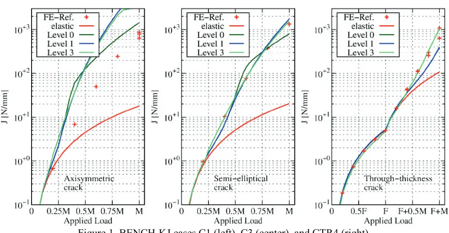
The PROST code has implementations of several simplified fracture mechanical methods for the computation of stress intensity factors, limit loads, and J-integrals, which are based on ASME (2013), British Energy R6 Code (2001), Busch et al. (1995), Zahoor (1991), and others. In the benchmark on analytical evaluation of the fracture mechanic parameters K and J for different components and loads (BENCH-KJ), such formulations are investigated and compared, see Marie and Faidy (2013). By participating in the comparative study, the implemented formulations in PROST are validated. As an example, test cases for three different crack shapes for circumferentially-oriented cracks at the inner side of a pipe wall are shown in Figure 1.
Figure 1. BENCH-KJ cases C1 (left), C3 (center), and CTR4 (right), J-Integral as a function of applied loading.
Leak Area And Leakage Rate Methods
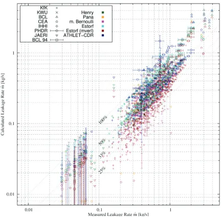
Leakage rate computation requires methods for leak opening area estimation as well as for the discharge flow rate calculation. The methods in the WinLeck code for the fluid discharge description are described in Henry (1970), Pana (1978), Grebner et al. (1996), and Estorf (2011). Additionally, a coupling to the ATHLET-code allows computations with the CDR-method. The validation is done with large number of experimental measurement points (about 750) from different sources. Leakage rate experiments described by Amos and Schrock (1983), Collier et al. (1984) at BCL, Matsushima et al. (1987) and Yano et al. (1989) at IHHI, John et al. (1987) at Kfk, Kefer et al. (1988) at Siemens/KWU, Isozaki et al. (1990) at JAERI, Paul et al. (1994) at BCL, Grebner et al. (1994) at PHDR, Michel et al. (2004) at CEA Cadarache, Revankar et al. (2013), and others are used for the validation. A typical example for the validation of leak rate methods is given in Figure 2.
Figure 2. Leakage rate as a function of crack opening. Measured in the HDR experiment E22.05 documented in Grebner et al. (1994) are compared to computations with different leak rate models.
Almost all computational results are well situated below the measured values. The few exceptions and their implications on the discharge flow models as well as a critical analysis of the plausibility of single experimental values are further investigated.
FRACTURE MECHANICS ANALYSIS PROCEDURE IN THE SAFETY STANDARD KTA 3206
The break preclusion procedure according to KTA 3206 (2014) includes a fracture mechanics analysis for piping based on seven consecutive steps.
- First, an initial crack of a specific size is postulated.
- In the second step, the growth of the flaw during the operation of the component is calculated.
- In step three and four, the critical (leak before break) length and the critical depth of a crack are calculated, respectively, assuming operational load as well as specific accident conditions.
- The fifth step assumes that a local leak is formed, and the leak rate is computed. By varying the length of the assumed wall-penetrating flaw, the length corresponding to the detectable leakage rate is computed.
- In the sixth step, the size of the grown flaw is compared to both the critical depth and the critical length; the corresponding computed sized at the end of the operation has to be smaller than the critical one.
- The seventh step (leak-before break) supposes that a leak is formed anyway, and the size of the detectable leak has to be smaller than the critical leak size. In this step, the leak opening area has to be underestimated, while frictional pressure losses have to be overestimated in order to obtain a conservative result. If the leak before break behaviour cannot be verified, the effect of in-service inspections can be considered for excluding any leak by limiting the possible crack depth. The safety assessment of the pipe is successful if step six and seven are positive.
Application Example
As an illustration of the procedure, a ferritic pipe of diameter 864 mm (wall thickness: 52 mm without cladding) is analysed, following an example case in KTA 3206 (2014). The operation conditions are 158 bar pressure and 319 °C temperature. The postulated crack has a depth of a= 5.2 mm and an aspect ratio
c/a = 3. The crack growth due to fatigue during 240 start-up and shut-down operations in 40 years is calculated as well as the critical crack size. The result (corresponding to steps one to four of the procedure) is shown in Figure 4.
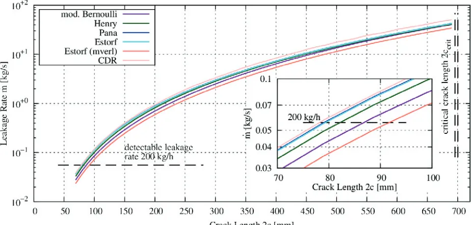
The growth of the postulated flaw is very small. The deepening in 40 years of operation is 0.1 mm, while the growing in length is even smaller. The critical crack sizes (computed with different methods in this example) differ by factors of more than 20 from these dimensions. Hence, the examination steps one to four and six are successful. In the leak before break assessment step five the detectable leakage rates (200 kg/h) has to be compared to the discharge flow rate passing a (subcritical) crack. The leakage rate as a function of the leak length is shown in Figure 5.
Figure 5. Leakage rate as a function of the crack length, calculated with different models.
The leakage rate at crack sizes close to the critical length is about 40 kg/s, the detection threshold is passed for much smaller leaks (about 80-90 mm full length). While Henry-, Pana-, Estorf- and CDR-model are best-estimate CDR-models applied with conservative assumptions of leak opening area and frictional resistance, Estorf-mverl and the modified Bernoulli equation (at the given parameters) are additionally conservative by thermal hydraulic modelling. Thus, the leak before break behaviour is confirmed.
Generic example cases from probabilistic studies
In order to reveal the effectiveness and strictness of the fracture mechanical analysis procedure within the KTA 3206 preclusion concept for nuclear piping, a number of generic test examples for piping components from literature has been examined. The presentation of the parameters are kept short here, the reader is referred to the original reports and articles for details.
Table 1: Parameters of generic cases and break preclusion steps
Case Large Medium Small Sample 4 Sample 9 RL23
Reference NURBIM PRAISE MPA
Geo-metry D[mm] t[mm] 861 62.2 324 33.3 88.9 11.1 863.6 63.5 127 12.7 406 190.5 Material NURBIM Base case, mean values flow stress 300 MPa 1.5403 Operational
Loading
p=156 bar, T=320°C
!primary,!secondary
20 000 cycles
p=165 bar, T=290°C
!weight,!thermal
280 cycles p=58 bar M=22 kNm 240 cylces Accident Loading
NURBIM design limiting event seismic event p=7.9 bar M=298 kNm Leak Detection 0.056 kg/s 0.19 kg/s 0.056 kg/s
Fracture mechanical analysis steps according to KTA 3206
Step 1 a0[mm]
c0[mm]
12.44 37.3 8.88 26.64 3.33 9.99 12.7 38.1 3.81 11.43 3.75 11.25 Step 2 ae[mm]
ce[mm]
15.8 38.0 10.7 27.0 3.49 10.02 12.72 38.1 3.82 11.43 5.35 12.12 Step 3 ccrit PGL KWU 388 mm 180 mm 141 mm 65 mm 37.8 mm 17.5 mm 423 mm 209 mm 117 mm 50 mm 168 mm 119 mm Step 4 ae<acrit ae<acrit ae<acrit ae<acrit ae<acrit ae<acrit
Step 5 cdet 45 mm 45 mm 32 mm 70 mm 40 mm 55 mm Step 6 integrity
confirmed integrity confirmed integrity confirmed integrity confirmed integrity confirmed integrity confirmed Step 7 LBB LBB (no LBB) LBB LBB LBB
All six example cases show a minor fatigue crack growth, although it is very small in the PRAISE examples. In all cases, the final crack size is subcritical, and thus the step 6 is successful, the integrity is confirmed. The half-length of a detectable leak, cdetis in the range of 32-70 mm. The case shows leak-before-break behaviour (step 7 successful) for all cases except for the NURBIM case ‘Small Pipe’, where the calculated critical crack length is just in the range (or even smaller, depending on the method) than the detectable length. In this case, the safety standard KTA 3206 would require in-service inspections or operational monitoring.
ANALYSIS OF A SMALL STEAM GENERATOR LEAK
A real leakage detected at the drainage pipe of a steam generator of a German PWR type Konvoi was analysed with the PROST code. The location is the bottom of the steam generator calotte. A narrow flaw was found in the circumferential weldment of the inset exhaust pipe, causing a minor leakage of few kg in several months. The small-scale leakage (INES 0) is described in Bundesamt für Strahlenschutz (2013), the situation is sketched in Figure 6.
Figure 6. Position of the drainage pipe at the bottom of a steam generator of a PWR (left), detail of the pipe inset and the crack position in the welding (right)
In order to assess consequences of further growing of the crack, the stress corrosion cracking model proposed by Bosch and Van Dyck (2009) is applied. The treatment of the geometry is simplified by assuming a stress enhancement by the pipe inset notch. Possible limits of crack growth are the penetration of the welding and the circumferential closure of crack around the drainage pipe. The quantitative results of the duration up to these events are depictured in Figure 7.
SUMMARY
The computer codes PROST for the quantitative evaluation of the structural reliability of pipe components and WinLeck for the calculation of leak rates have been further developed. Thereby models in PROST were provided and tested for the consideration of various damage mechanisms to determine leak and break probabilities in cylindrical structures of reactor steels and the number of leak rate models in WinLeck has been increased to perform comparative analyses. The deterministic procedures of the codes have been validated against a large number of experiments as well as benchmark activities, which is an ongoing effort. For the demonstration of break preclusion for pressure retaining components in nuclear power plants, the recently published safety standard KTA 3206 determines the requirements especially on fracture mechanical analysis including leak-before-break assessment. For this procedure, it has to be ensured that a through-wall crack is subcritical with respect to instable growth, and that the resulting leakage under stationary operation conditions can be detected by a leak detection system, i.e. in application cases the leak rate has to be underestimated.
REFERENCES
The American Society of Mechanical Engineers (2013). ASME Boiler & Pressure Vessel Code, Vol. XI: Rules for In-service Inspection of Nuclear Power Plant Components.
Amos, C. N., Schrock, V. E. (1983). “Critical discharge of initially subcooled water through slits,” NUREG/CR-3475
Bosch, R. W, and Van Dyck, S. (2009): “SCC Pilot Study RA3,” NULIFE Report No. NULIFE (08) 23 Brickstad, B. (2004). “WP-4 — Review and Benchmarking of SRMs and Associated Software,”
NURBIM Report D4, Appendix A1, SCC benchmark study.
British Energy, BNFL Magnox Generation, AEA Technology (2001). “Assessment of the Integrity of Structures Containing Defects,”R6-Revision 4
Bundesamt für Strahlenschutz (2013). “Short Description and Analysis of Nuclear Events in Germany in October 2010,” (in German) Störfallmeldestelle, Salzgitter, Germany
Busch, M., Petersilge, M., and Varfolomeyev, I. (1995). “Polynomial Influence Functions for Surface Cracks in Pressure Vessel Components,” IWM-Bericht Z 11/95, Fraunhofer IWM, Freiburg, Germany
Collier, R. P., et al.(1984). „Two-Phase Flow Through Intergranular Stress Corrosion Cracks and Re-sulting Acoustic Emission,“ EPRI NP-3540-LD
Estorf, M. (2011). “Leckratenberechnung,” Contributions to the working group of the safety standard KTA 3206 , Germany
Ford, F. P. (1990). “The crack-tip system and its relevance to the prediction of cracking in aqueous environments,”Proc. First Int. Conf. on Environment-Induced cracking of Metals, pp 139-162 Ford, F. P., et al. (1991). “Stress corrosion cracking of low-alloy steels in high temperature water,”5th
Int. Symp. on Environmental Degradation of Materials, 561--570
Forman, R. G. (1972). “Study of fatigue crack initiation from flaws using fracture mechanics theory,”
Engineering Fracture Mechanics, 4(2), 333-345
Forman, R. G., and Mettu, S. R. (1992). “Behavior of surface and corner cracks subjected to tensile and bending loads in a Ti-6Al-4V alloy,” In: Ernst, H.A., Saxena, A., McDowell, D.L. (Eds.), Fracture Mechanics 22th Symposium, vol. 1. American Society for Testing and Materials, Philadelphia, 519--646 ASTP STP 1131
Grebner, H., Höfler, A., and Hunger, H.(1994). “HDR Safety Program. Investigation of Discharge Rates of Leaks in Small-Scale Piping,” (in German)Technischer FachberichtPHDR 125-94
Grebner, H., Müller, C., and Sievers, J. (1999). “Development of analysis techniques and generic analyses of components under beyond design loading conditions,” (in German) GRS-A-2678, GRS, Germany Harris, D. O., Dedhia, D. D., and Lu, S. C (1992). “Theoretical and User’s Manual for pc-PRAISE,”
Heckmann, K., Bläsius, C., and Sievers, J. (2014). “WinLeck,” Documentation, GRS-P-6, Rev. 4, Vol.1-2, GRS, Cologne, Germany
Heckmann, K., Bläsius, C., and Sievers, J. (2015). “PROST,” Documentation, GRS-P-7, Rev. 3, Vol.1-4, GRS, Cologne, Germany
Henry, R. E. (1970). “The two-phase critical discharge of initially saturated or sub-cooled liquid,”Nucl. Sci. Engng.41, 1970, 336-342
Hüttner, F. (2003). “Evaluation of experimental results for crack growth in power plant steels,” (in German)MPA Final Report,MPA-Auftrags-Nr. 8884 01 001, Stuttgart, Germany
Isozaki, T., et al. (1990). “Measurement of Leak-Rate Through Fatigue-Cracks in Pipes under Four-Point Bending and BWR Conditions,”Int. J. Pres. Ves. Pip.43 399-411
John, H., Reimann, J., and Eisele, G. (1987). “Critical leak flow through rough cracks in pressure vessels,” (in German)Kfk4192, Kernforschungszentrum Karlsruhe, Germany
Kefer, V., et al. (1988). “Accuracy of leakage rate models for cracks in pressure retaining components,” (in German)Dechema-Monographien,Band 111, VCH Verlagsgesellschaft, Germany
Kocak, M. (2006). “FITNET - European Fitness For Service Network,” Final Technical Report, GKSS Forschungszentrum, GTC1-2001-43049, Germany
KTA Safety Standard 3206 (2014): “Verification Analysis for Rupture Preclusion for Pressure Retaining Components in Nuclear Power Plants,” Salzgitter, Germany
Lerchl, G., et al. (2012). “ATHLET,” Documentation GRS-P-1, Rev. 6, Vol. 1-3, GRS, Garching, Germany
Marie, S. and Faidy, C. (2013). “BENCH-KJ: Benchmark on analytical evaluation of the fracture mechanic parameters K and J for different components and loads,” Revision 5, March 2013, AEN NEA / IAGE, OECD
Michel, B., et al. (2004). “Leak rate assessment in the leak before break analysis of a PWR piping system,” INIS—FR—480 33/04 FR0108177, CEA Cadarache, France
Paris, P. C., and Erdogan, F. (1963). “A Critical Analysis of Crack Propagation Laws,”Journal of Basic Engineering, Transaction ASME D 85 528-534
Pana, P., and Müller, M (1978). „Subcooled and Two-Phase Critical Flow States and Comparison with Data,“Nucl. Eng. Design45, 117-125
Paul, D. D., et al. (1994). „Evaluation and Refinement of Leak-Rate Estimation Models,“ NUREG/CR-5128
Revankar, S. T., Wolf, B., and Vadlamani, A. (2013). “Assessment of Leak Rates through Steam Generator Tubes,” Canadian Nuclear Safety Commission, RSP-0294, Purdue University, Canada Roos, E., Schuler, X., Wackenhut, G., and Lammert, R. (2008). “Probabilistic safety assessment of
components.” 34thMPA-Seminar,55.1, Stuttgart, Germany
Roth, A., et al. (2005). “The Effect of Transients on the Crack Growth Behaviour of Low Alloy Steels for Pressure Boundary Components under Light Water Reactor Operating Conditions,” 12th International Conference of Materials in Nuclear Reactors – Water Systems, Paper No. 208, Salt Lake City, Utah, USA
Schimpfke, T. (2004). “Nuclear Risk-Based Inspection Methodology for passive components (NURBIM),”NURBIM project, WP-4, Appendix B
Shack, W. K., and Kassner, T. F. (1994). “Review of Environmental Effects on Fatigue Crack Growth of Austenitic Stainless Steels,” NUREG/CR-6176, ANL-94-1
Walker, E. K (1970). “The effect of stress ratio during crack propagation and fatigue for 2024-T3 and 7076-T6 aluminium,” in: Effect of environment and complex load history on fatigue life, ASTM STP 462. Philadelphia: American Society for Testing and Materials, pp.1--14
Yano, T., Matsushima, E., and Okamoto, A. (1987). “Leak flow rate from through-wall crack in pipe,”
ASME-JSME Thermal Engineering Joint Conference, 301