20th International Conference on Structural Mechanics in Reactor Technology (SMiRT 20) Espoo, Finland, August 9-14, 2009 SMiRT 20-Division 3, Paper 1814
Complex FEM based system of computer codes to model nuclear fuel rod
thermo-mechanical behaviour
Mojmír Valach
a, Martin Dostál
a*, and Ji í Zymák
aa
Nuclear Reseach Institute, e plc, 120 68 e -Husinec 130, Czech Republic, e-mail: [email protected]
*
corresponding author
Keywords: Thermo-mechanical behaviour, finite element method, pellet-cladding contact, friction coefficient.
1
ABSTRACT (NO MORE THAN 200 WORDS)
The paper presents long-term effort to establish closed chain of computer codes, which allow computer modeling of the thermo-mechanical fuel rod behaviour from the 1D representation to the 3D detailed problem description. The whole complex uses the same FEM based mathematical approach. The principle of this modular approach is to handle boundary and initial conditions by the similar transfer independent on the complexity of solved problem. Recently we have combined the FEMAXI integral code (1-2D axi-symmetrical approach) to the full 2D r-z global model of fuel pin ending at 2D (r-z, r-) and 3D local detailed submodels. The system of codes is connected (coupled) by data transfer. All the submodels are stand-alone. The same is valid for the material data properties.
To illustrate the whole approach the exact chain of the simulation is as follows: RODBURN, FEMAXI-6, TF(thermo-physical)_global, TFM(thermo-physical mechanical)_r-z/r- _local and FRA-TFM_3D_local (one pellet and two pellet contact configuration, one half cracked pellet–clad contact in 3D).
Fuel Rod FEM based simulator was developed at the NRI e plc for EZ, a.s. (Czech power/electricity producer). The development was performed in the COSMOSM FEM software product of S.R.A.C. California, U.S.A.
The FRA_TFM versions are using nonlinear thermal solver (HSTAR), static mechanics solver (STAR) and nonlinear (NSTAR) mechanics COSMOSM solver. All materials, thermophysical properties as well as mechanical properties are prepared in the form of COSMOSM library – functions and material curves with temperature dependence and time (expressing burn-up process).
We would like document examples of simulations results of all the described modeling levels.
2
INTRODUCTION
Thermo-mechanical behavior of a nuclear fuel rod is still one of the most difficult fields for mathematical-physical modeling despite the quick development of hardware and software suitable for these tasks. The position of traditional approach represented by integral code applications at steady-state and transient conditions is still indispensable due to the physical complexity and numerical difficulty in these computer simulations.
The goal of our modeling work was to develop model capable of computing the spatial distribution of temperature and stress-strain in the fuel and cladding especially during power transients. Developed local models of nuclear fuel rod can be mainly used for modeling the stresses and deformations in the pellet-cladding contact point. The margin to possible failure of pellet-cladding, that may appear as a consequence of large power changes, can be predicted by this way. Global model enables effectively calculate detailed temperature distribution in the whole fuel rod (including end plugs and spring).
how accurately the geometry, the material behavior and the boundary conditions of the actual problem are idealized. One has to take into consideration that all real structures are nonlinear in some way.
3
THERMO-MECHANICAL MODELING CHAIN
3.1 RODBURN and FEMAXI-6 modeling
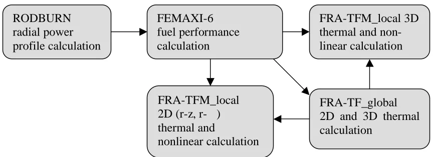
The radial power profile and detailed burnup distribution during base irradiation and ramp condition is calculated by the means of RODBURN code Uchida (1993). RODBURN is a code for burnup analysis based on nuclear reaction theory. Its output can be incorporated into 6 fuel performance code. FEMAXI-6 Suzuki (2005) is a finite element based fuel analysis code with complete coupled solution of thermal and mechanical analysis. The result of FEMAXI-6 calculation of base fuel irradiation produces some boundary and initial conditions for FRA-TF_global modeling as shown in Fig. 1. The calculation of base irradiation and power ramp produces some boundary and initial conditions for FRA-TF_local modeling (see Fig. 1).
Figure 1. Computational chain of the calculation sequence
3.2 FRA-TFM modeling
FRA-TFM modeling is based on the COSMOSM system where various models of nuclear fuel rod were developed. 2D and 3D modeling effort started with small configurations as half pellet (axially symmetrical) and then the gained experience was used to create a global model of the full fuel rod. Developed applications were named by acronym FRA (Fuel Rod Analyser) and further specification is expressed as -TF (thermo-physical model) or -TFM (thermo-(thermo-physical mechanical model) and according to geometry local (_local) or global (_global). Special input data complementary set is needed from fuel performance code calculation (in our case FEMAXI code is used) or from measurements for the simulation of power ramp. Axial symmetry is considered in symetrical r-z geometries. Local models (r-z and r- ) are used to calculate thermo-mechanical fuel behaviour during power ramps while global models are used for steady state thermal fuel behaviour.
3.2.1 Boundary and initial conditions
Heat transfer coefficient, coolant temperature and its time history (usually considered as it begins in cold state at room temperature and after ramp it returns to the cold state at room temperature) are given for thermal calculations.
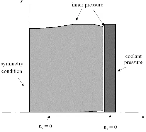
Mechanical boundary conditions (shown in Fig. 2) in nonlinear r-z calculations are used additionally to
RODBURN
radial power
profile calculation
FEMAXI-6
fuel performance
calculation
FRA-TF_global
2D and 3D thermal
calculation
FRA-TFM_local
2D (r-z, r- )
thermal and
nonlinear calculation
of power ramp
is applied to inner surfaces. The first is given and the latter is as time history gained from FEMAXI-6 fuel performance calculation or measurement. The data transfer is made automatically.
Pellet-cladding contact considers „Coulomb“ model with friction coefficient 0,5 and with sliding (whether the sliding is applied or not determines the solver). The influence of different friction coefficient values (parametric calculations) on cladding stress is discussed in section 4.
Figure 2. Mechanical boundary conditions
3.2.2 Material properties
All models share the same set of material properties mainly based on MATPRO-9. Materials are consistent with the ones used in FEMAXI-6 calculations, also for comparison reasons.
In COSMOSM system, materials are defined as temperature dependent for appropriate burnup. Six material sets are prepared – UO2 pellet, UO2 with different elastic modulus, helium in gap, gas mixture of
helium and fission gases in gap, cladding (Zircaloy-4), oxide layer. Pellet is considered as “nonlinear elastic” with elastic modulus and Poisson constant changed by considering four cracks according to Oguma (1983).
The cladding is modeled as elasto-plastic (von Mises model) with isotropic hardening. Plasticity condition
0
3
"
!
=
=
yF
#
#
, (1)where
(
) (
) (
)
[
2]
1 3 2 3 2 2 2 1 5 ,
0
!
!
!
!
!
!
!
= " + " + " is effective stress,i
!
, i = 1,2,3, are principal stresses,y
!
is yield stress.Pellet swelling is for calculations modeled by higher thermal expansion coefficient according to the FEMAXI-6 calculation.
Pellet and cladding creep is in COSMOSM modeled according to classical creep law (Bailey-Norton):
) / ( ) ( ) (
0 C1 C2 C T
c
C
t
e
! T" " "
=
#
$
(2)4
FRA-TFM_LOCAL MODELLING
4.1.1 2D models
Few 2D, FE axi-symmetrical along longitudinal axis, local models of nuclear fuel rod were developed. There are half pellet (see geometry in Fig. 2), one pellet (i.e. half pellet with full pellet height is modeled), two pellets (pellet-cladding and pellet-pellet contact is considered) in r-z geometry. Some results of elastic calculations with r- models were presented in Belac (2005).
2D local half pellet model considers pellet dishing and chamfering and arbitrarily central hole. Equivalent part of cladding and pellet-cladding gap are also meshed. Fuel pellet axial position in the fuel rod can be chosen at any location, however, the most effective is the position with maximum linear heat rate. Pellet is modeled with or without radial crack. 2D nonlinear 4-node isoparametric elements PLANE2D are used for thermal and nonlinear analysis and 2D nonlinear 2-node contact elements GAP are used for pellet-cladding contact.
The pellet has 50 finite elements (FE) axially and 33 FE radially (pellet is divided into five parts and the number of elements rises towards the periphery). The cladding is radially divided into 13 FE one of them on the inner part can represent oxide layer as well as two FE on the outer part. When calculating burn-up case, the initial dimensions are transferred from the previous FEMAXI-6 calculation. Geometrical dimensions of pellet and cladding before ramp, power ramp parameters (coolant, power history, inner gas pressure during ramp, material characteristics) are combined. Input file for FRA-TFM is generated automatically.
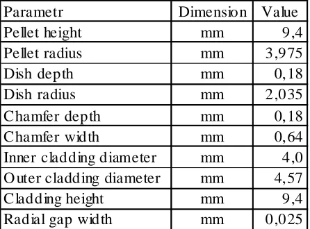
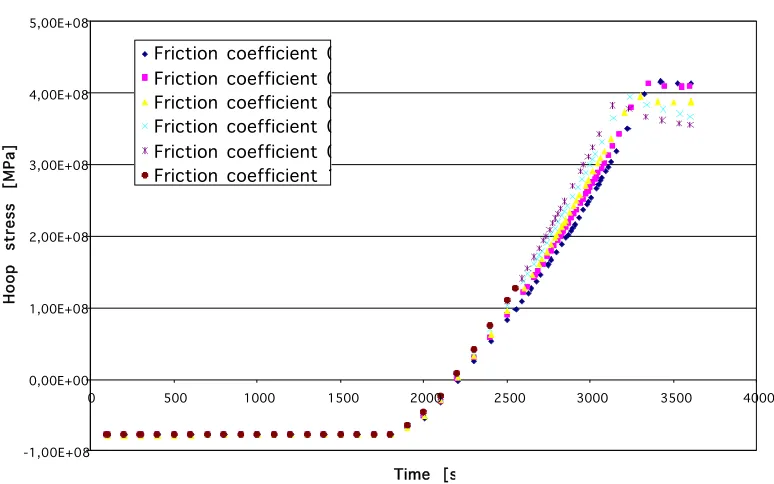
The influence of friction coefficient to the cladding hoop stress was estimated by parametric calculations with power increase from zero to 300 W/cm during one hour. Geometric dimensions of the half pellet configuration are listed in Tab. 1. The pellet was considered without cracks, i.e. with nominal elastic modulus, to maximize stress. Calculated temperature history in the pellet centre, outer pellet surface, inner and outer cladding surface is shown in Fig. 3. The values used for friction coefficient were 0; 0,2; 0,4; 0,6; 0,8 and 1; yield stress was considered 500 MPa. As the representative node was chosen the one in the contact area of pellet edge with cladding. Calculated hoop stress at the inner cladding surface in this node for different friction coefficients is shown in Fig. 4. Based on these calculation can be concluded that the higher friction coefficient is the shorter time is needed for hoop stress rise and plastification and smaller stress at the inner part of cladding is achieved.
Table 1. Geometrical dimensions of pellet and cladding.
Parametr Dimension Value Pellet height mm 9,4 Pellet radius mm 3,975
Dish depth mm 0,18
0 500 1000 1500 2000 2500
0 500 1000 1500 2000 2500 3000 3500 4000
Time [s]
T e m p e ra tu re [K ]
Pellet center Pellet outer surface Cladding inner sufrace Cladding outer surface
Figure 3. Temperature history during considered power rise
-1,00E+08 0,00E+00 1,00E+08 2,00E+08 3,00E+08 4,00E+08 5,00E+08
0 500 1000 1500 2000 2500 3000 3500 4000
Time [s]
H o o p st re ss [M P a]
Friction coefficient 0.0 Friction coefficient 0.2 Friction coefficient 0.4 Friction coefficient 0.6 Friction coefficient 0.8 Friction coefficient 1.0
Figure 4. Hoop stress in the inner surface of the cladding for different friction coefficients
4.1.2 3D models
Three 3D local models were in fact finalized – half pellet, one pellet and two pellets (all with appropriate part of cladding). 3D nonlinear 8-node elements SOLID were used in all cases. For contact between pellet and cladding were used non-linear contact elements GAP (node-surface type).
tentatively decreased as mentioned in the section 3.2.2. The von Mises stress in the cladding is shown in fig. 6. The corners of pellet fragments impose higher stress in the cladding.
Figure 5. The result of 3D steady state calculation with linear heat rate 300 W/cm
Figure 6. Von Mises stress distribution in the 3D local model
4.1.3 Typical radial configurations of contact problems
In this section we would like rise some open questions and ideas of high burn-up pellet-cladding contact problem. When developing a pellet-cladding contact model one can state that the mechanical thermo-physical properties of contact layer are in fact unknown. The bonding contact layer can be caused by two types of conditions: low temperature and low contact pressure (1) and high temperature and high contact pressure (2).
Another issue is how important is ZrO2 for mechanical state contact solution? Two types of ZrO2 layer
5
FRA-TF_GLOBAL MODELLING
The model of the typical WWER-1000 rod was created as 2D axi-symmetrical along the longitudinal axis. It consists of the complete portion of parts of the real rod, i.e. lower end plug, 14 naturally enriched fuel pellets at the bottom part of the fuel stack, 354 enriched pellets, 14 naturally enriched fuel pellets at the top part of the fuel stack, plenum spring, upper end plug and Zry4 cladding. For the temperature calculations the spring is substituted with a hollow cylinder and for the mechanical calculation with a special finite element that is able to compress. Axially, the rod is divided into 354 + 2x14 + 3 (enriched pellets, naturally enriched pellets, lower end plug, upper end plug, spring) non-equal parts which is effectively used for boundary convection condition for heat transfer. Inlet coolant temperature is assigned to lower eng plug and lower naturally enriched pellets. Then, linear (of course can be incorporated any other/different) coolant temperature increase follows with the outlet temperature in the part with spring and in upper end plug. Geometrical dimensions are nominal as fabricated and temperature dependent material properties of parts are standard (adopted from the FEMAXI-6 code Suzuki (2005) – also because of the comparison possibilities). All definitions of boundary and initial conditions and material characteristics can be easily changed. Also gravitation is included. 4-node PLANE2D axi-symmetrical nonlinear elements were used.
Simulation of burn-up state is done in two ways. First, the geometry is changed in so way that the gap is smaller (in modeled cases 10 microns) and secondly the material properties are changed for the appropriate burn-up (nominal value is 50 GWd/tU). It is possible also to change the size of inner and outer oxide layer.
For non-steady state thermal calculation the “reference” four year power history, that can be arbitrarily changed, is chosen. Here it is necessary to simulate e.g. geometry of pellets and cladding, pellet and gap gas thermal conductivity. For decreasing thermal conductivity with burn-up modeling is used restart strategy when every four months coefficient of thermal conductivity of pellet is changed. Every month the gap thermal conductivity (decreasing due to released fission gases and gap closure) is changed according FEMAXI-6 calculation (the same power history is calculated).
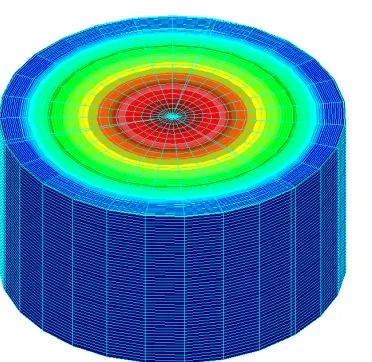
The example of result of thermal calculation with 2D model is shown in Fig. 7.
Figure 7. Temperature field with radial profile in the middle of the pellet (in Kelvins)
The application designed to calculate 3D steady state temperature field in the typical WWER-1000 fuel rod was also finished in COSMOSM 2.85.
3D model consists of lower and upper end plug and cladding in the real dimensions. The spring is for thermo-physical calculation replaced with a hollow cylinder. Fuel pellets were modeled in so way to stay within software meshing limits. After this simplification the pellet stack consists of 35 so called macro-pellets with preserved stack height. Dishing, chamfering and all radial dimensions are same as in the real pellet. Upper and lower macropellet is without heat sources (that corresponds with end pellets with naturally enriched uranium).
possible to input 3D thermal sources and anisotropic initial and boundary conditions. All used materials are temperature dependent.
Simulation of burned situation is made in two levels. First, the geometry is changed according to burn-up. Secondly, the material characteristics are changed to agree with the burn-up also. Special excel sheets are created and user can easy generate temperature dependent properties by changing the burn-up level. These material sets are exported into the COSMOSM working files.
We assume three „typical“ axial shapes: uniform, sinus axial profile, deformed – axial profile is deformed by the control rod. The example of result of thermal calculation with 2D model is shown in Fig. 7.
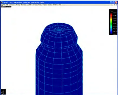
Examples of 3D model thermal calculation result are shown in Fig. 8 and 9.
Figure 8. Temperature field in the upper end plug (in Kelvins)
Figure 9. Result of calculation – temperature profile in cross-section (in Kelvins)
6
CONCLUSION
Paper concludes our long term effort in 2D and 3D modeling of nuclear fuel rod thermo-mechanical behavior. 3D fuel rod simulator was installed successfully and tested by our industrial sponsor.
REFERENCES
Belac, J., Valach, M. and Zymák, J. 2005. Influence of azimuth and radial neutron and thermal sources anisotropy on contact problem simulation in real fuel pellet-cladding configuration using FEM. SMiRT-18, Beijing, China, August 7-12, 2005.
COSMOSM 2.8 for Windows - online manuals, SRAC 2003.
Dostál, M., Valach, M., Zymák, J. and Svoboda, R. 2006. 3D FEM Based Fuel Rod Simulator FRA-TF. TopFuel 2006: International Meeting on LWR Fuel Performance, Salamanca, Spain, October 22-26, 2006.
Hughes, T. J. R. 1987. The Finite Element Method: Linear Static and Dynamic Analysis. Prentice Hall, Inc., Englewood Cliffs, New Jersey.
Oguma, M. 1983. "Cracking and Relocation Behavior of Nuclear Fuel Pellets During Rise to
Power", Nucl. Eng. Des., Vol. 76, pp. 35-45.
Suzuki, M. 2000. Light Water Reactor Fuel Analysis Code FEMAXI-V (ver. 1). Japan Atomic Energy Research Institute – Data/Code 2000-030, Japan.
Suzuki, M. and Saitou, H. 2005. Light Water Reactor Fuel Analysis Code FEMAXI-6 (ver. 1). Japan Atomic Energy Agency – Data/Code 2005-003, Japan.
Uchida M. and Saito H. 1993. RODBURN: A code for calculating power distribution in fuel rods, Japan Atomic Research Institute, JAERI-M, 93-108, Japan.
Valach, M. and Zymák, J. 2004. 2D Pellet-Cladding Modelling using FEM at NRI Rez plc. International seminar on pellet-clad interactions with water reactor fuels, Aix-en-Provence, France, 9-11 March 2004.
Valach, M., Zymák, J. and Dostál, M. 2005. 2D Pellet-Cladding Modelling using FEM at NRI Rez plc. – High Burnup Fuel Simulation. 2-3 March 2005, Fuel Safety Research Meeting 2005, Tokio, Japan.