An Efficient Algorithm for Simulating the Nonlinear, Transient Response of Preloaded
Structures within a Single Application
R. F. Kulak and P. A. Pfeiffer
Reactor Analysis and Engineering Division, Argonne National Laboratory, Argonne, IL 60439
ABSTRACT
Nuclear power plant structures are typically analyzed for either static or dynamic loading conditions. However, for certain accident scenarios there are situations in which it is necessary to perform both static and transient analyses. One of these situations arises when structures are under significant preload. The transient loading of mechanical components and structures is usually performed with the assumption that there are no preloads applied to them since preloads are usually small and can be neglected. However, for certain structures used in the nuclear power industry, the preloads are significant and must be considered in the transient analysis. Two examples of these types of structures are prestressed concrete containments and inter-compartment locks, which respond with both geometric and material nonlinearities during transient loadings. In order to handle these conditions, an efficient algorithm (computational engine) has been designed to first compute the response of a structure to static loading, which preloads the structure, and then, within the same computational run, computes the structural response to transient loading. To illustrate the benefits of the algorithm, a preloaded platen, which is part of an inter-compartment lock, is subjected to an impulsive load. The resulting static and transient responses of the system is presented.
INTRODUCTION
Solution algorithms used to obtain the response of structures subjected to fast transient loading, e.g., impact loading, are explicit integration schemes, such as the central difference algorithm. On the other hand, the response of structures to static loading have, traditionally been obtained through the use of implicit algorithms. For most problems encountered in industry, the choice of which type of code to use was straight forward and depended upon whether one was solving a static equilibrium problem or a transient dynamic problem. However, it is sometimes necessary to obtain the transient dynamic solution to structures that have significant preloads within them. For example, prestressed concrete structures are preloaded to stress levels that cannot be ignored in subsequent transient dynamic analysis. Another example, which is currently our main interest, is a preloaded inter-cell lock that is subjected to a drop-load that leads to a transient dynamic response of several of its components. Interestingly, the sheet metal industry has the inverse situation. The transient analysis of the stamping process is performed first, and then a static equilibrium analysis is performed to obtain the final shape of the stamping.
One approach to solving this type of problem is to first use a code designed for static equilibrium problems and obtain the static equilibrium displacement, strain and stress fields and then use these as initial states in a transient dynamic code. This may prove to be a difficult approach if the data structures of the two codes are different and impossibility if one is using commercial codes and does not have access to the source code. This approach would still require the execution of two codes with an intermediate data transfer step.
Here the goal was to develop a computational engine within a single application that would only require one execution and no data transfer. The NEPTUNE code [1] has been under continuous development at Argonne National Laboratory since the mid-seventies. The code has been developed in a finite element basis and designed to simulate the nonlinear, three-dimensional response of, in particular, nuclear structures to either static or transient dynamic loads. The code uses the central difference algorithm for transient analysis and the dynamic relaxation algorithm for static analysis.
This paper describes the seamless integration of the dynamic relaxation algorithm and the central difference algorithm into a computational engine that can simulate the response of preloaded structures subjected to impact loads. Initially the computational engine uses a modified dynamic relaxation algorithm, with self-determined parameters, to compute the static response of the structure due to the preload and, subsequently, invokes the central difference integrator to solve the transient dynamic equations
PRELOADING ANALYSIS
The robust dynamic relaxation algorithm [2,3,4,5] is used to find the preloaded configuration. The next subsection presents the form of the dynamic relaxation algorithm that we adopted.
Dynamic Relaxation Algorithm.
With the dynamic relaxation algorithm, the static equilibrium configuration is obtained as the damped solution to the dynamic equations of motion. The semidiscritized equations of motion are given by
iI (no sum), (1)
where iI is a diagonal mass matrix, f
int and f ext are the internal and external nodal forces, respectively, of node I in the ith direction, and the nodal displacement is uiI. The superposed dots indicate temporal derivatives, and the tilde indicates a pseudo mass. With the approach, the pseudo mass is used to control damping.
A modified form of the central difference integrator is used to solve the equations of motion. The acceleration, velocity, and displacement are updated according to
(no sum)
(2)
where
)
t is a fictitious time increment and n is the step number. Two parameters,"
1 and"
2, appear in the update for the velocity and they control the damping that is put into the system. The following forms are used to compute"
1 and"
2,(3)
where c is the damping and is determined from
(4)
where
T
R is the lowest participating frequency [4] of the system. The lowest participating frequency is calculated from the following approximate Rayleigh quotient(sum over i, I), (5)
where kiI is the approximate diagonal stiffness matrix computed from
(6)
Since the DR algorithm is an iterative solution procedure, it is necessary to use a convergence criteria to determine when the solution vector is close enough to the true solution. Euclidean norms for force balance and displacements are used to define acceptable equilibrium configurations.
IMPACT ANALYSIS
The impact aspect of the analysis is concerned with the short-duration transient response of the system. The central difference integrator has been proven to be one of the most efficient for these types of problems. The next subsection describes the basics of the integrator.
Central Difference Algorithm
The semidiscretized equations of motion for the translational degrees-of-freedom (dof) are given by
(no sum) (7)
where miI is a diagonal mass matrix, uiI is the nodal displacement of node I in the ith direction, and are the internal and external nodal forces, respectively. The rotational dof’s, which originate from the structural elements and the revolute element, take a slightly different form. The equations of motion are the Euler equations of rigid body dynamics:
(8)
(no sum on I)
where and are the nodal angular acceleration and angular velocity in the body coordinate system; and are the internal and external nodal moments, respectively; and IxxI, IyyI and IzzI are the principal moments of inertia. We note that for explicit integration of the equations of motion, the mass matrix must be diagonal. Equation (7)and (8) represents a set of uncoupled equations that are integrated on an individual basis.
The equations of motion are integrated using the central difference (CD) formulas. Since the equations are uncoupled, the accelerations are obtained from Eq. (7) which gives
(no sum) (9)
Note, all quantities on the right-hand side of Eq. (8) are known. The translational velocities and displacements are obtained from
(10)
(11)
The rotational dof’s are integrated in a slightly different way. The approach developed by Belytschko and Schwer [6] was used to integrate the rotational equations of motion. The central difference integrator is conditionally stable and appropriate formulas have been programmed into the code to assure stable calculations.
SEAMLESS INTEGRATION
The dynamic relaxation and central difference algorithms have a high degree of similarity in algorithmic layout. Because of this, the two algorithms have been seamlessly integrated into a new computational engine within the NEPTUNE finite element code. Some of the differences are briefly described below.
The stability of the central difference algorithm is satisfied when the calculational time step for each element is less than or equal to the critical time step. The counterpart for the dynamic relaxation algorithm, as formulated here, is that the pseudo density of each element must be greater than or equal to the critical or minimum density.
of the static calculation (i.e., the DR algorithm) the switch to the transient analysis is made without any changes to arrays. Note, the dynamic relaxation algorithm uses the pseudo mass matrix and the central difference algorithm uses the normal mass matrix, which is based on physical density. The flowchart for the computational engine is shown in Table 1 below.
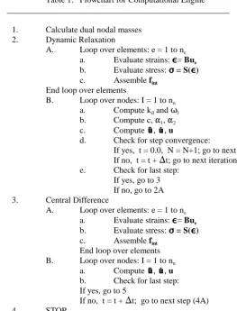
Table 1. Flowchart for Computational Engine ____________________________________________________
1. Calculate dual nodal masses 2. Dynamic Relaxation
A. Loop over elements: e = 1 to ne
a. Evaluate strains: ,,,,= Bue
b. Evaluate stress: FFFF = S(,,,,)
c. Assemble fint
End loop over elements
B. Loop over nodes: I = 1 to nn
a. Compute kiI and Tl
b. Compute c, "1, "2
c. Compute , , u
d. Check for step convergence:
If yes, t = 0.0, N = N+1; go to next step If no, t = t + )t; go to next iteration e. Check for last step:
If yes, go to 3 If no, go to 2A 3. Central Difference
A. Loop over elements: e = 1 to ne
a. Evaluate strains: ,,,,= Bue
b. Evaluate stress: FFFF = S(,,,,)
c. Assemble fint
End loop over elements B. Loop over nodes: I = 1 to nn
a. Compute , , u
b. Check for last step: If yes, go to 5
If no, t = t + )t; go to next step (4A)
4. STOP
____________________________________________________
APPLICATION
The above developments have been applied to the solution of a dynamic structural engineering problem. It is often necessary to transfer equipment and materials between compartments positioned one over the other. Access between compartments for equipment/material transfer is provided by an opened lock that allows a crane to place the equipment/material onto the platen. A scenario considered in the design of these systems is the capability of the supporting structure to handle drop loads.
System Description
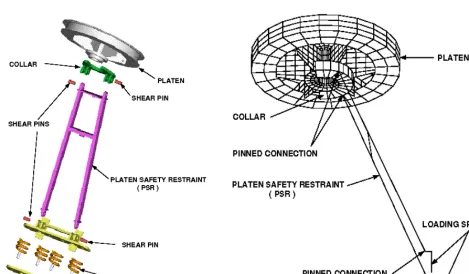
connection at its bottom so that it can rotate out from under the platen during transfers. Figure 1 shows some of the components of the system.
During normal equipment/material transfer, the support frame is rotated out from under the platen and the topside lid is opened. The equipment/material is placed on the platen that is then lowered to the floor level of the lower compartment. The equipment is removed from the platen, which is then raised up to the bottom of the penetration. The support frame is engaged and used to provide the preload to the platen, which creates a leak-tight seal between the two compartments. The lid in the upper cell is then closed.
To design the support frame properly, it is necessary to consider a scenario in which the lid is open and some drop-load impacts the platen. The remainder of this section describes the finite element model used in the dynamic simulation and some results obtained using the previously described computational engine.
Finite Element Model
A finite element model (Fig. 2) was developed for the above system and contains representations for the platen, ram and support frame. The full cylindrical shell of the penetration is not explicitly modeled. The bottom surface of the cylindrical shell is treated as a rigid boundary at which contact elements are located.
The platen, shown in Figure 2, is a fabricated structure consisting of a top plate, a middle annular-plate and a bottom plate (i.e., the platen collar). A pipe is located in the center of the platen between the top and bottom plates and forms the cavity in which the hydraulic ram is inserted. The three plates and central pipe are tied together by vertical stiffeners, and, in addition, the top and middle plates are tied together by an outer peripheral stiffener-plate. The diameter of the platen is about 80 in. and weighs approximately 4140 lbs. A total of 720 quadrilateral plate elements are used to model the platen.
Twenty-four contact elements are located between the top plate of the platen and the bottom surface of the cylindrical shell. Also, there are four platen guide-brackets mounted on the ceiling of the lower compartment, which are spaced 90 degrees apart, to keep the platen from moving horizontally. The effective length of the guide brackets is about 5 in. Contact elements are located between the peripheral stiffener-plate and the guide brackets.
Figure 3. Displacement Histories of Right, Center and Left Nodes on the Platen
Figure 4 Axial Force History in the Coil Springs
Figure 5. Temporal Evolution of the Impact Force on the Support Guide
preloading mechanism, which uses coil springs, is located at the bottom. The collar plate of the support frame mates with the collar of the platen. The tubular struts are pinned to the collar-plate at the top and the preloading mechanism at the bottom. A total of 20 three-dimensional beam elements are used to model the support frame and one spring element is used to model the coil springs. Thirty contact elements are located between the platen collar and the support-frame collar. The complete finite element model, which consists of the platen and the support frame, is shown in Figure 2.
Drop-Load Simulation
The model described above was subjected to a static preload of 31,000 lbs as measured in the coil springs. Prescribed displacements were incrementally applied to the bottom of the coil springs until the 31,000 lbs was achieved. The computational engine used the dynamic relaxation algorithm for the static analysis. At the end of the preloading step, it is assumed that a 2,500 lb mass is dropped from a height of 9 ft. onto the platen at the edge furthest from the support frame. For this initial analysis, it was assumed that the impact was plastic. Once the impact occurs, the computational engine switches to the central difference algorithm to solve for the transient response of the system.
Figure 3 shows the displacement history of the left, center and right nodes, which are located on the top of the platen. Note, the impact is assumed to occur at the left node. It is seen that the platen opens and closes several times before coming to rest against the penetration cylinder. The largest displacement (
4.75 in.) takes place at the left node, which remains open for 0.09 sec during the first open cycle.
The axial load in the coil springs is shown in Figure 4. At the beginning of the transient analysis, the spring load is equal to the preload value of 31,000 lbs. During the transient, the spring force reaches a maximum of 60,000 lbs at 0.044 sec, and at about 0.16 sec the spring force is essentially constant at its preload value.
SUMMARY
The central difference algorithm and the dynamic relaxation algorithm have been seamlessly integrated into a computational engine for the transient nonlinear response of preloaded structures. This was accomplished through the use of dual mass matrices; the first was the normal mass matrix that is based on the physical densities of the materials and the second mass matrix, a pseudo mass matrix, is based on pseudo densities that are calculated to produce a uniform convergence rate. The engine uses a dynamic relaxation algorithm for the solution of the preloading phase and the central difference algorithm for the transient phase. The data structure for both algorithms is identical and this leads to a seamless integration of the algorithms. The transient response of preloaded structures can, thus, be performed in a single computer run. The new engine was applied to the problem of a preloaded platen subjected to a drop-load.
ACKNOWLEDGEMENT
The work was performed under the auspices of the U.S. Department of Energy, Technology Support Programs, under Contract W-31-109-Eng-38.
REFERENCES
1. Kulak, R. F., and Fiala, C., "NEPTUNE: A System of Finite Element Programs for Three-Dimensional Nonlinear Analysis," Nuclear Engineering and Design, Vol. 106, 1988, pp. 47-68.
2. Day, A. S., "An Introduction to Dynamic Relaxation," The Engineer, Vol. 219, 1965, pp.218-221.
3. Otter, J. R. H., "Computations for Prestressed Concrete Reactor Pressure Vessels Using Dynamic Relaxation,"
Nuclear Structural Engineer, Vol. 1, 1965, pp. 61-75.
4. Underwood, P., "Dynamic Relaxation," Computational Methods for Transient Analysis, Belytschko, T. and Hughes, T. J. R., ed., North Holland, Amsterdam, 1983, pp. 245-266.
5. Kulak, R. F., Plaskacz, E. J. and Pfeiffer, P. A., “Structural Mechanics Computations on Parallel Computing Platforms,” Seismic, Shock, and Vibration Isolation 1995, G. C. Mok and H. H. Chung, ed. , ASME Publication PVP-Vol. 319, 1995, pp.129-133.
6. Belytschko T., Schwer L., “Large Displacement, Transient Analysis of Space Frames,” International Journal for