Integrated Solution II
for MERLIN LEGEND™ Communications System
Installation Guide
Lucent Technologies — formerly the communications systems and technology AT&T units of AT&T
document may be incorporated into future issues.
Federal Communications Commission (FCC) Statement
✏
NOTE:This equipment has been tested and found to comply with the limits for a Class A digital device, pursuant to Part 15 of the FCC rules. These limits are designed to provide reasonable protection against such interference when operated in a commercial environ-ment. Operation of this equipment in a residential area is likely to cause interference in which case the user at his own expense will be required to take whatever measures may be required to correct the interference.
TRADEMARK NOTICE
UNIX is a registered trademark of Novell Corporation. AUDIX is a trademark of Lucent Technologies.
Phillips is a registered trademark of the Phillips Screw Company.
ORDERING INFORMATION To order copies of this manual:
Contact: Your Lucent Technologies Account Team or your Lucent Technologies Authorized Dealer. or
Call: Lucent Technologies at 1-800-432-6600 or
Write: Lucent Technologies Customer Information Center 2855 North Franklin Road
P.O. Box 19901
Indianapolis, IN 46219-1385 Order: Document No. 555-600-720
Intellectual property related to this product and registered to AT&T Corporation has been transferred to Lucent Technologies Incorporated.
Any references within this text to American Telephone and Telegraph Corporation or AT&T should be interpreted as references to Lucent Technologies Incorporated. The exception is cross references to books published prior to December 31, 1996, which retain their original AT&T titles.
1
Introduction
1-1 ■ ■ ■ General System Configuration Using this GuideChapter 1- Introduction Chapter 2- Hardware Setup Chapter 3- Maintaining IS-II
Chapter 4- Maintaining IS-II Applications Chapter 5- Customizing Applications
Chapter 6- Recovering from Catastrophic Failure Chapter 7- Upgrading to a New IS-II Release Chapter 8- Troubleshooting
Conventions Used in this Guide
1-1 1-3 1-6 1-6 1-6 1-6 1-6 1-6 1-6 1-7 1-7 1-8 ■
2
Hardware Setup
2-1■ Preparing for Setup 2-1
Selecting a Site for the System 2-1
Installation Tools 2-2
■ Hardware Setup 2-3
Setup Checklist 2-3
Verification of Equipment 2-4
Connecting the Video Display 2-5
Connecting the Keyboard 2-5
Preparing the Printer 2-5
570/571 Printer 2-6
Testing the 570/571 Printer 2-6
473/474 Printer 2-6
- UNIX System Operation
IVP4 Board Configuration and Installation Identifying the IVP4 Board Configuration Configuration of New Boards
Configuration of Previously Installed Boards Setting Switch SW1.1
Setting Switch SW12.1
Determining the IVP4 Board Configuration by Testing Testing the IVP4 Switch Settings
Connecting the IVP4 Voice Lines
Supplying Power to the Master Controller II Starting the System
Performing the Power On Self-Test (POST) Logging Onto IS-II
Checking Application Packages
Adding, Changing, or Deleting Passwords Changing the Password
Deleting a Password Changing the Monitor Type Connecting TTY Ports
Connecting the IS-II Hardware Testing TTY Ports
Changing the Printer Setup Testing the Printer
Running IVP Diagnostics Customizing the System
3
Maintaining IS-II
■ Technician Maintenance Menu Administering Integrated Solution II Backing Up Files
Restoring Files Maintenance Log
Changing Monitor Type
Displaying Installed Applications Diagnosing the IVP Board Checking TTY Connections Testing the Printer
Displaying the Disk Usage Report Setting Up the Printer
Adding, Changing, or Deleting Passwords Setting the Time and Date
Shutting Down the System Accessing Full Screen UNIX Administering the Voice System
3-1 3-1 3-2 3-3 3-3 3-4 3-4 3-4 3-5 3-5 3-5 3-5 3-5 3-5 3-5 3-6 3-6 3-6
4
Maintaining IS-II Applications
Preparing to Install Applications Installing AUDIX Voice Power
Step 1: Install IVP System Software Step 2: Install AVP Application Software
Step 3: Install MERLIN LEGEND Switch Integration Software
Step 4: Reboot the System Step 5: Confirm AVP Installation
Step 2: Install AA Software Step 3: Reboot the System Step 4: Confirm AA Installation Installing Call Accounting System (CAS)
Step 1: Install CAS Software Step 2: Confirm CAS Installation ■ Removing IS-II Applications
4-11 4-12 4-12 4-13 4-14 4-14
5
Customizing Applications
■ CAS Customization
Displaying the System Configuration Menu Installing the PBX/KTS Interface
Installing the City/State Diskettes Installing the Major Metro or Customized
Rate/Tariff Diskette Editing CAS Screens
Editing CDR Port Information Testing the PBX Interface
■ Administering the Voice System
5-1 5-1 5-1 5-2 5-3 5-4 5-6 5-8 5-6 5-9
6
Recovering From Catastrophic Failures
■ Recovery Procedures
■ Recovering from Hard Disk Failure Materials Required
Recovering Using Diskette Recovering Using Tape Using the Diskette Method
Installing UNIX System Files
Step 1: Install SPM Application Installing Applications
Restoring Administrative Files Using the Tape Method
Installing UNIX Base System Package Installing Cartridge Tape Utilities Restoring System Files
Shutting Down and Rebooting the System Restoring Voice System Files
■ Restoring from Data Corruption
6-14 6-16 6-16 6-18 6-18 6-18 6-20 6-20 6-20 6-21
7
Upgrading to a New IS-II Release
7-1■ Introduction 7-1
■ Hardware Upgrades 7-1
Installing the Optional .
Streaming Tape Drive 7-1
Installing the Optional
100 MB or 200MB Disk Drive 7-5
■ Updating IS-II and Applications 7-7
Updating Platform Software 7-8
8
Troubleshooting
Power On Self Test Hard Disk Failure Motherboard Failure IVP Board Diagnostics Data Corruption
Displaying the Disk Usage Report UNIX Diagnostic Message
8-1 8-1 8-3 8-3 8-4 8-5 8-5 8-7
A
Appendix A: Ordering Information
A-1Manuals A-1
1
Introduction
1-11-1. The Master Controller II 1-3
2
Hardware Setup
2-12-1. Location of Switches on IVP4 Board 2-9
2-2. Factory Switch Configuration 2-10
2-3. Settings for SW1.1 2-11
2-4. Settings for SW12.1 2-11
2-5. IVP4 Board with 884A Adapter for RJ11C 2-13
6
Recovering From Catastrophic Failures
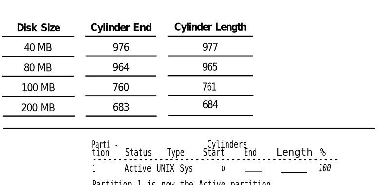
6-16-1. Disk Size in Cylinders 6-5
6-2. Disk Cylinders End and Length 6-6
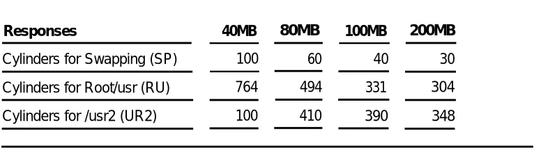
6-3. Cylinders for Filesystems 6-3
8
Troubleshooting
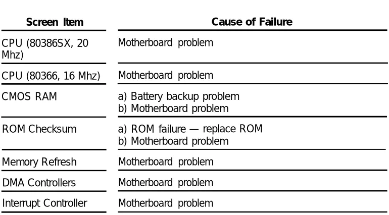
8-18-1. Power On Self-Test Failures 8-1
2
Hardware Setup
2-1. Integrated Solution II Maintenance 2-2. Technician Maintenance Menu 2-3. Display Installed Applications 2-4. Password Protection
2-5. Change/Add or Delete Password 2-6. Maintenance Log
2-7. Parallel Printer Port Setup
2-1 2-17 2-18 2-19 2-20 2-21 2-22 2-27
3
Maintaining IS-II
3-1. Technician Maintenance Menu 3-2. Maintenance Log Menu
3-1 3-2 3-4
4
Maintaining IS-II Applications
4-1. Integrated Solution II Maintenance 4-2. Technician Maintenance
4-3. Administer Integrated Solution Menu
4-1 4-2 4-3 4-4
5
Customizing Applications
5-1. Call Record Collection Information Screen 5-2. Voice System Administration Menu
5-1 5-6 5-9
6
Recovering From Catastrophic Failures
6-1. Administer Integrated Solution II 6-2. Restore Files Menu
7
Upgrading to a New IS-II Release
7-1 7-1. MERLIN LEGEND Integrated Solution II Maintenance Menu 7-2 7-2. Technician Maintenance Menu 7-3 7-3. Administer Integrated Solution Menu 7-4 7-4. Administer IS-II Menu 7-88
Troubleshooting
8-18-1. Maintenance Log 8-5
1
General
This guide is designed to assist AT&T field technicians and your AT&T-authorized dealer responsible for installing and maintaining IS-II. It provides procedures for connecting major system components, customizing applications (if necessary), adding application packages, recovering from catastrophic failure, and troubleshooting.
The MERLIN LEGEND™ Communications System, Integrated Solution II (IS-II), Release 1 consists of a Master Controller II (or II+) processor that is delivered to the customer with the UNIX® System V/386 Release 32-2 operating system, the IS-II Platform Software, the application packages ordered by the customer, and the appropriate expansion boards already installed. You will, however, need to know how to install the-system software in case the customer's system experiences a hard disk crash, or if a customer purchases an application to be installed after delivery of the Master Controller Il.
NOTE:
The IS-II Platform Software is an “umbrella” program for the following software packages:
■ System Programming & Maintenance Utility (SPM) ■ Call Accounting System (CAS)
■ AUDIX™ Voice Power (AVP) ■ Automated Attendant (AA)
The IS-II Platform Software is designed to:
■ Assist with the installation, upgrade, and customization of IS-II applications. ■ Provide a single window for an end-user to access each application package
and any user-specific maintenance items.
■ Provide a single window for a Systems Technician to access each application package, user-specific maintenance items, and Systems Technician-specific maintenance items.
System Configuration
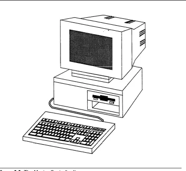
The Master Controller II has main components consisting of the system module, the video display, the keyboard, and an optional tape drive.
Figure 1-1. The Master Controller II
■ 16 MHz 80386SX CPU
NOTE:
For the Master Controller II+, the CPU is 20 MHz.
■ 40MB, 80MB, or 200MB hard disk
NOTE:
■
For the Master Controller II+, a 100MB hard disk is also an option.
1.44MB diskette drive
2MB of onboard system RAM (Random Access Memory) that can be expanded to 4MB
An integral VGA (video graphics adapter) video display controller with
■
■
enhanced 800 x 600 graphics and 132-column text modes The Master Controller II also provides these additional features:
■ One internal speaker interface ■
■
AT intelligent fixed-disk interface with a built-in hard disk controller One real-time clock/calendar CMOS (complementary metal oxide semiconductor) chip with battery backup
Four expansion slots
128-Kbyte ROM (read-only memory) BIOS
Two built-in serial ports and one printer (parallel) port
■ ■ ■
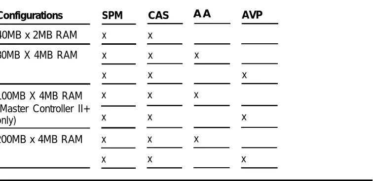
Table I-1. Configurations and Applications
Configurations SPM CAS A A
40MB x 2MB RAM
AVP
x x
80MB X 4MB RAM x x x
100MB X 4MB RAM (Master Controller II+ only)
x x x 200MB x 4MB RAM x
x x
x x
x x
x x
x x x
NOTE:
Using this Guide
Chapter 1- Introduction
This chapter offers an overview of the Integrated Solution II (IS-II) including basic components and software applications supported.
Chapter 2- Hardware Setup
This chapter details system components as originally shipped, materials required for getting the system started, how to make connections to the MERLIN LEGEND Communications System, and what is required if additional applications are to be installed.
Chapter 3- Maintaining IS-II
This chapter describes the contents of the Technician Maintenance Menu and directs you to full information on each menu choice.
Chapter 4- Maintaining IS-II Applications
This chapter explains how to install each application package, either as a new add-on or as part of reinstallatiadd-on after a complete system failure. It also explains how to remove applications.
Chapter 5- Customizing Applications
This chapter describes how to customize Call Accounting System, AUDIX Voice Power, and Automated Attendant based on information provided by the customer.
Chapter 6- Recovering from Catastrophic Failure
Chapter 7- Upgrading to a New IS-II Release
This chapter describes how to upgrade hardware and software to a new release.
Chapter 8- Troubleshooting
Conventions Used in this Guide
The following conventions are used in this guide:
■ ■
■
■
■
Commands and text you should type appear in this style of type.
Values, instructions, and prompts that appear on the screen are in this style of type.
Key names that are always located in the same place on the PC keyboard appear in boxes, as in [ENTER]
Key combinations (holding down one key while pressing another key) are connected with hyphens; for example [CTRL] — [ALT] — [DEL]
2
Preparing for Setup
IS-II is pre-loaded with all of the software applications when shipped from AT&T. Even though all of the software is loaded, the customer will receive a copy of the software on diskettes to use in case of catastrophic failure.
This chapter includes the following information on setting up the system: ■ Preparation
■ Required tools and equipment
■ Specific procedures for setting up, connecting, and checking the system
Selecting a Site for the System
The Master Controller II (or II+) can be used in a variety of environments.
NOTE:
References to the Master Controller II apply to the Master Controller II+ as well. Any information that differs between the two processors will be noted specifically for the Master Controller II+.
CAUTION:
Inform your customer that the Master Controller II needs to be located in an area that meets all of the following requirements:
■ Connected to a grounded power outlet. Nongrounded machines maybe
harmed by static electricity, may fail to work properly, and can be a safety hazard. lmproper program execution, unreadable disks, and extensive machine damage can result.
■ Clean and dust free. Airborne dust, dirt, and smoke can cause excessive wear on the disks and read/write errors.
■ Well-ventilated and away from heat sources. Excessive heat and direct sunlight can cause undesirable conditions such as low-humidity, which can cause static problems.
■ Isolated from strong electromagnetic fields produced by electrical devices (for example, air conditioners, large fans, large electric motors, radio and
television transmitters, and high-frequency security devices).
■ Away from water and excessive humidity.
■ Within 50 feet of the telephone switch (central unit) sharing the same green
wire ground.
— Use two Asynchronous Data Units (ADUs) to connect the Master
Controller II to the MERLIN LEGEND Communications System if they are more than 50 feet apart or if they are not connected to the same circuit as the MERLIN LEGEND Communications System.
■ Close to a phone if AUDIX Voice Power or Automated Attendant is to be installed so that Automated Attendant can be administered.
Installation Tools
Before you start, make sure you have the proper tools ready ■ 3/16“ flat-blade screwdriver
■ #1 Phillips® head screwdriver ■ Pen or penal
■ 3/16“ nutdriver
Hardware Setup
When you have selected the proper site, gathered all required tools, and checked the components, you are ready to setup the system. To prevent damage from electrostatic discharge, remember to take precautions in handling, packing, and storing circuit packs; and remember to ground yourself.
Setup Checklist
The system should be set up in the following order: 1. 2. 3. 4. 5. 6. 7. 8. 9. 10. 11. 12. 13. 14. 15. 16. 17. 18. 19. 20. 21.
Verify that all equipment components were shipped. Connect the video display.
Connect the keyboard.
Prepare the printer (if one is being used). Connect the printer (if applicable). initialize the printer (if applicable). Install IVP4 boards (if applicable). Connect tip/ring to IVP4 boards.
Supply power to the Master Controller Il. Start the system.
Perform the Power On Self Test (POST). Log onto IS-II.
Make sure that proper software packages are installed. Add, change, or delete passwords (if applicable). Change the monitor type (if applicable).
Connect TTY ports. Check TTY connections.
Change printer setup (if applicable). Test the printer.
Verification of Equipment
Verify that all ordered and shipped equipment is on the premises and not damaged in anyway. Unpack the system components from the boxes and make sure they are in good condition. Check for the following:
■ Master Controller II system module ■ Two keys for system module chassis lock ■ System module power cord
■ Video display and cables ■ Keyboard and cable
■ Mounting rails for additional magnetic devices
NOTE:
Mounting rails are optional for the Master Controller II+.
■ Starter kit
■ Equipment Log form
Check the system module, video display, and keyboard. Make sure all associated cables and power cords are present, and if IVP4 boards are included, verify that the correct number have been installed. Store unused magnetic device mounting rails in a secure place for later use in Master Controller II upgrades. A set of matching keys is provided with the system module to operate the mechanical chassis lock. (Tell your customer to keep the keys in a secure place.)
Connecting the Video Display
To connect the video display
1. Connect the video display cable between the connector on the system module and the video display. If you need more connection details, refer to the video display manual that came with the component
2. Attach the video-display power cord to the power socket on the back of the video display. Then connect it to the outlet on the system module (or external power outlet for the Master Controller II+, which does not have an outlet on the system module).
The outlet on the Master controller II (not the II+) is controlled by the system module power switch, which allows you to power up the system module and video display from a single switch.
N O T E :
The color monitor has a detached power cord that must be plugged into the monitor and PC. The attached power cord for the monochrome monitor must be plugged into the PC.
WARNING:
If your monitor has a power switch, do not turn it on at this time.
3. Tighten the screws on all connections.
Connecting the Keyboard
Connect the keyboard by inserting the keyboard cable connector into the socket on the rear of the system module. A label on the back of the Master Controller II
indicates which of the two sockets to use. (Be sure the keyway faces up.)
NOTE:
The socket for the keyboard connector is on the side of the Master Controller II+.
Preparing the Printer
The printers that are supported by IS-II are AT&T 570/571 (dot matrix printer with Centronics-type parallel interface) and the AT&T Models 473 and 474
570/571 Printer
Do not connect the printer cable to the Master Controller II yet. 1.
2. 3. 4.
5.
6.
Unpack the printer and insert the ribbon according to instructions that were boxed with your printer.
Connect the power cable from the back of the printer to an AC outlet. Turn on the printer power switch.
Follow the procedures detailed in section 3.2 of the AT&T 570/571 Printer
User's Guide.
Administer the printer according to section 7.2.1 of the AT&T 570/571 Printer
User’s Guide.
Turn off the printer power switch.
Testing the 570/571 Printer
CAUTION:
Do not run this test until after the ribbon cassette and paper are installed.
1. Connect the AC power cord.
2. Turn the power on while pressing the Form Feed switch on the operation panel.
3. The self-test pattern appears.
473/474 Printer
Do not connect the printer cable to the Master Controller II yet.
1. Connect the power cable from the back of the printer to an AC outlet. 2. Turn on the printer power switch.
3. Follow the procedures detailed in the instructions that came with the printer on setting the printer up.
Testing the 473/474 Printer
CAUTION:
Do not run this test until after the ribbon cassette and paper are installed
Test the printer using the self-test procedure. 1.
2.
3. 4. 5. 6.
Connect the AC power cord and switch the power on. Be sure the printhead is returned to the “home” position at the far left of the platen. Shut the power off. Press and hold down the Form Feed switch located on the far right of the front panel.
Switch the power on.
Release the Form Feed switch.
The “Self-Test Printout” should be generated.
Shut the printer off to stop the Self-Test. If you do not receive the printout, retry the procedure.
Connecting the Printer
to the Master Controller II
You are now ready to connect the printer to the Master Controller Il. Connect the interface cable as follows:
1. Plug the connector of the cable into the printer’s interface outlet and push the two spring clips into position to hold the connector in place.
— Make sure you have the printer interface cable, made especially for the Master Controller II printer connection. (See Appendix A, “Ordering Information.”)
Initializing the 570/571 Printer
- UNIX System Operation
The connection is always made to the parallel port of the computer. To initialize the printer and UNIX system operation, perform the following steps:
1.
2. 3.
4. 5 . 6.
7.
8.
Press the print-quality and on-line buttons and hold them down; turn the power on and then release the print-quality and on-line buttons.
— This activates and prints the printer’s default options so that you can configure the printer to work with IS-II.
Use the scroll-down portion of the line-feed key to get to the line marked 17. Press the on-line key, release it, press the scroll key, and change to the option CR+LF.
Press the print-quality button and release it.
Use the scroll-down portion of the line-feed key to get to line 28.
The option needed for this line is Type 1. Press the on-line key and the scroll-down portion of the line-feed key to change the option to Type 1.
Press the print-quality key and then the Iine-feed key to scroll down to line 61. Press the on-line key and the scroll-down key to change the option
to resewed.
Once these options have been set, press the print-quality key twice.
IVP4 Board Configuration and Installation
Voice applications may have up to three IVP4 boards. If the system has been shipped with the IVP4 boards installed, skip to the section “Supplying Power to the Master Controller Il.”
Figure 2-1. Location of Switches on IVP4 Board .
Identifying the IVP4 Board Configuration
There are three versions of the IVP4 board that differ only in the type of switches used. To properly set the switches, you must identify which configuration is used on the board.
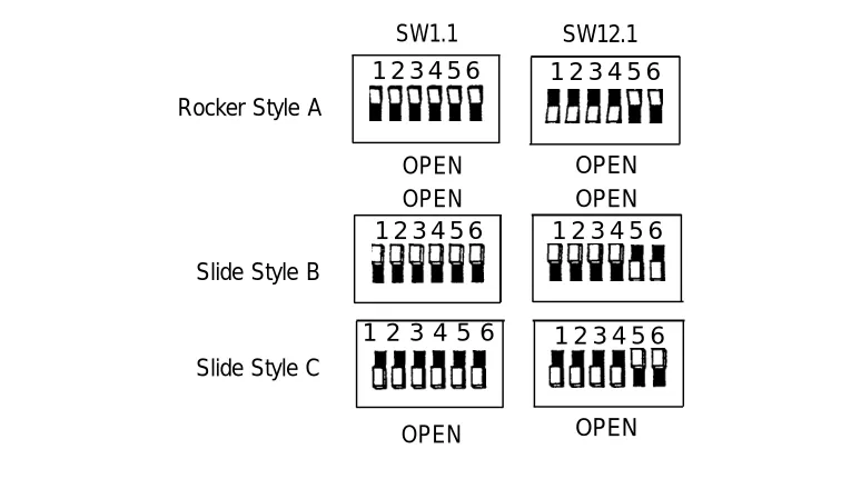
Configuration of New Boards
If your IVP4 board is new and is still packed in the factory box, take note of the type of switch and the factory switch settings. The board should be shipped from the factory with the switches correctly set for use as board 1.
Confirm that the board is appropriately configured:
■ If the board has rocker switches, it is always configuration A as shown in Figure 2-2.
■ If the board has slide switches, it will have one of the configurations (B or C) shown in Figure 2-2.
SW1.1 SW12.1 1 2 3 4 5 6
Rocker Style A
1 2 3 4 5 6
OPEN OPEN
OPEN OPEN 1 2 3 4 5 6
Slide Style B
1 2 3 4 5 6
1 2 3 4 5 6 Slide Style C
1 2 3 4 5 6
OPEN OPEN
Figure 2-2. Factory Switch Configuration
Configuration of Previously Installed Boards
For boards that are already in use, examine the second bank of switches (SW12.1): ■
■
If the board has rocker switches, the configuration is A.
If the board has slide switches that are marked “OPEN” on the top or bottom (or on the side with an arrow toward the top or bottom), the configuration is B (top) or C (bottom) respectively.
If the board has unmarked slide switches, the setting of the second switch (SW12.1) should correspond to one of the settings shown in Figure 2-4. Use the configuration letter at the top of the column in which the match is found. If you are unable to determine the correct configuration by examining the ■
■
switch settings, you will have to test the board as described later in this section to determine the correct configuration.
Mark the board with the corresponding configuration letter (A, B, or C) for reference in resetting the switches.
Setting Switch SW1.1
SW1.1 1 2 3 4 5 6 Rocker Style A
OPEN OPEN 1 2 3 4 5 6
Slide Style B
1 2 3 4 5 6 Slide Style C
OPEN
Figure 2-3. Settings for SW1.1
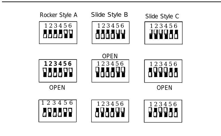
Setting Switch SW12.1
The second switch (SW12.1) sets the board address. Figure 2-4 shows the correct settings for each of the three configurations.
Rocker Style A Slide Style B 1 2 3 4 5 6
1 2 3 4 5 6
1 2 3 4 5 6
OPEN 1 2 3 4 5 6
OPEN
1 2 3 4 5 6 1 2 3 4 5 6
Slide Style C 1 2 3 4 5 6
1 2 3 4 5 6
OPEN
1 2 3 4 5 6
Determining the IVP4 Board Configuration by Testing
If the board has slide switches, it maybe necessary to test the board to determine if it has configuration B or C. If you already know the configuration, use the test in the next section to confirm board operation.
To determine the configuration by testing:
1. Set the switches to match configuration B in Figure 2-2. 2. Install the board and close the case.
3. Install the voice application software if it is not already installed. See Chapter 4 in this guide.
4. All application software that uses the IVP System Software will have a “System Monitor” function available. Open the System Monitor window and examine the Service Status column. If the Service Status is blank, or if the System Monitor window shows no fields at all, the board is either defective or has the other configuration.
NOTE:
If channels 0-3 are populated, the first board is configured property. If channels 4-7 are populated, the second board is configured properly. channels 6-11 are populated, the third board is configured properly.
5. Open the case and change the switches to match configuration C in Figure 2-2. (Be sure to do a shutdown first and then reboot.)
6. Test again. If the board is still not recognized, contact the next tier of AT&T Services support
Testing the IVP4 Switch Settings
If you know the board configuration, set the switches on each board correctly and then perform this test to verify the correctness of the switch settings.
1.
2. 3.
4.
Set the switches for each board according to its configuration and board number. See Figure 2-3 and Figure 2-4.
Install the board(s) and close the case.
Install the voice application software if it is not already installed. See Chapter 4 in this guide.
All application software that uses the IVP System Software will have a “System Monitor” function available. Open the System Monitor window and examine the Service Status column. If the Service Status is blank, or if the
If
5. Check the configuration and switch settings and test again. If the board is still not recognized, contact the next tier of AT&T Services support.
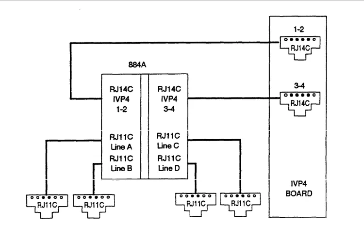
Connecting the IVP4 Voice Lines
Voice lines must be connected to the IVP4 boards. Each IVP4 board has two 6-position modular jacks. Each of these modular jacks is used to connect two voice lines in the RJ14C configuration. The top jack is used for line pairs 1 and 2. The bottom jack is for line pairs 3 and 4.
If the line pairs are run two per jack (RJ14C), use two standard, 4-conductor modular cables. If the line pairs are run individually (RJ11C), a type 884A adapter maybe used to consolidate the four individual fine pairs into two pairs (RJ14C) in each of two cables. (See Figure 2-5.)
WARNING:
There is a magnet on the back of the 884A adapter. Be sure that you do not place this near the hard disk drive or floppy diskettes.
Supplying Power to the Master Controller II
CAUTION:
Before doing anything else, make sure that the voltage and the frequency of the wall power outlet are identical to those specified on the sticker affixed to the back panel of the system.
The standard power cord supplied with the system is detachable and plugs into the input power connector at the rear of the chassis. The input end terminates in a standard 3-prong plug for 115 VAC operation. Do not change the line voltage select switch that is set for 115 VAC.
DANGER:
You must use a 3-prong grounded plug to eliminate the danger of shock. If you use an extension cable, take the safety precaution to make sure it has a 3-prong grounded plug, and is no longer than 6 fret.
1. Be sure the power is OFF and the voltage select switch is preset for 115 VAC operation.
2. Connect the female end of the power cord to the connector at the rear of the system module.
3. Connect the male end to an AC power source.
Starting the System
1. Remove the drive protection card from the diskette drive. 2. If you have a color monitor, turn it on.
3. Press the system-module power switch to the ON position.
Performing the Power On Self-Test (POST)
Each time the system is turned on or reset, POST runs automatically and checks the CPU, keyboard, video display, memory, and most built-in peripheral devices.
Depending on the amount of extended memory installed, the memory test takes 3 to 15 seconds to complete. During a soft boot (pressing the [CTRL] — [ALT] — [DEL] keys at
the same time), the system executes all POST tests except memory.
CAUTION:
Do not perform the [CTRL] — [ALT] — [DEL] soft boot unless you are prompted to do so.
When POST is completed, the system beeps once. A display similar to the following will appear. If the status of any item is FAIL , refer to the following documentation:
■ Chapter 8 “Troubleshooting”
■ AT&T 6366/SX Work Group System User’s Guide
■ AT&T Applications Controller User’s Guide (for the Master Controller II+)
NOTE:
Phoenix 80386 ROM BIOS PLUS Version X.XX xx EOB Copyright (c) 1985-1989
Phoenix Technologies Ltd. All rights Reserved
Resident Diagnostics PASS
CPU (i80386SX, 16 MHz) PASS
CMOS RAM PASS
ROM Checksum PASS
Memory Refresh PASS
DMA Controllers PASS
Interrupt Controller PASS
Keyboard PASS
Dedicated Memory 384 Kbyte
Base Memory
Extended Memory
Total Memory
Clock/Calendar
Floppy Disks
Hard Disks
640 Kbyte
3072 Kbyte
4096 Kbyte
PASS
1 Present
1 Present
Primary Boot-strap
NOTE:
Extended Memory will indicate 1024 Kbyte if you have a 40MB controller with 2MB of RAM.
Logging Onto IS-II
1. At the Login: prompt type maint and then press [ENTER] .
2. At the Password: prompt, type the password and then press [ENTER] .
— The Integrated Solution II Maintenance window is displayed showing all the applications that are installed.
Integrated Solution II Maintenance AUDIX Voice Power (AVP)
Call Accounting System (CAS)
System Programming and Maintenance Utility (SPM) >Technician Maintenance
Exit.
HELP
Checking Application Packages
1. After you have logged on and the Integrated Solution II Maintenance menu appears, move the cursor to Technician Maintenance and then press
[ENTER] .
NOTE:
To select any item in a menu, you can use the arrow keys to move the cursor or type the first few characters of the menu item until the cursor moves to it. For any additional information on screen navigation, see “Screen Navigation” in Chapter 2 of the AT&T Integrated Solution II
System Manager's Guide.
— The Technician Maintenance window is displayed.
Technician Maintenance
>Administer Integrated Solution Backup Files
Restore Files Maintenance Log Printer Setup Password Protection Set Time and Date System Shutdown Full Screen UNIX
Voice System Administration
HELP CANCEL
Screen 2-2. Technician Maintenance Menu
2. Move the cursor to Maintenance Log and press [ENTER] .
3. Select Display Installed Applications.
— The list should include all installed application packages. If there are more applications than fit in the window, press [F3] (Next Page) to
display the next window.
— If any of the essential software necessary to run Integrated Solution II (or the ordered applications) do not display on the screen, the software has not been installed properly.
Essential software consists of:
■ MERLIN LEGEND Integrated Solution II Platform Software ■ MERLIN LEGEND System Programming & Maintenance Utility ■ Editing Package
■ FACE HELP ■ F A C E ■ FMLI
Display Installation Applications
MERLIN LEGEND System Programming & Maintenance Utility Version x AUDIX Voice Power Applicaiton Software Rx
MERLIN LEGEND Switch Integration Software Release x Integrated Voice Power System Software x
Cartridge Tape Utilities- Version x Editing Package - Version x
FACE HELP Version FACE Version x FMLI Version x
MERLIN LEGEND Integrated Solution II Platform Software Release x MERLIN LEGEND Call Accounting System x
MERLIN LEGEND Automated Attendant SoftwareRelease x
PREV PAGE NEXT PAGE CANCEL
NOTE:
The “x” following the applications listed on the menu represents the release number of the software. Your display will contain the actual release number of the applications installed on
the system.
4. To exit, back out of the menus by using the [F6] (CANCEL) function key.
Adding, Changing, or Deleting Passwords
Although you can add, change, or delete passwords for any application, it is absolutely essential that you do not do so unless the customer has requested it. (This does not affect the maint password. )
1. Select Password protection from the Technician Maintenance window and press [ENTER] .
— The Password Protection window is displayed.
NOTE:
This window will display all installed applications.
Password Protection
>AUDIX Voice Power (AVP)
Call Accounting Software (CAS) IS II User Login (is)
System Programming & Maintenance Utility (SPM)
HELP CANCEL
2. Select the item you want and then press [ENTER] .
— The Change/Add or Delete Password window is displayed.
Change/Add or Delete Password >Change/Add
Delete
HELP CANCEL
Screen 2-5. Change/Add or Delete Password
Changing the Password
1. 2.
3. 4.
To change the password, select Change/Add and then press [ENTER] .
When you see the first message below, enter the new password and press
[ENTER] , then re-enter it at the next prompt and press [ENTER] again.
New Password:
Re-enter new password:
The password has been changed Strike ENTER when ready.
— When you have completed this, you are notified that the password has
been changed.
Press [ENTER] to return to the Password Protection window.
If you are finished, press [F6] (CANCEL) to return to the Technician
Maintenance window. Otherwise, you can continue to make changes. — The change will take effect when the user exits the Main menu and
Deleting a Password
1. To delete a password, select Delete and press [ENTER] .
— The system responds:
The password has been deleted Strike ENTER when ready
2. Press [ENTER] to return to the Password Protection window.
3. Press [F6] (CANCEL) to return to the Technician Maintenance window.
Changing the Monitor Type
The system is already set up (defaulted) to be used with a monochrome monitor. Use this feature if a color monitor has been connected to the system.
1. Select Maintenance Log from the Technician Maintenance menu and then press [ENTER] .
— The Maintenance Log window is displayed.
Maintenance Log
>Change Monitor Type
Display Installed Applications IVP Board Diagnostics
TTY Check Printer Test Disk Usage Report
HELP CANCEL
NOTE:
IVP Board Diagnostics will only appear if AUDIX Voice Power or the Automated Attendant is installed.
2. Select Change Monitor Type, and then press [ENTER]
— The window allows you to select etiher color or monochrome. 3. Select Color, and then press [ENTER].
— The system displays confirmation messages. 4. Press [ENTER] to return to the Maintenance Log window.
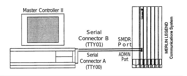
Connecting TTY Ports
The Master Controller II communicates with the MERLIN LEGEND Communications System call processor through the system module TTY ports. Serial Connector A (TTY00) is used for administering the MERLIN LEGEND Communications System while Serial Connector B (TTY01) is used for the Call Accounting System.
This procedure describes how to interconnect the Master Controller II and the MERLIN LEGEND Communications System.
Connecting the IS-II Hardware
Connect the system module and the MERLIN LEGEND Communications System as follows:
1.
2.
3.
4.
Attach a 355AF adapter to Serial Connector A (TTY00) of the Master Controller Il.
Attach a 9-pin-to-25-pin converter to Serial Connector B (TTY 01) of the Master Controller Il.
Attach a 355AF adapter to the 9-pin-to-25-pin converter on Serial Connector B.
Connect a D8W-87 cord between the 355AF adapter and SMDR port of the MERLIN LEGEND Communications System call processor. (If the distance exceeds 50 feet or if the Master Controller II and the MERLIN LEGEND Communications System do not share the same outlet, refer to the Note following these instructions.)
NOTE:
If the MERLIN LEGEND Communications System is located at a distance greater than 50 feet from the Master Controller II, DB25 cables from the MERLIN LEGEND Communications System Admin port and the SMDR port will have to be extended with Z3A2 ADU cable drivers. Two Z3A2 ADU interface units are required for each cable, one at each end. Refer to Chapter 3 of the AT&T MERLIN LEGEND™ Communications System Installation,
Master Controller II
Serial Connector B
(TTY01)
SMDR P o r t Serial ADMIN Connector A Port
(TTY00)
Testing TTY Ports
To determine whether the TTY ports are connected, follow this procedure. 1. From the Integrated Solution II Maintenance Menu, select Technician
Maintenance and press [ENTER].
— The Technician Maintenance window appears. 2. Select Maintenance Log and press [ENTER].
— The Maintenance Log window appears. 3. Select TTY Check and press [ENTER] .
— If a message appears that the ports are not connected, check the
physical connections, cables, and connectors.
Changing the Printer Setup
NOTE:
Skip this section if the system is using the AT&T 570 printer.
This option allows you to change the default printer type from ATT570 and indicate whether a filter should be used. Refer to the “Printer Operation” section of the UNIX
3.2.2 System Operations Guide for information on when you should not use the fitter.
In any case, we recommend that you keep the setting for this as yes.
1 . Select Printer Setup from the Technician Maintenance menu, and then press [ENTER].
Parallel Printer Port Setup Port Number: 01 (/dev/lp) Device Currently on Port: Printer Printer Type: AT&T570
Printer Name: islpr
Should Filter be used: No
HELP CHOICE SAVE CANCEL
Screen 2-7. Parallel Printer Port Setup
2. Press the [F2] (CHOICES) function key to display the list of
available printers.
3. Use the arrow keys to make your selection; then press [ENTER] .
4. Press [F3] (SAVE) to save the information you entered.
— The screen displays your selection and asks for confirmation. 5. Press [F3] (CONT) if it is correct or [F6] (CANCEL) if not
6. Press [F3] (CONT) to return to the Technician Maintenance window.
Testing the Printer
This option submits a job to the printer so that you can verify the connections.
NOTE:
To run the Printer Test, do the following from the Maintenance Log:
1. Select Printer Test from the Maintenance Log window and press [ENTER] .
— The Confirm Printer Test window is displayed.
— The system informs you that the current printer configuration defaults are being written to the printer.
— If the printer test fails, first check to see that the printer is powered, ready, and has paper. Next check the printer cable for proper connections. Should the fault persist, substitute the cable and printer with known good units to determine the faulty component.
2. Press [F3] (CONT) to get the job output
3. Press [F6] (CANCEL) to return to the Maintenance Log window.
Running IVP Diagnostics
Diagnostics for the IVP4 boards should be run during and after initial setup to determine whether everything is connected properly and there is dial tone. To diagnose the IVP board, do the following:
1. Select IVP Board Diagnostics from the Maintenance Log window and then press [ENTER] .
— The system searches for loop current and dial tones on the
administered boards and then informs you if the IVP board passes the test. If dial tone is not found, check the Tip/Ring connections. Also check the positions of the SW1.1 and SW12.1 switches on the board against those shown in “IVP4 Board Configuration and Installation” in this chapter. Insure that the IVP4 board is properly seated in the motherboard connector.
If the failure persists, you will have to replace the board.
NOTE:
If the IVP board is not present, the system responds: Can’t Diagnose Card x, It is not present.
(The “x” indicates the board location number, which will be 0, 1, or 2.)
Customizing the System
When you have completed all of the procedures in this chapter, and all ordered application packages are included, some of the software applications must be customized before they can be administered on the system. This information is contained in Chapter 5, “Customizing Applications”.
It may be necessary for you to add software applications to the system if they were ordered after the system was already configured. If this is the case, refer to
3
Technician Maintenance Menu
The Technician Maintenance menu allows you to perform maintenance functions for IS-II Platform Software and applications.
A screen similar to the following appears:
Technician Maintenance
>Administer Integrated Solution II Backup Files
Restore Files Maintenance Log Printer Setup Password Protection Set Time and Date System Shutdown Full Screen UNIX
Voice System Administration
HELP CANCEL
Screen 3-1. Technician Maintenance Menu
Each of these options is briefly described under the sections in this chapter with references to more detailed explanations.
NOTE:
Voice System Administration will appear only if a voice system is installed.
Administering Integrated Solution II
Backing Up Files
File backups should be conducted regularly by the IS-II system manager. Refer to the AT&T Integrated Solution II System Manager's Guide, Chapter 5, for procedures on how to back up the system.
NOTE:
It is suggested that prior to backing up IS-II files, the system manager back up the telephone switch system programming information to the hard disk via SPM. If this is done, IS-II will back up the system programming information contained in the SPM directories along with the IS-II file information. See Chapter 2 of the AT&T MERLIN
LEGEND™ Communications System: System Programming Guide for
SPM backup procedures.
Restoring Files
Maintenance Log
The following functions are available through the Maintenance Log.
To perform any of these functions, select Maintenance Log from the Technician Maintenance menu, and press [ENTER] . The Maintenance Log window is displayed.
Maintenance Log
>Change Monitor Type
Display Installed Applications IVP Board Diagnostics
TTY Check Printer Test Disk Usage Report
HELP CANCEL
Screen 3-2. Maintenance Log Menu
Changing Monitor Type
The system is already setup (defaulted) to be used with a monochrome monitor. Use this feature if a color monitor has been connected to the system. See Chapter 2, “Hardware Setup,” for more information.
Displaying Installed Applications
Diagnosing the IVP Board
Diagnostics for the IVP4 boards should be run after the installation of each additional IVP4 board, and whenever problems indicate any possible malfunction of the IVP4 board(s). Refer to Chapter 2, “Hardware Setup,” for more information.
NOTE:
IVP Board Diagnostics appears on the Maintenance Log only if AUDIX Voice Power or Automated Attendant is installed.
Checking TTY Connections
This option allows you to confirm that all TTY ports are connected to the system. See Chapter 2, “Hardware Setup,” for information on TTY connections.
Testing the Printer
You can test for proper printer functions by using this option. However, if you are installing the printer, see the information on testing the printer in Chapter 2 under “Testing the Printer.”
Displaying the Disk Usage Report
The Disk Usage Report provides information on the available disk space for System and Voice partitions. Refer to Chapter 8, ‘Troubleshooting,” for information on how to display and interpret this report.
Setting Up the Printer
You can specify the printer type being used and indicate Whether a filter should be used. Information on setting up the printer can be found in Chapter 2 under “Changing the Printer Setup.”
Adding, Changing, or Deleting Passwords
You can add, change, or delete passwords for the installed applications. For details, see Chapter 2, “Hardware Setup.”
Setting the Time and Date
The time and date set for IS-II must be synchronized with the time and date set for MERLIN LEGEND Communications System. Refer to Chapter 3 in the AT&T
Integrated Solution II System Manager's Guide for information on how to set
Shutting Down the System
To protect the data stored on the hard disk, this procedure must always be
performed before turning off power to the system and before moving the hardware. Refer to Chapter 5 in the AT&T Integrated Solution II System Manager's Guide for information on this option.
Accessing Full Screen UNIX
You will only need to access UNIX in troubleshooting situations under the direction of a tier 3 engineer.
Administering the Voice System
4
Preparing to Install Applications
There are two instances in which you wiII need to install IS-II application software: in the event of a catastrophic failure and when the customer adds an application after initial system purchase. If you are installing an upgraded release of an application that the customer already has, see “Updating IS-II and Applications” in Chapter 7 of this guide.
If you are installing application software after a catastrophic failure, all basic IS-II software must have been reinstalled before you can install any application package. (See Chapter 6.)
If you are simply adding a software application package to an existing system, continue with the instructions in this chapter.
NOTE:
If you attempt to install a package that already exists on the system, an Error Message Screen appears.
2. At the password: prompt, type the password and then press [ENTER] .
— The Integrated Solution II Maintenance window is displayed.
NOTE:
If any applications are already installed, their names will appear on this screen.
Integrated Solution II Maintenance
System Programming and Maintenance Utility (SPM) >Technician Maintenance
Exit
HELP
3. Select Technician Maintenance and then press [ENTER] .
— The Technician Maintenance Window is displayed.
NOTE:
“Voice System Administration” will appear only if a voice system is installed.
Technician Maintenance
>Administer Integrated Solution II Backup Files
Restore Files Maintenance Log Printer Setup Password Protection Set Time and Date System Shutdown Full Screen UNIX
Voice System Administration
CANCEL HELP
4. Select Administer Integrated Solution II and then press [ENTER] .
— The Administer Integrated Solution II window appears.
Administer Integrated Solution II
IS-II Platform Software (ISIIPS)
>System Programming & Maintenance Utility (SPM) AUDIX Voice Power (AVP)
Cartridge Tape Utilities Call Accounting System (CAS) Automated Attendant (AA)
HELP UN/MARK INSTALL UPDATE REMOVE CANCEL
Screen 4-3. Administer Integrated Solution Menu
5. Move the cursor to each application package you are going to install or update (such as SPM or ISIIPS), and press [F2] to mark each application as
you select it
NOTE:
SPM and ISIIPS can only be updated; they cannot be installed or removed.
NOTE:
You can select either AVP or AA, but not both. If you already have one and have selected the other, a note will appear on your screen
indicating that one of the packages is already present
If you marked an application by error, move the cursor back to that application and press [F2] again to undo the selection.
6. When you have finished making your selection(s), press [F3] to begin the
installation procedure.
Installing AUDIX Voice Power
In order to install AUDIX Voice Power, you must first have the IS-II Platform Software installed, which is already installed unless a catastrophic failure has occurred (see Chapter 6, if necessary). Installation consists of five steps, which must be completed in the 1. 2. 3. 4. 5. following order:
Install the Integrated Voice Power (lVP) System software. Install the AUDIX Voice Power (AVP) application software. Install the MERLIN LEGEND Switch Integration software.
Reboot the system (by pressing [ENTER] when prompted) for the changes to
take effect.
Confirm that the installation was successful.
The software you need for installing this application consists of the following: ■
■ ■ When
Integrated Voice Power System software (four diskettes) AUDIX Voice Power application software (five diskettes) MERLIN LEGEND Switch Integration software (one diskette)
you have logged onto the system and marked the AVP application (as described in “Preparing to Install Applications” at the beginning of this chapter), the following messages appear:
Insert first diskette of Integrated Voice Power System Software
Strike ENTER when ready.
You are now ready to install this application.
Step 1: Install IVP System Software
1. Insert diskette #1 and press [ENTER] .
— The screen shows:
Verifying Integrated Voice Power System Software diskette
— If you insert the wrong diskette or forget to put the diskette in, the
system responds: Confirm
Incorrect, missing, or damaged diskette. Please correct.
2.
3.
4.
5.
— When you have the correct diskette inserted, the system responds:
Copying Integrated Voice Power System Software to hard disk
do not remove diskette.
Reached end of medium on input. You may remove this diskette.
Insert diskette number 2 and strike the <ENTER> key.
Remove diskette #1, insert diskette #2, and press [ENTER] .
— When the process is complete, the system responds: Reached end of medium on input.
You may remove this diskette.
Insert diskette number 3 and strike the <ENTER> key.
Remove diskette #2, insert diskette #3, and press [ENTER] .
— When the process incomplete, the system responds: Reached end of medium on input.
You may remove this diskette.
Insert diskette number 4 and strike the <ENTER> key.
Remove diskette #3, insert diskette #4, and press [ENTER] .
— When the process is complete, the screen shows the following: You may now remove the diskette from the drive.
Installing Integrated Voice Power System Software.
. . . .
— A series of dots prints indicating that the files are being moved from a
temporary to a permanent area. Remove the diskette from the drive.
NOTE:
Do not quit at this point.
Step 2: Install AVP Application Software
When the IVP System Software has been completely loaded, you will be prompted to install the AVP application software.
1. Insert the first AVP application software diskette when you see the following message:
Insert first diskette of AUDIX Voice Power Application Software.
2. Press [ENTER]
.
— The following messages display:
Verifying AUDIX Voice Power Application Software diskette.
Copying AUDIX Voice Power Application Software to hard disk do not remove diskette.
Reached end of medium on input. You may remove this diskette.
Insert diskette number 2 and strike the <ENTER> key.
3. Remove diskette #1, insert diskette #2, and then press [ENTER] .
— When the process is complete, the system responds: Reached end of medium on input.
You may remove this diskette.
Insert diskette number 3 and strike the <ENTER> key.
4. Remove diskette #2, insert diskette #3, and then press [ENTER] .
—When the process is complete, the system responds: Reached end of medium on input.
You may remove this diskette.
Insert diskette number 4 and strike the <ENTER> key.
5. Remove diskette #3, insert diskette #4, and then press [ENTER] .
—When the process is complete, the system responds: Reached end of medium on input.
You may remove this diskette.
Insert diskette number 5 and strike the <ENTER> key.
6. Remove diskette #4, insert diskette #5, and then press [ENTER] .
— When the process is complete, the system responds: You may now remove the diskette from the drive.
Installing AUDIX Voice Power Application Software.
. . . .
— A series of dots prints indicating that the files are being moved from a temporary to a permanent area.
NOTE:
If you are not successful in installing the application software, the system responds:
AUDIX Voice Power Application Software installation failed
7. When the software has been loaded successfully, the system will indicate that it is ready for the MERLIN LEGEND Switch Integration Software diskette.
NOTE:
Do not quit at this point.
Step 3: Install MERLIN LEGEND Switch Integration Software
1. Wait for the following message to appear:
Insert first diskette of MERLIN LEGEND Switch Integration Software.
Strike ENTER when ready.
2. Insert the MERLIN LEGEND Switch Integration software diskette and then press [ENTER] .
— The system displays other messages and then copies the switch integration software.
Step 4: Reboot the System
1. Wait until the following message appears. Confirm
To complete the install/remove process a shutdown is now being initiated automatically.
Make sure your diskette drive is empty. If you are installing or removing controller boards, you may power down the system after the shutdown has completed.
Strike ENTER when ready or ESC to stop.
2. Be certain the drive is empty then press [ENTER] .
3. The system continues to send messages; when you see the following message,
The system is down. Reboot the system now.
press [CTRL] —[ALT] — [DEL] or the RESET button. The system gives diagnostic
Step 5: Confirm AVP Installation
When the Iogin prompt appears, you are ready to confirm that the AVP application software has been installed on the Master Controller II.
1. Log into the system using the maint Iogin and the password.
— The IS-II Main Menu should include AUDIX Voice Power as an item. 2. Select Technician Maintenance from the Integrated Solution II
Maintenance window.
3. Select Maintenance Log from this menu. — The Maintenance Log window is displayed. 4. Select Display Installed Applications.
— The list should include
Integrated Voice Power System Software Release x AUDIX Voice Power Application Software Rx MERLIN LEGEND Switch Integration Software Rx
5. To exit, back out of the menus by pressing [F6] (CANCEL).
Installing the Automated Attendant (AA)
To install the Automated Attendant application software, you must first have the IS-II Platform Software installed, which is already installed unless a catastrophic failure has occurred. (See Chapter 6, if necessary.) Installation consists of four steps, which must be followed in this order:
1. Install the Integrated Voice Power (lVP) System software.
2. Install the MERLIN LEGEND Automated Attendant (AA) software.
3. Reboot the system (by pressing [ENTER] when prompted) for the changes to
take effect.
4. Confirm that the installation was successful.
The software you need for installing this application consists of the following: ■ Integrated Voice Power System software (four diskettes)
■ MERLIN LEGEND Automated Attendant application software (four diskettes) When you have logged onto the system and marked the Automated Attendant application (as described in “Preparing to Install Applications” at the beginning of this chapter), the screen shows the following:
Insert first diskette of Integrated Voice Power System Software.
Strike ENTER when ready.
Step 1: Install IVP Software
1. Insert diskette #1 and then press [ENTER] .
— The screen eventually shows the following:
Copying Integrated Voice Power System Software to hard disk
do not remove diskette.
Reached end of diskette on input. You may remove this diskette.
Insert diskette number 2 and strike the <ENTER> key.
2. Remove diskette #1, insert diskette #2, and then press [ENTER] .
3. When prompted, remove diskette #2, insert diskette #3, and then press [ENTER] .
4. When diskette #3 has completed its input, remove it, insert diskette #4, and then press [ENTER] .
— When this diskette is completely loaded, the screen shows the following:
You may now remove the diskette from the drive
Installing Integrated Voice Power System Software
. . . .
— A series of dots prints indicating that the files are being moved from a temporary to a permanent area.
Step 2: Install AA Software
You are ready to install the Automated Attendant (AA) application software when the screen displays
Insert first diskette of Voice Power Automated Attendant.
Strike ENTER when ready.
1. Insert diskette #1, and then press [ENTER] .
— The system responds:
Verifying Voice Power Automated Attendant diskette.
Copying Voice Power Automated Attendant to hard disk
do not remove diskette.
3.
4.
5.
When the system prompts you to remove diskette #2 and insert diskette #3, place the third diskette into the drive and then press [ENTER] .
When the system prompts you to remove diskette #3 and insert diskette #4, place the third diskette into the drive and then press [ENTER] .
When the system prompts you to do so, remove the diskette from the drive.
— You will see the following message:
Installing Voice Power Automated Attendant.
. . .
-— A series of dots prints indicating that the files are being moved from a temporary to a permanent area.
Step
3: Reboot the System
1. Wait until you see this message. Confirm
To complete the install/remove process a shutdown is now being initiated automatically.
Make sure your diskette drive is empty. If you are installing or removing controller boards, you may power down the system after the shutdown has completed.
Strike ENTER when ready or ESC to stop.
2. Be certain that the drive is empty; then press [ENTER] .
3. The system continues to send messages, and when you see the message, The system is down.
Reboot the system now.
press [CTRL] — [ALT] — [DEL] or the RESET button. The system gives diagnostic
Step 4 Confirm AA Installation
When the Iogin prompt appears, you are ready to confirm that the AA application software has been installed on the Master Controller Il.
1.
2.
3.
4.
Log into the system using the maint Iogin and the password.
— The IS-II Main Menu should include Automated Attendant as an item.
Selected Technician Maintenance from the Integrated Solution II Maintenance window.
Select Maintenance Log from this menu. — The Maintenance Log window is displayed. Select Display Installed Applications.
— The list should include
Integrated Voice Power System Software Release x MERLIN LEGEND Automated Attendant Rel x.x
Installing Call Accounting System (CAS)
In order to install the Call Accounting System application, you must first have the IS-II Platform Software installed, which is already installed unless a catastrophic failure has occurred. (See Chapter 6, if necessary.) Installation consists of two steps:
1. Install the Call Accounting System (CAS) software diskettes. 2. Confirm that the installation was successful.
The software you need for installing this application consists of the following: ■ Call Accounting System software (four base diskettes)
■ CAS Setup software (three diskettes, to be used later) .
NOTE:
The three additional diskettes used for completing the CAS application package are designed to be used by an implementor. (Instructions for these diskettes are in Chapter 5 under “CAS Customization”.)
When you have logged onto the system and marked the CAS application (as described in “Preparing to Install Applications” at the beginning of this chapter), the following message appears:
Insert first diskette of Call Accounting System
Strike ENTER when ready.
Step 1: I Install CAS Software
1. Insert diskette #1 and then press [ENTER] .
— The screen shows:
Verifying Call Accounting System Software diskette
— If you insert the wrong diskette or forget to put the diskette in, the system responds:
Confirm
Incorrect, missing, or damaged diskette. Please correct.
Strike ENTER when ready or ESC to stop.
— When you have the correct diskette inserted, the system responds: Copying Call Accounting System Software to hard
disk
do not remove diskette.
Reached end of medium on input. You may remove this diskette.
Insert diskette number 2 and strike the <ENTER> key.
2. Remove diskette #1, insert diskette #2, and then press [ENTER] .
NOTE:
Wait until the floppy indicator light goes out before removing diskettes. When the process is complete, the system responds:
Reached end of medium on input. You may remove this diskette.
Insert diskette number 3 and strike the <ENTER> key.
3. Remove diskette #2, insert diskette #3, and press [ENTER] .
— When the process is complete, the system responds: Reached end of medium on input.
You may remove this diskette.
4. Remove diskette #3, insert diskette #4, and then press [ENTER] .
— When the process is complete, the screen shows the following: You may now remove the diskette from the drive.
Installing Call Accounting System Software.
. . . .
— A series of dots prints indicating that the files are being moved from a
temporary to a permanent area. 5. Remove the diskette from the drive.
Step 2: Confirm CAS Installation
1. Log out and then log back into verify that the main menu includes Call Accounting System as an item.
2. Select Maintenance Log from the Technician Maintenance window. — The Maintenance Log window is displayed.
3. Select Display Installed Applications. — The list should now include
MERLIN LEGEND Call Accounting System x
4. To exit, back out of the menus by pressing [F6] (CANCEL).
There are three CAS setup diskettes to be configured before the application can be used. Information on configuring these diskettes is in Chapter 5 under
‘‘CAS Customization.”
Removing IS-II Applications
Use this function only if the customer has chosen not to continue using an
application or if the customer has had Automated Attendant and is moving to AUDIX Voice Power (in which case, you remove Automated Attendant and install AUDIX Voice Power).
CAUTION:
This procedure destroys all administrative files (and voice files, if any exist) that pertain to the marked application.
NOTE:
Mark the application to be removed then press [F5] (REMOVE) and follow
the instructions.
For AUDIX Voice Power, Automated Attendant, and Cartridge Tape Utilities, a system shutdown is initiated automatically at the end of the removal process. When you are prompted, reboot the system using [CTRL] — [ALT] — [DEL] .
NOTE:
5
CAS Customization
The following description leads you through the CAS user customization process. For more detailed information, see the AT&T Call Accounting System (CAS)
Integrated Solution II Site Installation and Implementation Guide. There are three
setup diskettes to be configured before the application can be used. The CAS User Setup process consists of the following steps:
1. Installing the PBX/KTS Interface 2. Installing the City/State diskette
3. Installing the Major Metro (East or West) or Customized Rate/Tariff diskette 4. Editing the CAS Screens
5. Testing the PBX Interface
Displaying the System Configuration Menu
1. Select Call Accounting System from the Integrated Solution II Maintenance window and press [ENTER] .
— The Call Accounting System menu is displayed. 2. Select System Configuration and press [ENTER] .