518-455-310 September 1991
PARTNER™
II
Communications System
Release 1
Installation and Use
AT&T—Proprietary
This book contains proprietary information of AT&T and is not to be disclosed or used except in
Copyright © 1991 AT&T
AT&T 518-455-310
All Rights Reserved
Issue 1
Printed in U.S.A.
September 1991
Notice
Every effort was made to ensure that the information in this book was complete and accurate at the time of printing. However, information is subject to change.
Federal Communications Commission (FCC) Interference Notice
This equipment has been tested and found to comply with the limits of a Class A digital device, pursuant to Part 15 of FCC rules. These limits are designed to provide reasonable protection against harmful interference when the equipment is operated in a commercial environment. This equipment generates, uses, and can radiate radio frequency energy and, if not installed and used in
accordance with the instruction manual, may cause harmful interference, in which case the user will have to correct the interference at his or her own expense. For additional FCC interference, registration, and repair information, see Appendix D of this book.
Trademarks
PARTNER, MLS-34D, MLS-12D, MLS-12, MLS-6, and SYSTIMAX are trademarks of AT&T. Magic on Hold, MERLIN, and PagePac are registered trademarks of AT&T.
Warranty
AT&T provides a limited warranty to this product. Refer to “AT&T Limited Warranty and Limitation of Liability” in Appendix B of this book.
Ordering Information
The order number for this book is 518-455-310. To order additional books, call 1 800 432-6600 in the U.S. and 1 800 255-1242 in Canada. For more information on how to order this and other system reference materials, see “Reference Materials” in “About This Guide.” For information on ordering replacement parts, accessories, and other compatible equipment, refer to “Product Ordering Information” in Appendix B.
Support Telephone Numbers
AT&T provides a toll-free customer helpline 24 hours a day. In the U.S. call the AT&T Helpline at 1 800 628-2888 if you need assistance when installing, programming, or using your system. In Canada, call one of the following Technical Assistance Centers for service or technical assistance:
Eastern Canada and Ottawa: 1 800 363-1882
Ontario: 1 800 387-4268
Contents
About This Guide
iii1
Overview
1-i■ ■ ■ ■
Managing the System 1-1
Features and Capabilities 1-2
System Components 1-4
Auxiliary Equipment 1-7
2
Installing the Hardware
2-i■ Important Safety Instructions 2-ii
■ Installation Guidelines 2-1
■ An Example System Setup 2-4
■ Installation Procedures 2-6
3
Programming
3-i■ Alphabetical List of Procedures 3-ii
■ Overview 3-1
■ System Programming 3-4
■ Telephone Programming 3-21
4
Using Telephones
4-i■ ■ ■ ■ ■
System Telephones 4-1
Standard Telephones 4-7
Combination Extensions 4-9
Dial-Code Features 4-11
5
Using Auxiliary Equipment
■■ ■ ■ ■ ■ ■
Fax Machines Answering Machines Modems
Automated Attendants Credit Card Scanners
Night Service with Auxiliary Equipment Call Reporting Devices (SMDR)
5-i 5-1 5-6 5-9 5-11 5-12 5-13 5-14
A
Speed Dial Form
A-1B
Maintenance and Customer Support
B-1■ Maintenance B-1
■ In Case of Difficulty B-2
■ Repair Information B-8
■ AT&T Limited Warranty and Limitation of Liability B-8
■ Product Ordering Information B-10
C
Specifications
C-1D
FCC Information
D-1IN
Index
IN-iAbout This Guide
Purpose
PARTNER™ II Installation and Use explains what the PARTNER II
Communications System can do, provides instructions for using the system, and shows you how to get the most out of its many features and capabilities.
How to Use This Guide
■
■
If you are a new user, read Chapters 1, 3, and 4 to familiarize yourself with the system’s features and to learn how to program your phone and handle calls.
If you are installing the system for the first time, we suggest you read Chapters 1 through 3, which will give you an overview of the system components, and instructions for installing and programming them, If you are installing auxiliary devices, also see Chapter 5.
If you are adding equipment to an existing system, see Chapter 2, “Installing the Hardware,” Chapter 3, “Programming,” and Chapter 5, “Using Auxiliary Equipment.”
If you need to reprogram the system or individual extensions, see Chapter 3, “Programming,” or the Programming Quick Reference sections at the back of this book.
Once you are experienced with the system, use the Table of Contents ■
■
■
or Index to locate the information you need.
Product Safety Statements
This book contains several product safety statements, identified by a .
CAUTION:
WARNING:
Indicates the presence of a hazard that can cause severe or fatal personal injury if the hazard is not avoided.
Carefully read the
WARNING
statement on page 2-7. Opening the system modules or backplane will expose you to hazardous voltages, which can cause severe or fatal personal injury. Also, read “Important Safety Instructions” on page 2-ii before performing any installation procedures.Terminology
This guide refers to AT&T telephones specifically designed to work with the PARTNER II system as system phones. System phones include the MLS-34D, MLS-12D, MLS-12, MLS-6, and MLC-6 model telephones. When specific models are discussed, the model numbers are given.
You can also use industry-standard telephones with the system. This guide refers to such telephones as standard phones.
Reference Materials
These reference materials are available to help you install, program, and use the system (the order numbers are in parentheses):
■ Installation and Use (518-455-310) provides instructions for installing,
programming, and using the system.
■ Quick Reference for Use with MLS-Series Telephones (518-455-305,
package of 6) contains basic instructions for using system phones.
■ MLC-6 Cordless Telephone: Installation and Troubleshooting
(999-506-143) explains how to install the MLC-6 cordless telephone and how to solve any difficulties that might occur when using it.
■ MLC-6 Cordless Telephone Quick Reference: Display and Controls
(999-506-146) explains how to use the MLC-6 cordless telephone with your system.
To order the above reference materials, call the AT&T Customer Information Center:
In the U.S.: 1 800 432-6600 In Canada: 1 800 255-1242
In addition, a System Planner (GBS-123) provides the forms needed to plan and record how your system and telephones are to be programmed. You can order the Planner from AT&T Forms Services at 1 800 367-6487.
How to Comment on This Guide
Overview
1
Contents
Managing the System
1-1Features and Capabilities
1-2System Components
■ Control UnitSystem Modules System Capacity ■ Telephones
System Telephones Standard Telephones
Auxiliary Equipment
■ Industry-Standard DevicesLimitations
Connecting and Using Standard Devices ■ Other Devices
Overview
Managing the System
This guide explains everything you need to know about using your
PARTNER™ II Communications System. If you are responsible for managing the system—whether you are a receptionist, an office manager, or the “resident expert” on using it—you will find instructions and advice on the following topics:
■ Installing System Hardware. If your company already has modular jacks for all outside lines and extensions, you may be able to use the existing wiring to install the system hardware and connect telephones to the system yourself (see Chapter 2 for installation instructions). If you prefer to have an AT&T service technician perform the installation and customize your system, call 1 800 247-7000 or call your AT&T authorized dealer.
The system supports a wide variety of auxiliary equipment, including fax machines, modems, answering machines, credit card scanners, automated attendants, and call reporting devices. See Chapter 5 for advice on setting up these devices to work effectively with the system. ■ Customizing the System. You can change your system’s settings easily
to accommodate new or expanding needs. Chapter 3 gives instructions for making whatever changes are needed—from programming the system to recognize newly added telephone lines to programming newly purchased telephones. It will help you decide how to set up your system and telephones to meet your business’s needs and gives detailed programming instructions.
■ Solving Problems. Appendix B provides information on solving problems and ordering additional accessories and equipment. If your system or telephones malfunction, you may be able to solve the problem by following the steps provided in the “Troubleshooting” section of that appendix. If you still need help, call the 24-hour AT&T Helpline at 1 800 628-2888.
Daily Operation. Depending on how your system is set up, you may ■
need to oversee some of the system’s daily operations. For example, if your system is programmed to use the Night Service feature, you will need to turn on Night Service at the end of each day before leaving the office. (See “Using Night Service” in Chapter 4.)
Features and Capabilities
The following list provides an overview of the system’s basic features, along with the additional capabilities that you can get by customizing it:
■
■
■
■
■
■
■
■
■
Provides a maximum capacity of either 24 lines and 24 extensions, or 16 lines and 48 extensions.
Uses interchangeable parts, making the system easy to install, maintain, and upgrade.
Provides each extension with access to multiple lines from one phone. Supports industry-standard touch-tone and rotary telephones.
Supports two extensions (10 and 11) for system programming. Supports up to two Intercom Autodialers at each programming
extension—for dialing and transferring calls to other system extensions with one touch, and for easily seeing which extensions are busy. Lets you connect fax machines, answering machines, modems, and credit card scanners directly to your phone system. Therefore, you do not have to buy extra lines or expensive adapters to connect these devices to the system.
Displays prompts and messages to guide you when programming, making it easy for you to change the way the system and phones are programmed.
Includes the following flexible dialing restrictions and permissions so you can control telephone activity and phone bills:
■ Line Access Restrictions and Outgoing Call Restrictions that restrict the kinds of calls a user can make on outside lines
■ Disallowed Lists that prevent users from dialing certain telephone numbers (such as 900 numbers)
■ Allowed Lists, System Password, Marked System Speed Dial
numbers, and Emergency numbers for overriding dialing restrictions Combines simplicity of use with a wide range of features, including: ■ Speed Dialing
■ ■ ■ ■ ■
Last Number Redial Do Not Disturb Privacy
Hold
Exclusive Hold Transfer
Loudspeaker Paging Call Forwarding Direct Line Pickup ■
■ ■ ■
■ Supports the following groups of extensions for flexibility in directing and answering calls:
■ Calling Groups allow users to ring or page (voice-signal) a group of extensions at once
■ Call Pickup Groups allow users to answer incoming calls ringing at any extension in a group
■ Extension Hunt Groups allow users to ring or page the first available extension in a group
■ Night Service Group prevents unauthorized use of telephones after normal business hours while allowing incoming calls to be answered ■ Allows you to make and answer calls during a power failure (with
standard phones), while retaining programmed settings for up to four days. (An optional Uninterruptible Power Supply, or UPS, is also available to allow full system operation during a power failure.)
■ Supports optional equipment such as doorphones, hotline telephones, automated attendants, paging systems, call reporting devices,
music-on-hold* systems, and extra alerts.
* If you use equipment that rebroadcasts music or other copyrighted materials, you may be required to obtain
System Components
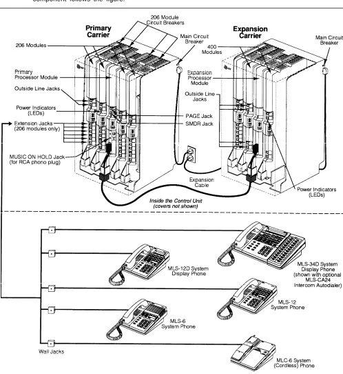
Modular hardware design makes the system easy to install and expand. Figure 1-1 shows the components of the system. A brief description of each
component follows the figure.
Control Unit
The control unit is the heart of the system; it is made up of one or two carriers, which house the system modules. A fully loaded system has two carriers, referred to as the primary carrier and the expansion carrier. Each carrier housing includes a backplane and a cover. All system modules slide into the backplane, which channels power to the system. The cover slides onto the front of the backplane after all the system modules have been installed.
System Modules
The following system modules can be installed in your system: ■
■
Primary Processor Module. The primary processor module provides
the software intelligence that controls the system’s features; it is always installed in the center slot of the primary carrier. It has jacks for a music-on-hold audio source, a loudspeaker paging system, and a call reporting device, such as a printer.
Expansion Processor Module. The expansion processor module
extends the primary processor module’s software capabilities to the lines and extensions located on modules in the expansion carrier; it is always installed in the center slot. An expansion cable connects the primary processor module in the primary carrier to the expansion processor module in the expansion carrier.
206 Module. Each 206 module has jacks to connect a maximum of
two outside telephone lines and six extensions to the system. You can connect telephones and other telecommunications devices (such as fax machines, answering machines, or modems) to the extension jacks on the 206 module (either directly or through your building’s extension jacks). Each 206 module has a green power indicator that shows it is receiving power. The system requires at least one 206 module in the
leftmost slot of the primary carrier.
400 Module. The 400 module is similar to the 206 module, but without ■
■
extension jacks. It has jacks for four outside lines. The module is an inexpensive way to add lines when you do not need more extensions.
(If you are upgrading from a PARTNER or PARTNER Plus System, you can still use its 200 modules, each providing two line jacks.)
System Capacity
The combination of 206 and 400 modules you install in the control unit
determines the number of available lines and extensions. The system will allow up to 24 lines and up to 48 extensions; however, these cannot be achieved simultaneously:
■ For maximum line capacity (24 lines), install four 206 modules and four 400 modules. When maximizing line capacity, you are limited to 24 extensions.
Telephones
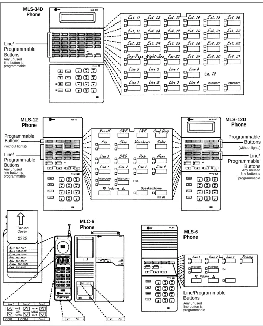
System Telephones
AT&T MLS- and MLC-model telephones are designed to make maximum use of the system’s features. They have several buttons in common: two volume control buttons, two intercom buttons, and the [ Feature ], [ Conf ], [ Transfer ], and
[ Hold ] buttons.
The five system phones and their additional features are: ■
■
AT&T MLS-34D™ Telephone. This phone is the best choice for
extensions 10 and 11—typically the extensions used by the system manager, receptionist, or operator—and for anyone else who makes many outside calls or wants to program many features onto their phones. It has 34 buttons with status lights—two intercom buttons and 32 others that can be used for outside lines, Auto Dial numbers, or programmable features. It also has a built-in speaker and microphone (for dialing and having a conversation without lifting the handset) and a display that shows the following:
■ Current date, day, and time
■ Number dialed and elapsed time (when making a call)
■ Extension number calling you or transferring a call to you (when receiving an inside call)
■ Prompts and messages (when programming the system)
AT&T MLS-12D™ Telephone. This phone has 12 buttons with lights—
two intercom buttons and ten others that can be used for outside lines, Auto Dial numbers, or programmable features. It also has six
programmable buttons without lights, for features that do not require lights (such as Last Number Redial). It has a built-in speaker and microphone, and a display similar to the one on the MLS-34D.
N O T E :
An MLS-34D or MLS-12D is required for system programming. Use the MLS-12D only if there are no MLS-34D phones in the system.
AT&T MLS-12™ Telephone. This telephone has all the features of the
MLS-12D telephone, but without a display.
AT&T MLS-6™ Telephone. This telephone has six buttons with
lights—two intercom buttons and four others that can be used for outside lines, Auto Dial numbers, or programmable features. It also has a built-in speaker but no microphone. This means that a user can dial a number without lifting the handset, but must lift the handset to speak when the party answers.
AT&T MLC-6™ Cordless Telephone. This cordless telephone works
like the MLS-6 corded telephone. It has six buttons—two intercom buttons and four others for outside lines, Auto Dial numbers, or programmable features. It also includes a display that shows line status, an On/Off button that must be pressed before using the phone (to save battery power), and some special cordless feature buttons. ■
■
Standard Telephones
Standard phones are industry-standard (non-proprietary) rotary or touch-tone phones, including feature phones with built-in feature buttons and lights. See “Industry-Standard Devices” in the following section for more information on standard phones.
Auxiliary Equipment
The system works with many telecommunications devices, not only system phones. You can connect industry-standard devices to your system, and certain models of other devices, all without expensive adapters or additional phone lines.
Industry-Standard Devices
Many industry-standard, single-line telecommunications devices will work with the system:
■ Touch-tone, rotary, and cordless telephones (such as those you might have in your home)
■ Fax machines ■ Answering machines ■ Modems
■ Credit card scanners ■ Automated attendants
Limitations
You can connect standard devices to your system, regardless of the manufacturer. The following limitations apply:
■ It must be industry-standard and non-proprietary. That is, it cannot be made specifically for use on a particular telephone system. (For example, you cannot connect an AT&T MERLIN® phone because it is specifically designed for use on a MERLIN system.)
■ Its Ringer Equivalence Number (REN*) cannot be greater than 2.0. (The REN is shown on a label on the device, usually on the bottom.)
NOTE:
You can connect a multiple-line device to the system, but for best results it should be installed and used as if it were a single-line device.
*
Connecting and Using Standard Devices
You can connect a standard device so that it is on an extension by itself, or so that it shares an extension with another piece of equipment (either another standard device or a system phone). An extension with two devices connected to it is called a combination extension. For example, you can connect a
standard touch-tone phone and an answering machine to the same extension. To connect two devices on one extension, you need an inexpensive AT&T 267F2 bridging adapter (two are provided with each 206 module). See Chapter 2 for installation instructions.
For additional information on programming and using fax machines, answering machines, modems, or credit card scanners, see Chapter 5.
Other Devices
You can connect other devices to your system, but only specific models are
compatible with the system. These devices include:
■ MLS-CA24 Intercom Autodialers with Busy Indication allow the users
at extensions 10 and 11 to see which extensions are busy and to automatically dial or transfer calls to them. (The technical names for these features are Busy Lamp Fields [BLF] and Direct Station Select
[DSS]). The system supports up to two AT&T MLS-CA24 Intercom
Autodialers at both programming extensions; each autodialer has buttons for 24 extensions.
■ Call accounting devices and printers allow the system manager to print call reports. The call accounting device or printer connects directly to the primary processor module in the primary carrier. See “Call Reporting Devices (SMDR)” in Chapter 5 for more information.
■ Doorphones allow visitors to ring up to 5 extensions at once by pressing a button on the doorphone; the person who answers a doorphone call can then speak with the visitor at the doorphone. The system supports up to two AT&T PARTNER Plus/II doorphones, which can be installed indoors or outdoors. A doorphone is especially useful for providing access to offices or departments after hours. For example, you can install a doorphone outside your building entrance to allow visitors to ring telephones inside the building when the receptionist is not there and the front door is locked.
■ Loudspeaker paging systems allow you to broadcast a message over a large area, by connecting the paging system directly to the PAGE jack on the primary processor module. The system supports all AT&T paging systems. For information on how to use a loudspeaker paging system with the system, see Chapter 4.
■ Music-on-hold systems allow you to play recorded music to callers
while they are on hold, by connecting the music-on-hold system to the primary processor module. The system supports the AT&T
Magic on Hold® system and most models from other manufacturers. ■ Extra alerts are strobes, lights, chimes, horns, or bells that light or ring
■
■
In-Range Out-of-Building (IROB) protectors are required to prevent
electrical surges from damaging your system when phones are installed in another building, but on the same continuous property. The system supports the AT&T 504A1 IROB protector, which provides coverage over a distance of 3,000 feet for standard phones and 1,000 feet for system phones. (For installation instructions, refer to the booklet packaged with the IROB protector.)
Speakerphones provide hands-free two-way operation of a phone
without lifting the handset. Combining a speakerphone with an MLS-model system phone or a standard phone on an extension in a conference room or office is an inexpensive way for several people at a meeting to conference in other parties. The system supports the AT&T S203 speakerphone. (MLS-model system phones have built-in speakers, but they are designed for individual use—not group—use.)
Repertory dialers allow you to store frequently used numbers for
one-touch dialing. If a user needs many Auto Dial numbers, a repertory dialer can be combined on an extension with a system or standard phone.
Headsets allow users to hold private, hands-free conversations. A
headset is a combination earphone and microphone worn on the head, useful for receptionists, salespeople, or others who need to have their hands free while talking on the phone. AT&T offers several compatible headsets.
Handsets for hard-of-hearing users are designed for those who need ■
■
■
even more amplification than is provided by the volume controls on system phones. Although the volume controls on system phones significantly reduce the need for an amplified handset, hard-of-hearing users may find that the AT&T K6S handset meets their needs.
Installing the Hardware
2
Contents
Important Safety Instructions
Installation Guidelines
Placement of Carriers and Modules ■
■ Line and Extension Numbering
■ Connection of Telephones and Devices Combination Extensions
An Example System Setup
Installation Procedures
■■ ■ ■
Required Parts
Installing the Carriers and Modules Connecting Lines and Extensions Assembling System Phones
Desk Mounting Wall Mounting
Connecting and Testing Telephones
Connecting Paging and Music-on-Hold Devices Connecting MLS-CA24 Intercom Autodialers Replacing a System Module
2-ii 2-1 2-1 2-2 2-2 2-3 2-4 2-6 2-6 2-7 2-8 2-9 2-9 2-9 2-10 2-10 2-11 2-12 ■
Important Safety Instructions
Always follow these basic safety precautions when using the system:
1.
2.
3.
4.
5.
6.
7.
Additional Safety Instructions for
Read and understand all instructions.
Follow all warnings and instructions marked on the product.
DO NOT block or cover the ventilation slots and openings. They prevent the product from overheating. DO NOT place the product in a separate enclosure unless proper ventilation is provided.
Never spill liquid on the product or drop objects into the ventilation slots and openings. Doing so may result in serious damage to the components.
Repair or service must be performed by a qualified repair person.
The product is provided with a three-wire grounding type plug. This is a safety feature. DO NOT defeat the safety purpose of the grounding type plug. DO NOT staple or otherwise attach the AC power supply cord to building surfaces.
DO NOT use the product near water or in a wet or damp place (such as a wet basement).
Installation Personnel
1.
2.
3.
4.
5.
DO NOT install telephone wiring during a lightning storm.
DO NOT install telephone jacks in a wet location unless the jack is specifically designed for wet locations.
Never touch uninsulated telephone wires or terminals, unless the telephone line has been disconnected at the network interface.
Use caution when installing or modifying telephone lines.
The system carriers must be securely wall mounted.
CAUTION:
If any wiring from the extension jacks leaves the building premises, you must install AT&T 504A1 IROB protectors (see Appendix C, “Requirements for Out-of-Building Extensions”).
CAUTION:
Use only AT&T-manufactured PARTNER modules in the PARTNER II
Communications System.
CAUTION:
Environmental and electrical conditions must meet the specifications in Appendix C.
Installing the Hardware
2
This chapter explains how to install the system. It begins with general
guidelines to consider before installation, followed by an example setup. It ends with step-by-step instructions for connecting and testing the components. Follow the instructions that apply to your setup.
IMPORTANT:
Before installation, record your setup choices in the System Planner, available separately.
Installation Guidelines
Placement of Carriers and Modules
■ Carriers. You will be installing either one or two carriers, depending
on the number of lines and extensions you have. If you are going to
install the expansion carrier, plan to install it to the right of the primary carrier, leaving at least six inches of space between the carriers and not more than 24 inches for proper cable connection. Install the
backplane(s) within five feet of a grounded 110 VAC electrical outlet (not controlled by a switch) and the network interface jacks. If installing two carriers, both must be connected to the same power outlet. In addition, when you mount the backplane(s) on the wall, leave at least six inches of clearance at the top and sides, and two feet at the front and bottom. For each carrier, you will need to obtain four #12 screws of the appropriate type for the wall and weight of the carrier (a carrier with four 206 modules and a processor module weighs approximately 27.5 pounds or 12.3 kilograms).
■ System Modules. In the primary carrier, you must install the primary processor module in the center slot and one 206 module in the
leftmost slot. If you are installing the expansion carrier, you must
install the expansion processor module in its center slot. In the
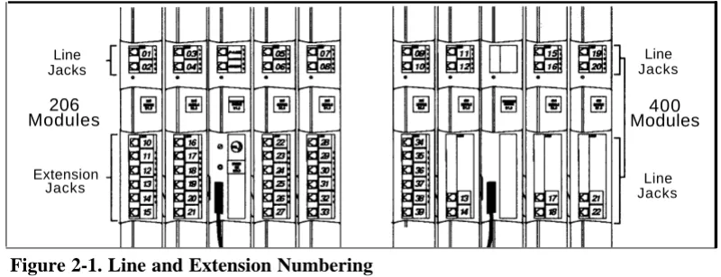
Line and Extension Numbering
Outside lines connect to the top two jacks on 206 modules and any jack on 400 modules. For each 206 module, the system assigns two lines and six
extensions; for each 400 module, the system assigns four lines. The system numbers the lines from 01 through 24 (if you have the maximum number of lines), and numbers the extensions 10 through 57 (if you have the maximum number of extensions).
Figure 2-1 shows line and extension numbering for a system containing both 206 and 400 modules.
Line Jacks
206 Modules
Extension Jacks
Figure 2-1. Line and Extension Numbering
Connection of Telephones and Devices
Line Jacks
400 Modules
Line Jacks
You can connect the following telephones and devices to the system:
■ MLS- and MLC-Model System Phones. System phones require at
least two-pair wiring and are compatible with AT&T 4-pair SYSTIMAX™ wiring. If you need a shorter cord, use AT&T’s two-foot D4BU-29 mounting cord (available separately—see “Product Ordering
Information” in Appendix B). An MLS-34D or MLS-12D is required for system programming at extension 10 or 11. Use an MLS-12D only if there are no MLS-34D phones in the system.
■ MLS-CA24 Intercom Autodialers with Busy Indication. You can connect up to two Intercom Autodialers to each system phone at extensions 10 and 11 (maximum four per system). The Intercom Autodialer has its own power supply, which must be plugged into an AC outlet. (Two autodialers can share one power supply.)
Industry-Standard Devices. Industry-standard devices (including
standard phones) require one-pair mounting cords; AT&T D2R mounting cords are recommended.
■ Standard Phones. Connect standard touch-tone or rotary dial phones to the system for:
– Power Failure Operation. During a power failure, system phones will not work because they require power to operate. However, if standard phones are connected to extensions 10, 16, 22, 28, 34, 40, 46, or 52, they can place and answer outside calls on lines 1, 3, 5, 7, 9, 11, 13, or 15, respectively. Connect a standard phone to one or more of these extensions, either alone or combined with a system phone. (If you combine a standard phone and a system phone on one extension, you may want to turn off the standard phone’s ringer during normal use.)
– Hotlines. A hotline phone must be a standard phone—not a system telephone—but can ring any type of phone. A hotline phone can also be set up to ring the paging system, so announcements can be made over the loudspeaker. Do not connect a Hotline phone to extensions 10, 16, 22, 28, 34, 40, 46, or 52, to keep them available for power failure use.
Auxiliary Equipment. There are a variety of ways to set up fax
machines, modems, answering machines, and automated attendants to work with the system. See Chapter 5 for advice on setting up this equipment. To connect a telephone and a standard device on the same extension, see “Combination Extensions” below.
Doorphones. You can connect up to two doorphones to the system.
Do not connect doorphones to extensions 10, 11, 16, 17, 22, 23, 28, 29, 34, 35, 40, 41, 46, 47, 52, or 53.
Call Reporting Devices. You can connect a call reporting device to
■
■
■
the SMDR jack on the primary processor module for recording call activity. (For more information, see “Call Reporting Devices (SMDR)” in Chapter 5.)
■ In-Range Out-of-Building Protectors. Installing phones in a different
building from the control unit requires AT&T 504A1 In-Range
Out-of-Building (IROB) protectors, to prevent damage due to lightning (installation instructions are included with the protector).
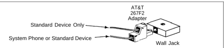
Combination Extensions
You can connect a standard device (such as a standard phone or a fax machine) on an extension by itself, or you can use an AT&T 267F2 bridging adapter (only) to combine the standard device with another standard device or with a system phone at one extension jack. You cannot install two system phones on the same extension, and the combined REN of the two devices on an extension must be no more than 2.0. Figure 2-2 shows how to connect the two devices to the bridging adapter at a combination extension.
AT&T 267F2 Adapter Standard Device Only
System Phone or Standard Device
Wall Jack
An Example System Setup
These two pages show a control unit with two 206 modules and three 400 modules, giving the system a capacity of 16 outside lines and 12 extensions. Although your system will probably differ, this example will give you an idea of the types of equipment you can connect to it. In the example, system phones and industry-standard equipment are connected to ten extensions. The circled numbers in the figure refer to the following list, which gives a brief description of the system’s hardware components.
Control Unit
The control unit shows both the primary and the expansion carriers, plus these components:
■
■
Backplanes. The backplanes channel power to the
system and connect the system modules.
206 Modules. Each 206 module has jacks for two lines
and six extensions.
400 Modules. Each 400 module provides four more line
jacks but no extensions. Notice that the 400 rnodules are installed to the right of the 206 modules.
Primary Processor Module. The primary processor
module contains the software that provides the system’s features. It also has PAGE, SMDR (Station Message Detail Recording), and MUSIC ON HOLD jacks. (See below.)
Expansion Processor Module. The expansion
processor module extends the primary processor module’s software intelligence to the modules in the expansion carrier.
The following auxiliary equipment jacks are on the primary processor module:
■ PAGE. A loudspeaker paging system plugs directly into this modular jack. The system is compatible with any AT&T aging system, including the AT&T PagePac6® shown here.
■ SMDR. A call reporting device connects directly to this jack. AT&T’s 572 serial printer is shown here. ■ MUSIC ON HOLD. AT&T’s Magic on Hold® is
connected to this jack to provide customized music and messages for callers on hold. Other types of audio equipment (including a CD player, cassette player, or stereo receiver) can be connected using an audio cord with an RCA phono plug (not supplied).
Line Jacks. The top two jacks on each 206 module, and
all four jacks on each 400 module, connect to outside telephone lines.
Extension Jacks. The bottom six jacks on each 206
module connect inside wiring for telephones and other telecommunications equipment.
Network Interface Jacks. These jacks provide access
to telephone Iines from the local telephone company. Each outside line was connected to the system by plugging one end of the line cord into one of these jacks, and the other end into a line jack on a 206 or 400 module.
Expansion Cable. The expansion cable connects the
primary processor module to the expansion processor
■
■
module.
Extensions
This example shows various devices—including system phones and industry-standard devices—connected to the modular wall jacks at each extension. (The modular wall jacks connect to the extension jacks in the control unit by way of the building’s inside wiring.)
Extension 10: These devices are connected:
MLS-34D Display Phone. Typically, the receptionist
on extension 10, called the primary programming extension, has an MLS-34D display phone like the one shown here.
MLS-CA24 Intercom Autodialer. An Intercom
Autodialer is connected to the phone for dialing extensions and transferring calls to them with one touch, and for seeing which extensions are busy. (A maximum of four Autodialers—two at extension 10 and two at extension 11—can be connected.)
AT&T 267F2 Bridging Adapter. This adapter permits
the connection of two devices—in this example a standard phone and an MLS-34D phone—on one extension jack. (You cannot connect two system phones.) This is called a combination extension.
Standard Touch-Tone Phone. The MLS-34D phone
on extension 10 will not work during a power failure; therefore, the receptionist can use the standard phone to place and receive calls on line 1.
Extension 11: MLS-34D Display Phone. Another
MLS-34D is connected to extension 11, which is the backup programming extension. This means you can program the system from this extension while the receptionist at extension 10 is free to handle calls.
Extension 12: MLS-12D Display Phone. This display
phone can handle ten outside lines and has a display showing the time, the number dialed, the duration of calls, and programming messages.
Extension 13: Bell. A loud bell is connected directly to
this extension jack.
Extension 14: MLS-12 Phone. This phone is similar to
the MLS-12D phone (see ext. 12), but it has no display.
Extension 15: Doorphone. A doorphone is installed at
the building entrance. When someone at the entrance presses the button on the doorphone, the designated extensions (five maximum) in the office ring automatically.
Extension 16: Standard Phone. A standard touch-tone
phone (such as you might have in your home) is connected directly to the extension jack.
Extension 17: MLC-6 Cordless Phone. An AT&T
MLC-6 cordless phone is connected to this extension. It works like the corded MLS-6 system phone.
Extension 18: Fax Machine and Standard Phone. A
fax machine and standard phone are connected together on this extension. This setup lets you share the fax line with a telephone. (Alternatively, you can use a system phone at another extension to monitor the fax machine—see page 5-1 for Fax Management).
Extension 19: MLS-6 Phone and Answering Machine.
Installation Procedures
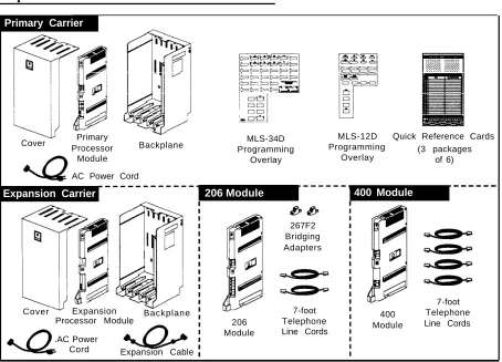
Before installing the system, be sure you read the safety instructions on page 2-ii. In addition, be sure you have the parts shown in Figure 2-3 (if not, call the Helpline). You will have up to four packages of system components; Figure 2-3 shows the contents of each package in the area marked by a dashed line.
Required Parts
Primary Carrier
Cover Primary
Processor Backplane
Module
AC Power Cord
Expansion Carrier 206 Module 400 Module
Cover Expansion
Processor Module Backplane
AC Power
Cord Expansion Cable
MLS-34D MLS-12D Quick Reference Cards
Programming Programming (3 packages
Overlay Overlay of 6)
206 Module
267F2 Bridging Adapters
7-foot Telephone Line Cords
400 Module
7-foot Telephone Line Cords
Installing the Carriers and Modules
Backplane
1
A) Hold the backplane against the2
wall. (If you are also installing theexpansion carrier, plan to install it to the right of the primary carrier, leaving 6” to 24” between carriers.) Using the four screw keyholes in the backplane as a template, mark screw locations on the wall. Start four #12 screws, leaving the screw heads approximately 1/4” away from the wall. Slip the backplane onto the screws and tighten them. B) If you are mounting the expansion carrier, repeat this step.
Primary Processor Module
Power Jack Expansion
Processor Module
4
If you have installed both carriers, plug the ends of the expansion cable into the two processor modules and tighten the screws. Route both ends of the cable through the hooks on the fronts of the modules.NOTE: The colored plastic filters on the expansion cable should rest just below the hooks.
5
WARNING:
Backplane
A) Slide the primary processor module into the center slot of the primary carrier. Push slowly but firmly until the module locks into place with two snaps, and is attached to the rear of the backplane and held in place by the locking tab on the bottom of the slot. Do not force the module. If it does not insert easily, remove the module, clear any obstruction, and reinsert. B) If you have an expansion carrier, slide the expansion processor module into its center slot until the module locks into place.
Main Circuit Breaker
3
Slide the first 206 module into the leftmost slot of the primary carrier backplane. (The system will not work if a 206 module is not installed in this slot.) Going from left to right, install 206 modules first, then any 400 (or 200) modules. The 400 modules must always be to the right of all 206 modules, so the extensions will be numbered consecutively.A) Make sure the main circuit
6
Check all green lights on the breakers on both carriers are pulled fronts of the modules. If a single light out. B) Press the AC power cord is out, pull out the circuit breakers, firmly into the power jack on the top reseat the module, then push in the right side of the primary carrier’s circuit breakers (as you did in step backplane until it locks into place. 5C). If multiple lights are out, pull out Plug the other end of the power cord the circuit breakers, reseat the into a three-prong wall outlet not leftmost module of the ones that are controlled by a switch. Repeat for the out, then push in the circuit breakers. expansion carrier, plugging its cord If the lights are are still out, call the into the same wall outlet. C) Push in Helpline.the circuit breaker on the expansion carrier first, and then push in the circuit breaker on the primary carrier.
Connecting Lines and Extensions
555-1343
555-1344
555-1345
555-1346
Network Interface Jacks
1
Test for dial tone at the network interface jacks before connecting outside lines. Connect a standard touch-tone or rotary phone to the first network interface jack. Lift the handset and listen for dial tone. Repeat for each network interface jack. (If there is no dial tone, contact your localtelephone company before continuing.)
2
A) Connect telephone cords to the line jacks on 206 and 400modules, starting with the top line jack on the leftmost 206 module. B) Route each cord through the hook on the front of module, then through the slot between the module and the base of the backplane. Leave at least two feet of slack in the cords so you can easily reconnect cords after replacing system modules (see “Replacing a System Module” on page 2-12).
3
Connect the free end of each line cord to the appropriate network interface jack.4
Test the lines. Plug a system5
phone into extension 10. Press the line buttons for each outside line and listen for dial tone. Repeat for extensions 16, 22, 28, 34, 40, 46, and 52 (if available).A) Connect modular telephone cords to 206 module extension jacks, starting at the top jack on the leftmost module. B) Route each cord through the hook on the front of the module, then through the slot between the module and the base of the
backplane. Leave at least two feet of slack to allow easy replacement of system modules (see “Replacing a System Module” on page 2-12). Connect each cord to the appropriate wall jack.
Assembling System Phones
Desk Mounting (stand required for MLS-34D; optional for other system phones)
1
A) Plug one end of the handset A) Remove the plastic covercord into the jack on the handset and the other end into the small jack on the left side of the base. If installing an MLS-34D, go directly to step 2 (skip 1B). B) Plug one end of the phone cord into the big jack on the bottom of the phone. Push the cord into place along the channel on the bottom of the phone. If you want to raise the angle of the phone, go to step 2 and install the telephone stand. If not, go to step 3.
2
To install the telephone stand (required for the MLS-34D), gently place the phone upside down, with the low end of the phone to your right. Insert the tab on the narrow end of the stand into the right slot on the bottom of the phone. (For an MLS-34D phone, feed the cord through the stand and plug it in.) Then insert the other tab into the left slot, pushing the stand down and slightly inward until the tab locks into place.3
from the phone and place a labeled button sheet on the phone so the holes on the sheet fit over the buttons. Carefully replace the plastic cover. B) Slide the Quick Reference card under the telephone.
NOTE: If you wall mount a display phone, the display may be difficult to read, so desk mounting is
recommended.
Wall Mounting (stand required for all system phones)
1
Reverse the plastic hook that sits in the earpiece part of the handset cradle.CAUTION:
Do not unscrew the bottom of the phone. To do so will expose you to a risk of electrical shock.
NOTE: Wall mounting instructions apply to corded MLS-model phones only. To wall mount an MLC-6 cordless phone, follow the instructions in the booklet provided with the phone.
2
To install the telephone stand, gently place the phone upside down with the low end of the phone to your right. Insert the tab on the narrow end of the stand into the left slot on the bottom of the phone. (For an MLS-34D phone, feed the cord through the stand and plug it in.) Then insert the other tab into the right slot, pushing the stand down and slightly inward until the tab locks into place.3
Insert the phone cord through the center of the stand and plug it into the jack on the base of the phone, then plug the other end into the modular wall jack. Mount the phone on the wall jack using the screw keyholes on the base of the stand. For proper mounting, the wall jack must be an AT&T 630B connecting block. Finally, connect the handset cord as described in “DeskConnecting and Testing Telephones
1
To connect a phone, plug the modular telephone mounting cord into a modular wall jack or directly into a 206 module extension jack. (If you are connecting a standard phone and its mounting cord is loose, use an AT&T D2R mounting cord instead.)To install two phones (or other devices) on a single extension jack, see the figure on page 2-3.
2
Test the telephone for proper operation. To test the power and lights on a system phone, press and hold the [ # ] button for five seconds. Before releasing the [ # ] button, lift the handset. All lights should light, the ringer should sound, and (on the MLS-12D or MLS-34D phones only) a test pattern should appear on the display. (If not, call the Helpline at 1 800 628-2388.) Replace the handset; the phone is now in normal operating mode.Connecting Paging and Music-on-Hold Devices
PAGE Jack
MUSIC ON HOLD Jack
Volume Control
Paging System Audio Source(optional)
(optional)
Paging System: To install an AT&T
paging system, insert the modular plug for the paging system into the jack labeled PAGE on the processor module. Route the cord as for line and extension cords, then connect it to the loudspeaker paging system.
Music-on-Hold Audio Source: A) To B) To adjust volume, first use a connect an audio source, insert an flathead screwdriver to turn the RCA phono plug into the MUSIC ON volume control on the processor HOLD jack on the primary processor module counterclockwise to the module. Route the cord as you did for lowest setting, and then connect AC line and extension cords, and then power. Place a call on hold and listen connect it to the audio source. while adjusting the volume. If you do
not hear music at any setting, check system programming procedure #602 NOTE: Only the steps for connection to the control unit are provided here. (see Chapter 3).
Connecting MLS-CA24 Intercom Autodialers
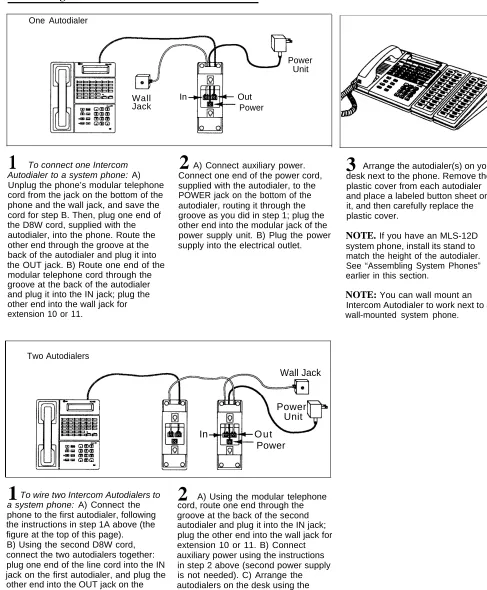
One Autodialer
Power Unit
Wall Jack
In Out
Power
To connect one Intercom Autodialer to a system phone: A) Unplug the phone’s modular telephone cord from the jack on the bottom of the phone and the wall jack, and save the cord for step B. Then, plug one end of the D8W cord, supplied with the autodialer, into the phone. Route the other end through the groove at the back of the autodialer and plug it into the OUT jack. B) Route one end of the modular telephone cord through the groove at the back of the autodialer and plug it into the IN jack; plug the other end into the wall jack for extension 10 or 11.
1
A) Connect auxiliary power.Connect one end of the power cord, supplied with the autodialer, to the POWER jack on the bottom of the autodialer, routing it through the groove as you did in step 1; plug the other end into the modular jack of the power supply unit. B) Plug the power supply into the electrical outlet.
2
3
Arrange the autodialer(s) on yourdesk next to the phone. Remove the plastic cover from each autodialer and place a labeled button sheet on it, and then carefully replace the plastic cover.
NOTE. If you have an MLS-12D system phone, install its stand to match the height of the autodialer. See “Assembling System Phones” earlier in this section.
NOTE: You can wall mount an Intercom Autodialer to work next to a wall-mounted system phone.
Two Autodialers
Wall Jack
Power Unit
In O u t
Power
Replacing a System Module
To replace a system module, first disconnect the AC power cord from the wall outlet, and then slide the control unit cover off the backplane.
Place one hand on top of the module. With the other hand, grip the plastic bracket on the bottom front of the module, and use the middle finger to hold down the locking tab just below the bracket. Slide the module straight out, being careful not to strain the wires connected to the module. (If there is not enough slack in the wires, label and disconnect them before removing the module.)
Programming
3
Contents
Alphabetical List of Programming Procedures
Overview
■ Initial System Setup Copy Settings
■ Changing Settings after Installation Changing the System Clock Adding New Lines
Adding New Extensions
System Programming
■ System Programming OptionsDialing Restrictions and Permissions Setting Up Groups of Extensions Night Service
Setting Up Auxiliary Equipment System Speed Dialing
■ System Programming Procedures The Programming Overlays System Programming Reference
System Speed Dial Programming Reference
Telephone Programming
■ Telephone Programming options Automatic Line Selection Line Ringing
Personal Speed Dialing
Programming Telephone Buttons Programming a Receptionist’s Extension Backup Programming Extension
■ Telephone Programming Procedures Telephone Programming Reference
Alphabetical List of System and Telephone Programming Procedures
For information on a programming procedure, see the page cited in this table. System programming procedures are identified by the procedure code following the procedure name (for example, #305 for Abbreviated Ringing). Telephone programming procedures show only the procedure name (they have no code).
Procedure
Page
Procedure
Page
Abbreviated Ringing #305 3-17 Line Ringing 3-26
Allowed List Assignments #408 3-18 Line Selection, Automatic 3-26
Allowed Phone Number Lists #407 3-18 Lines, Number of #104 3-16
AA/VMS Extensions #607 3-19 Loudspeaker Paging 3-27
Auto Dialing 3-26 Message Light Off 3-27
Automatic Extension Privacy #304 3-17 Message Light On 3-27
Automatic Line Selection 3-26 Music On Hold #602 3-19
Call Forwarding 3-27 Night Service Button #503 3-19
Call Pickup 3-27 Night Service Group Extensions #504 3-19
Calling Group Extensions #502 3-19 Number of Lines #104 3-16
Conference Drop 3-27 Outgoing Call Restriction #401 3-18
Conference, Outside #109 3-16 Outside Conference #109 3-16
Copy Settings #399 3-17 Password, System #403 3-18
Date, System #101 3-16 Personal Speed Dial Numbers 3-26
Day, System #102 3-16 Group Pickup 3-27
Dial Mode #201 3-17 Pickup Group Extensions #501 3-19
Direct Line Pickup 3-27 Privacy 3-27
Disallowed List Assignment #405 3-18 Privacy, Automatic Extension #304 3-17
Disallowed Phone Number Lists #404 3-18 Recall 3-26
Display Language #303 3-17 Recall Timer Duration #107 3-16
Do Not Disturb 3-26 Reset #728 3-16
Doorphone 1 Extension #604 3-19 Restriction, Line Access #302 3-17
Doorphone 2 Extension #605 3-19 Restriction, Outgoing Call #401 3-18
Doorphone Alert Extensions #606 3-19 Ringing, Abbreviated #305 3-17
Drop, Conference 3-27 Ringing, Line 3-26
Emergency Phone Number List #406 3-18 Rotary Dialing Timeout #108 3-16
Extension Hunt Group 3-27 Save Number Redial 3-26
Exclusive Hold 3-26 SMDR Record Type #608 3-19
Fax Machine Extensions #601 3-19 SMDR Top of Page #609 3-19
Group Calling 3-27 Speed Dial Numbers, Personal 3-26
Group Paging 3-27 Speed Dial Numbers, System
Hold Disconnect Time #203
3-20
3-17 System Password #403 3-18
Hotline #603 3-19 System Speed Dial Numbers 3-20
Hunt Group Extensions #505 3-19 Time, System #103 3-16
Language, Display #303 3-17 Toll Call Prefix #402 3-18
Last Number Redial 3-27 Touch-Tone Enable
Line Access Restriction #302
3-27
3-17 Transfer Return Extension #306 3-17
Programming
3
Overview
After you install the system hardware as described in Chapter 2, you can customize the system and individual telephones to meet the requirements of your business. This chapter explains how to use programming to accomplish that.
There are two types of programming:
■ System Programming allows you to customize the system to meet the
needs of your business. When the system is first installed, it uses factory settings that reflect the most common settings, which you can change as needed. The “System Programming Options” section in this chapter explains your choices.
You can program the system from either extension 10 or 11. Because an extension cannot be in program mode and handle calls at the same time, this flexibility allows you to program from extension 11 (the
backup programming extension) while the receptionist at extension 10
(the primary programming extension) continues to handle calls. An MLS-34D telephone is required for programming if your system has any MLS-34D telephones; if not, you can use an MLS-12D.
■ Telephone Programming allows users to customize their telephones
Initial System Setup
After installing the control unit, you set up the system using a combination of system and telephone programming procedures. However, before you program, you need to:
■ Compile a list of system extensions, along with the type of phone at the extension, and identify the lines to assign to each extension.
■ Determine how your company’s receptionist will cover calls so you can choose line ringing options for all employees (for advice see
“Programming a Receptionist’s Phone” later in this chapter).
■ Consider other programming options, such as Line Access Restriction, or Outgoing Call Restriction (for advice see “System Programming Options” later in this chapter).
Once you know how you want the system to work and the information is recorded in the System Planner (available separately), you can program. The programming procedures* you are most likely to use initially include:
■
■
■
System Date (#101), System Day (#102), and System Time (#103) to
set the current date, day and time.
Dial Mode (#201) to identify any rotary lines you may have in your phone
system.
Line Assignment (#301) to assign individual lines to specific extensions.
Line Ringing (Centralized Telephone Programming) to specify when
each available line will start ringing at an extension.
Line Access Restriction (#302) to limit an extension’s access to each
line.
Procedures to identify extensions with fax machines (#601), doorphones ■
■
■
(#604–#606), or automated attendants (#607).
Other programming procedures are optional, but strongly recommended to make the most of your investment. (See “System Programming Options” and “Telephone Programming Options” later in this chapter for details.)
Copy Settings
The recommended way to set up your system is to program one extension for each type of phone in the system, and then use Copy Settings (#399) to
program other phones of the same type, thereby saving the time it would take to program them individually. For example, you can program one MLS-12D phone and then copy its settings to any other extensions that have MLS-12D phones. (See page 3-17 for a list of the programmed settings that are copied.)
* System Programming procedures are identified by a code (# and three digits); Telephone Programming
Changing Settings after Installation
As your business grows or changes, you will probably need to change the way your system was originally programmed. Here are some examples:
Changing the System Clock
You may need to change or reset the system clock for daylight saving time, after a prolonged power failure, or after a complete system reset. To change the system clock, use the following procedures:
System Date (#101) to set the month, day, and year. ■
■ System Day (#102) to set the day of the week.
■ System Time (#103) to set the hour.
Adding New Lines
If you add an outside line to your system after installation, use one or more of the following procedures:
■
■
Dial Mode (#201) to identify the new line as rotary or touch-tone.
Line Assignment (#301) to assign the line to specific extensions.
Line Ringing (Centralized Telephone Programming) to specify when
the line will start ringing at each extension that has the line.
Line Access Restriction (#302) to limit an extension’s access to it. ■
■
NOTE:
Do not use the Number of Lines (#104) programming procedure if you add new lines to the system because the procedure changes Line Access Restriction (#302), Automatic Line Selection, Line Ringing, and Hold Disconnect Time (#203) for existing lines back to factory settings.
Adding New Extensions
If you add an extension to your system after installation, use one or more of the following procedures. Note that you can use Copy Settings (#399) to copy the settings of an existing extension to the new extension.
■
■
■
■
Line Assignment (#301) to assign specific lines to the extension.
Line Access Restriction (#302) to restrict the extension’s access to a
line for placing or receiving calls.
Display Language (#303) to specify the language (English, French, or
Spanish) to appear on a system display phone.
Automatic Extension Privacy (#304) to prevent other extensions with
the same line from joining a call at the extension. This feature is also useful for extensions connected to a modem, fax, or credit card scanner—any device whose function can be disrupted by someone trying to join it. (To program Privacy onto a button of a system phone, so Privacy can be manually turned on and off, see “Telephone
■ Outgoing Call Restriction (#401) to prevent the extension from making certain types of outgoing calls (on all system lines).
■ Disallowed List Assignment (#405) to assign one or more Disallowed Phone Number Lists to the extension. Use the Disallowed Phone Number Lists (#404) procedure to compile the lists of outside numbers that extensions cannot dial.
■ Allowed List Assignment (#408) to assign an Allowed Phone Number List to the extension. Use the Allowed Phone Number Lists (#407) procedure to compile a list of outside numbers that extensions can dial. ■ Group Assignment to place the new extension in Pickup Groups
(#501), Calling Groups (#502), the Night Service Group (#504), or Hunt Groups (#505).
■ Auxiliary Equipment Extensions to identify the new extension as a fax machine (#601), a doorphone (#604-# 606), or an automated attendant (#607).
■ Automatic Line Selection (Centralized Telephone Programming) to specify the order in which the system tries to select an available line (intercom or outside) for an outgoing call, when the user lifts the handset or presses [Spkr] to make a call without first selecting a specific line button.
■ Line Ringing (Centralized Telephone Programming) to specify when each outside line on the extension should start ringing.
System Programming
System Programming Options
This section explains how you can set up your system to operate most efficiently, taking into account your company’s telephone service, personnel, and equipment, as well as the special needs of particular departments.
Dialing Restrictions and Permissions
The system has several procedures for restricting telephone use, and several for overriding those restrictions. You can use any combination of these procedures to design a system that meets your needs. Refer to Table 3-1 at the end of this section for a summary of available dialing restrictions and permissions.
NOTE:
Restricting Access to Outside Lines
A user can access a line either by pressing a button on the phone or by dialing a feature code (Direct Line Pickup). If you do not want a user to access a specific line, use Line Access Restriction (#302) to control an extension’s access to a certain line. For example, you may want a secretary to answer calls on a manager’s line, but not to make any outgoing calls on the line; in this case you can assign the manager’s line to the secretary’s extension and restrict it to “incoming only.” In addition, you may want to make sure no one else can join the manager’s line using Direct Line Pickup. To do this, assign “no access” to that line for all other extensions in the system. The following settings for Line Access Restriction are available:
■ No restriction.
Outgoing only. The extension cannot receive calls on the line (except
■
transferred calls), but can make outgoing calls.
■ Incoming only. The extension can receive but not make calls on the line.
If you restrict a line on an extension to incoming calls only, the user cannot select that line to dial out.
■ No access. The extension can see the status of the line (by looking at the
lights), join a call, and pick up a transferred or held call. However, the extension cannot make or receive calls on the line.
NOTE:
The Line Access Restriction (#302) procedure controls an extension’s access to an outside line. Once an extension is on an outside line, what it can dial is controlled by Outgoing Call Restriction and Disallowed Phone Number Lists, an explained in the next section.
Controlling Calls on Outside Lines
When an extension is allowed access to an outside line, you can use the following procedures to control calling:
Outgoing Call Restriction (#401) controls calling for all lines available on ■
an extension. You have the following choices:
■ No restriction allows long distance, local, and inside calling.
■ Local only allows local and inside calling only (make sure the Toll Call
Prefix is set properly, using procedure #402).
■ Inside only allows intercom calls only.
Disallowed Phone Number Lists (#404) creates lists of numbers that ■
cannot be dialed. The numbers on a Disallowed List can be entire telephone numbers, or numbers of a certain type (such as all numbers in a particular area code). You can store as many as four different lists of up to 10 numbers each.
After you create the Disallowed Phone Number List(s), use the
Disallowed List Assignment (#405) procedure to assign one or more of the lists to a specific extension. When a Disallowed Phone Number List is assigned to an extension, the list applies to all the lines the
■ Night Service causes after-hours calls to ring immediately at the
extensions in the Night Service Group, regardless of Line Ringing during normal day operation. If you define a System Password, turning Night Service on also restricts outside calling by all extensions in the Night Service Group. See page 3-10 for details on Night Service.
Overriding Dialing Restrictions
The following programming procedures provide ways to override all dialing restrictions, except those imposed by Line Access Restriction (#302):
■
■
■
Emergency Phone Number List (#406) defines a list of up to ten
numbers that can be dialed from any extension in the system (if the extension has access to an outside line). A typical number is 911.
Marked System Speed Dial Numbers can be dialed from any
extension with access to an outside line. System Speed Dial numbers are outside telephone numbers that a user can dial automatically by pressing [ Feature ] (or [ # ] a standard phone), followed by a two-digit
code. “Marking” a System Speed Dial number lets any user in the system dial it, overriding any dialing restrictions for the extension.
System Password (#403) creates a password that, when entered at
any MLS-model phone, overrides dialing restrictions for the duration of a call. This means that a person who knows the password can make a call from a restricted extension, as long as the extension has access to an outside line. If you define a System Password, turning on Night Service also restricts outside calling for the Night Service Group. See page 3-10 for details on Night Service.
You can use the following procedure to override all dialing restrictions, except Line Access Restriction and Night Service with a System Password:
■ Allowed Phone Number Lists (#407) allows you to create lists of
numbers that specific extensions are allowed to dial. Even if an extension’s settings for Outgoing Call Restriction and Disallowed Phone numbers would normally prevent the extension from dialing a number, defining the number as an Allowed Phone number lets the extension dial it. (For example, if you put 900 numbers on a Disallowed List but want users to be able to call a specific 900 technical support hotline, put that number in an Allowed List.)
The system stores as many as four different Allowed Lists of up to 10 numbers each. After creating Allowed Lists, use the Allowed List Assignment (#408) procedure to assign one or more of the lists to a specific extension.
Users can always place and receive intercom calls and can always receive transferred calls (even on outside lines not assigned to an extension), regardless of the dialing restrictions placed on their extensions.
NOTE:
Type of Setting for Setting for Setting for Restrictions or Setting for Line Line Access Outgong Call Disallowed Phone Permissions for Assignment Restriction Restriction Number List
the Extension (#301) (#302) (#401) (#404)
Settings that restrict an extension’s access to a specific line
Settings that restrict an extension’s dialing once it gets an outside line
Summary
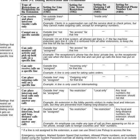
Table 3-1 summarizes the available dialing restrictions and permissions, showing how they can be combined in a variety of ways to customize an extension’s dialing privileges.
Table 3-1. Dialing Restrictions and Permissions
Can receive No outside lines* — “Inside only” —
and place “assigned” intercom
(inside) calls Example: Clerks in a supermarket can call the service desk to check prices, but only they cannot make outgoing calls, except for emergency numbers.
Cannot use a specific outside line
Outside line “not “No access” for — —
assigned” that line
Example: On an 8-line system, all phones get lines 1–7; the fax machine extension gets line 8. Line 8 is removed from all other extensions, to keep the line free for the fax machine.
Can only Outside line “No access” for — —
monitor call “assigned” that line activity and
pick up held Example: The receptionist’s phone has the boss’ private line, so the receptionist calls on a hold.can see when the boss is on the line and can pick up calls the boss has put on specific line
Can only Outside line “Incoming only” —
receive calls on “assigned” for that line a specific line
Example: A line is only used for taking sales orders.
—
Can place Outside line* may “Outgoing only” — —
outgoing calls be “assigned” for t