Transactions of the 17th International Conference on Structural Mechanics in Reactor Technology (SMiRT 17) Prague, Czech Republic, August 17 –22, 2003
Paper # C02-1
A Sensitivity Study on the Fuel Rod Hydraulic Instability for the Advanced 16X16
Fuel Development
Sang Youn JEON1), Kyeong Lak JEON1), and Jae Won KIM1)
1) KEPCO Nuclear Fuel Co., Fuel Technology Center, Daejeon, South Korea
ABSTRACT
The fuel rod instability can be occurred because of the axial and cross flow due to the flow anomaly and/or flow redistribution in the lower core plate region of the pressurized water reactor. The fuel rod vibration due to the hydraulic instability is one of the root causes of fuel failure. The verification on the fuel rod vibration and instability is needed for the new fuel assembly design to verify the fuel rod instability. In this study, the fuel rod vibration and stability analyses were performed to investigate the sensitivity of span adjustment of advanced 16X16 fuel assembly design.
KEY WORDS: Advanced 16X16 fuel assembly design, fuel rod vibration, fuel rod instability, axial flow, cross flow, span adjustment, pressurized water reactor, fuel failure
INTRODUCTION
The fuel rod instability can be occurred because of the axial and cross flow due to the flow anomaly and/or flow redistribution in the lower core plate region of the pressurized water reactor. The flow anomaly causes a vortex to periodically form in the lower plenum area and results in a slight pressure depression in the core area above the vortex. A resulting crossflow is caused by coolant flowing into the low pressure core region caused by this vortex. Besides the lower plenum flow anomaly crossflow, a typical fuel assembly will also experience crossflow due to the flow redistribution from the coolant passing through the lower core plate holes. The fuel rod vibration due to the hydraulic instability is known as one of the root causes of fuel failure. The verification on the fuel rod vibration and instability is needed for the new fuel assembly design to avoid the fuel rod instability.
FUEL ROD MODEL AND MODAL ANALYSIS
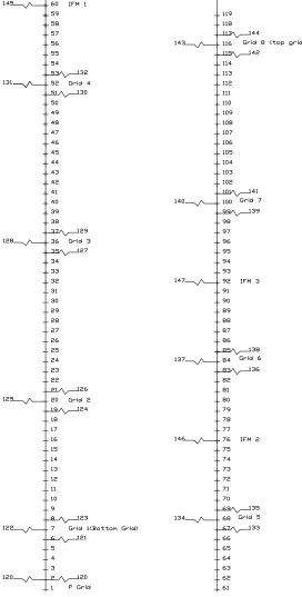
The analysis models are based on the advanced 16X16 fuel assembly design with 6 ZIRLOTM Mid Grids, Inconel Top
and Bottom Grids, 3 ZIRLOTM IFM Grids, Protective Grid, and Long Solid End Plug. The finite element model for the
16NGF fuel rod design is shown in Figure 1. As shown in the Figure 1, the fuel rod models consist of the two-dimensional beam and one-dimensional linear spring elements. The fuel rod is supported by two dimples and one spring. The grid spring force relaxation is modeled by reducing the tangential spring stiffness. To simulate the EOL (End-Of-Life) condition, a reduced tangential stiffness of 10% of BOL (Beginning-Of-Life) value is assumed for the fuel rod at all grid dimple elevations. The model considers the geometric configuration, mass density distribution, and material properties corresponding to the operating temperature. The input parameters are based on nominal design dimensions. The individual density for the finite element model is corrected to include the added mass effects for the submerged fuel rod. The displaced fuel rod volume and coolant density is used to calculate the added mass correction factor. The radial and tangential stiffness of spring and dimple represents the fuel rod supports. The radial stiffness is adjusted to the temperature
of 600oF. The span adjustments are achieved by moving down the first mid grid and by moving up the bottom inconel grid.
The fuel rod vibration analysis was performed using the WECAN computer code [1]. The reduced modal analysis is used to determine the natural frequencies and mode shapes for a linear and undamped structure. This analysis requires the master degrees of freedom of the model. For the fuel rod model, the master degrees of freedom were specified at all nodes on the fuel rod. Table 1 shows the analysis matrix of span adjustments.
FUEL ROD STABILITY ANALYSIS
RESULTS AND EVALUATION
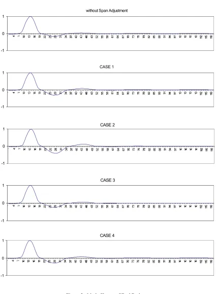
The natural frequencies for the span adjustments are tabulated in Table 2 and the mode shapes for the span adjustments are shown in Figure 3. The change in natural frequencies for each case of span adjustment depends on the amount of span adjustments. There are no significant differences in the natural frequencies for each case of span adjustment. The natural frequencies of the first mode for the span adjustment are about 3 to 4 Hz higher than that of the without span adjustment case. The higher natural frequencies are due to the reduced span length of bottom span. The natural frequencies of the other modes
for the span adjustment case are almost same as the without span adjustment case.The mode shapes of span adjustment cases
have better performance from a fuel rod stability and fretting wear standpoint. Based on the results, the dynamic characteristics of the fuel rod for the each case of span adjustment are very similar.
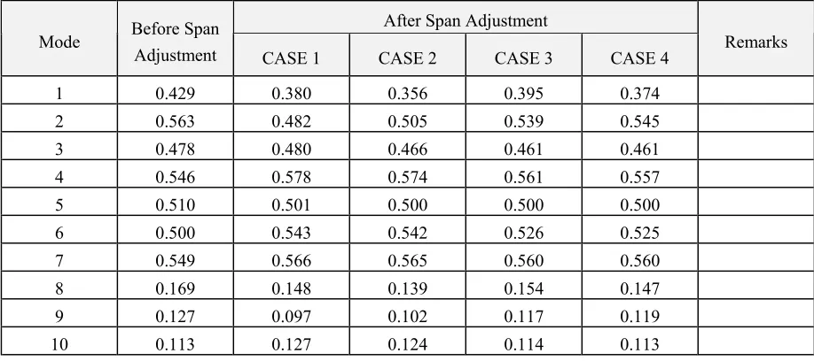
The instability ratio (U-Effective/U-Critical) and vibration amplitude are tabulated in Table 3. The instability ratio and vibration amplitude of the span adjustment cases are lower than that of the without span adjustment case. Based on the results, the fuel rod with span adjustment has better performance from a fuel rod stability and fretting wear standpoint. The improvement mainly depends on the amount of span adjustment of the first mid grid and bottom grid. There are some restrictions for the moving up and down of spacer grid. The moving up of the bottom grid is restricted by the grid-to-grid overlap requirement and the moving down of the first mid grid is restricted by the grid-to-grid overlap requirement and the clearance requirement between first mid grid sleeve and guide thimble flow hole [3]. The first mid grid can be moved down by 0.5 in. and the bottom grid can be moved up by 1.0 in. due to the restrictions. Based on the results and restrictions, a new grid axial elevation for the advanced 16X16 fuel assembly development was proposed by evaluating the vibration characteristic and instability ratio for each span adjustment case. The proposed span adjustment considering these restrictions is moving down the first mid grid by 0.5 in. and moving up the bottom grid by 1.0 in.
CONCLUSIONS
The fuel rod vibration and stability analyses were performed to investigate the sensitivity of span adjustment of advanced 16X16 fuel assembly design. The natural frequencies of the first mode for the span adjustment are about 3 to 4 Hz higher than that of the without span adjustment case. The mode shapes of span adjustments are almost the same. The fuel rod with span adjustment has better performance from a fuel rod stability and fretting wear standpoint. The improvement depends on the amount of span adjustment of the first mid grid and bottom inconel grid. The proposed span adjustment considering some restrictions is moving down the first mid grid by 0.5 in. and moving up the bottom inconel grid by 1.0 in.
REFERENCES
Table 1. Span Length between 1st Grid and 2nd Grid
Items 1
st Grid Move-Up
(in.)
2nd Grid Move-Down
(in.)
Span Length (in.) Standard 16X16
(Before Span Adjustment) - - 24.43
CASE 1 0.50 0.70 23.23
CASE 2 1.00 0.70 22.73
CASE 3 0.50 0.35 23.58
Advanced 16X16 (After Span Adjustment)
CASE 4 1.00 0.35 23.08
Table 2. Natural Frequencies of Fuel Rod
After Span Adjustment
Mode Before Span
Adjustment CASE 1 CASE 2 CASE 3 CASE 4 Remarks
1 34.105 37.273 38.645 36.375 37.775
2 43.411 43.172 43.252 43.335 43.359
3 45.014 44.392 44.484 44.752 44.801
4 47.339 46.569 46.614 46.938 46.978
5 49.942 49.319 49.336 49.575 49.597
6 52.255 51.947 51.952 52.062 52.070
7 53.656 53.606 53.607 53.624 53.625
Table 3. Instability Ratio and Vibration Amplitude
Instability Ratio
After Span Adjustment
Mode Before Span
Adjustment CASE 1 CASE 2 CASE 3 CASE 4 Remarks
1 0.429 0.380 0.356 0.395 0.374
2 0.563 0.482 0.505 0.539 0.545
3 0.478 0.480 0.466 0.461 0.461
4 0.546 0.578 0.574 0.561 0.557
5 0.510 0.501 0.500 0.500 0.500
6 0.500 0.543 0.542 0.526 0.525
7 0.549 0.566 0.565 0.560 0.560
8 0.169 0.148 0.139 0.154 0.147
9 0.127 0.097 0.102 0.117 0.119
10 0.113 0.127 0.124 0.114 0.113
Vibration Amplitude
After Span Adjustment
Mode Before Span
Adjustment CASE 1 CASE 2 CASE 3 CASE 4 Remarks
1 1.020 0.774 0.684 0.847 0.759
2 0.311 0.290 0.293 0.306 0.307
3 0.289 0.289 0.284 0.280 0.280
4 0.259 0.284 0.281 0.268 0.268
5 0.222 0.241 0.241 0.234 0.233
6 0.207 0.217 0.217 0.212 0.211
7 0.182 0.192 0.192 0.188 0.188
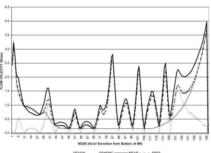
Cross Flow Velocity Distribution
•• •• ••
Axial Flow Velocity Distribution
0.0 0.5 1.0 1.5 2.0 2.5 3.0 3.5 4.0 4.5
1 6 11 16 21 26 31 36 41 46 51 56 61 66 71 76 81 86 91 96
101 106 111 116 121 126 131 136 141 146 151 156
NODE (Axial Elevation from Bottom of BN)
F L O W V E L E C IT Y (ft/ se c)
DESIGN GENERIC LINEAR SRSS
CASE 1
-1 0 1
CASE 2
-1 0 1
CASE 3
-1 0 1
CASE 4
0 1
without Span Adjustment