ABSTRACT
WEN, YUE. Automatic Customization of Powered Knee Prostheses for Individual User using Adaptive Dynamic Programming. (Under the direction of Dr. He Huang.)
Advanced powered prostheses have demonstrated the potential to restore natural gait
and decrease the energy expenditure of amputees during different locomotion modes.
However, those benefits are dependent on the control parameters of the powered
prosthe-ses which are manually and experimentally fine-tuned for each individual user for each
locomotion mode. It is very impractical to adjust a large number of parameters
simultane-ously in clinics for each amputee patient. In addition, this manual configuration procedure
increases the financial cost of advanced prostheses, and the time cost for both clinicians
and amputee patients. This tuning procedure greatly hindered the wide use of the advanced
prostheses. In this thesis, we propose a new method using machine learning to
automati-cally configure the control parameters of powered knee prostheses to fit the behavior of
individual amputee users.
As, safety is the rule of thumb when involve human participants. To validate our novel
approach, we built an OpenSim model to simulate a human-prosthesis system, of which
one knee joint was regulated by a commonly used finite state machine impedance controller.
We implemented and compared two online, model-free adaptive dynamic programming
(ADP) controllers, direct heuristic dynamic programming (dHDP) and the neural fitted
Q with continuous action (NFQCA), to automatically tune the 12 impedance parameters
of the prosthetic knee joint. Both ADP controllers learned to tune the high dimension
impedance parameters and achieved balanced walking, but dHDP outperformed NFQCA
in this application during a 200 gait cycle-based testing.
for the human-prosthesis system, which constantly subjects to measurement noise,
envi-ronment change, and human body caused variations. We modified the dHDP algorithm
to automatically tune the 12 impedance parameters of an experimental knee prosthesis
while subject walking with it on the treadmill. To achieve normative knee kinematics, the
ADP observed the knee kinematics, tuned the impedance parameters, and learned the
knowledge/policy through interaction with the human-prosthesis system using
reinforce-ment learning. We tested the ADP-tuner on two subjects (i.e. one amputee subject and one
able-bodied subject) with multiple testing sessions. The ADP-tuner learned to reach target
gait kinematics in an average of 300 gait cycles or 10 minutes of walking.
Besides restoration of normal knee kinematics, can we improve amputee’s gait
sym-metry and efficiency by personalizing the prosthesis control and/or guided gait training?
Understanding the human-prosthesis physical interaction is vital to build the intelligent
prosthesis that truly benefits the amputee users. With the ADP-tuner, we modulated the
control of robotic knee prosthesis to investigated the relationship between the prosthetic
knee kinematics and human-prosthesis gait performance. Across 6 subjects (3 amputee
subjects and 3 able-bodied subjects), we found that the prosthetic impulses are related
with the prosthetic knee kinematics and that the inter-limb impulse is significantly and
consistently correlated with stance time symmetry. This provides the knowledge to
poten-tially improve gait symmetry and efficiency with both prosthesis control and guided gait
training for amputee by monitoring anterior-posterior impulse components.
Our long-term goal is to restore/enhance amputee’s daily life with advanced robotic
prosthesis. With this in mind, we will focus on 1) realizing adaptive robotic knee prostheses
that can adapt to users while they walking with it in the real world (i.e. with changing tasks),
2) identifying the optimization goals for human-prosthesis system that matter to amputee,
© Copyright 2019 by Yue Wen
Automatic Customization of Powered Knee Prostheses for Individual User using Adaptive Dynamic Programming
by Yue Wen
A dissertation submitted to the Graduate Faculty of North Carolina State University
in partial fulfillment of the requirements for the Degree of
Doctor of Philosophy
Biomedical Engineering
Raleigh, North Carolina
2019
APPROVED BY:
H. Troy Nagle Jason Franz
Jennie Si External Member
Min Chi
He Huang
DEDICATION
To my parents,
BIOGRAPHY
Yue Wen was born in a small village in Handan, Hebei in Febrary 1986 and graduated from
high school in 2007. Yue received the Bachelor of Science in Automation from Wuhan
University of Technology, Wuhan, China, in 2011, and the Master of Science in Control
Engineering and Control Theory from Huazhong Univerisity of Science and Technology,
Wuhan, China, in 2014. In the two year graduate study, he focused on the research on hand
rehabilitation of people with stroke through functional electrical stimulation and exo-hand.
Through this opportunity, he gained strong interests in the biomedical engineering and
rehabilitation.
After finishing his M.S. degree, Yue started to pursue his Ph.D. degree in the
Neuromus-cular Rehabilitation Engineering Laboratory (NREL) under Dr. Helen Huang’s supervision
at the NCSU/UNC Joint Department of Biomedical Engineering at North Carolina State
University and the University of North Carolina at Chapel Hill. Within 5 years at NREL, he
focused on improving the personalization procedure of powered lower limb prosthesis
through reinforcement learning approach, funded by National Science Foundation. His
research interests include adaptive control of robotic prostheses and assistive robotic
de-vices, machine learning, human motion analysis, and gait analysis. As February of 2019, he
has co-authored 4 journal articles and 5 peer-reviewed conference papers. In addition, Yue
ACKNOWLEDGEMENTS
This dissertation work would never be possible without those people who are willing to
support and help me during my graduate study.
I would like express my deepest appreciation to my advisor, Dr. Helen Huang, for her
endless support for the past five years, for her rigorous guidance, enthusiastic
encourage-ment, and constructive critiques on my research projects and manuscript preparation,
and to Dr. Jennie Si for her time and efforts in advising me in machine learning. And many
thanks to my committee members, Dr. Chi Min, Dr. Jason Franz, Dr. Troy Nagle, for their
valuable time, and concrete suggestions on my research topics.
I would like to thank my research mates. Ming Liu, for his supports on mechanical
de-sign and control development, and insightful discussions about research and life; Stephanie
Huang, for her constructive suggestions on experimental design and data analysis; Andrea
Brandt, for those valuable discussions on research questions and bio-mechanical
analy-sis, for her help with participant recruitment, experiments, manuscript editing; to all lab
members at NREL for valuable experience in group meeting, journal club, and consulting
support.
Special thanks to Derek Frankena, CPO and Martha Soyars, PT, for their tremendous
help with subject training and experimental setup, to all participants for their valuable time
and contribution to my research.
Last but not least, I would like to thank my cohort: Lizhi Pan, Minhan Li, for their
accompany and support for late night study, adventures in the holidays. I would also thank
my friends (Mengying Wang, Zhongcan Xiao, etc.) for their encouragement, help, and
TABLE OF CONTENTS
LIST OF TABLES . . . vii
LIST OF FIGURES. . . viii
Chapter 1 Introduction. . . 1
1.1 Background . . . 1
1.1.1 Powered lower limb prostheses . . . 1
1.1.2 Customization of powered knee prostheses . . . 4
1.2 Optimization of powered knee prostheses . . . 5
1.2.1 Human-in-the-loop optimization . . . 5
1.2.2 Optimization goal of powered knee prostheses . . . 7
1.3 Significance . . . 9
1.4 Objective and Outline . . . 11
References . . . 13
Chapter 2 A New Powered Lower Limb Prosthesis Control Framework Based on Adaptive Dynamic Programming . . . 19
2.1 Abstract . . . 19
2.2 Introduction . . . 20
2.3 The human-prostheses control platform . . . 23
2.4 ADP based Impedance Control . . . 26
2.5 Implementation . . . 30
2.6 Results and comparisons . . . 36
2.7 Discussions and Conclusions . . . 37
References . . . 40
Chapter 3 Online Reinforcement Learning Control for the Personalization of a Robotic Knee Prosthesis . . . 44
3.1 Abstract . . . 44
3.2 Introduction . . . 45
3.3 Prosthetic knee control problem formulation . . . 49
3.3.1 Human-prosthesis configuration . . . 50
3.3.2 Prosthetic knee finite-state machine impedance controller . . . 50
3.3.3 Representation of knee kinematics . . . 51
3.3.4 Human-prosthesis system tuning process . . . 51
3.4 The ADP-tuner . . . 53
3.4.1 Utility function/reinforcement signal . . . 53
3.4.2 Critic neural network . . . 54
3.5 Design considerations of online learning for human subjects . . . 57
3.5.1 Safety bounds . . . 58
3.5.2 Robust feature extraction . . . 59
3.5.3 Human variability . . . 59
3.5.4 Prevention of faulty reinforcement signal . . . 60
3.5.5 Termination criteria . . . 60
3.6 Experimental design . . . 61
3.6.1 Participants . . . 61
3.6.2 Prosthesis fitting and subject training . . . 61
3.6.3 Experiment protocol . . . 62
3.6.4 Data analysis . . . 64
3.7 Results . . . 64
3.8 Discussion . . . 71
3.8.1 Feasibility and reliability . . . 71
3.8.2 Efficiency . . . 73
3.8.3 Learning outcome . . . 74
3.8.4 Implications of the results . . . 75
3.8.5 Limitations and future work . . . 76
3.9 Conclusion . . . 77
References . . . 78
Chapter 4 Influence of the Prosthesis Control on the Gait Symmetry . . . 84
4.1 Introduction . . . 84
4.2 Method . . . 87
4.2.1 Human-prosthesis system . . . 87
4.2.2 Reinforcement learning based auto-tuner . . . 89
4.3 Experiments . . . 92
4.3.1 Experimental protocol . . . 92
4.3.2 Data processing and analysis . . . 95
4.3.3 Statistical analysis . . . 98
4.4 Results . . . 99
4.4.1 Range of exploration . . . 99
4.4.2 Relationship between prosthetic knee kinematics and AP impulses . 99 4.4.3 Effects of impulse variables to human gait symmetry . . . 102
4.5 Discussion . . . 103
4.6 Conclusion . . . 107
References . . . 109
Chapter 5 General Conclusion and Future Work . . . 114
5.1 General Conclusion . . . 114
LIST OF TABLES
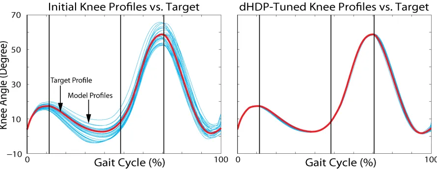
Table 2.1 Upper bound and lower bound of peak error and duration error . . . . 27 Table 2.2 Effects of ADP controller specifications on control performance . . . . 35 Table 2.3 Test results of dHDP after training . . . 37 Table 2.4 Test results of NFQCA after training . . . 37
Table 3.1 Post-tuning impedance parameters of three testing sessions for two subjects . . . 70
Table 4.1 Subject information . . . 93 Table 4.2 Prosthetic braking impulse estimation using angle features of
pros-thetic knee kinematics . . . 102 Table 4.3 Prosthetic propulsive impulse estimation using angle features of
pros-thetic knee kinematics . . . 103 Table 4.4 Correlation analysis between impulse measurements and stance time
symmetry index . . . 103 Table 4.5 Correlation analysis between impulse measurements and step length
LIST OF FIGURES
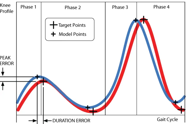
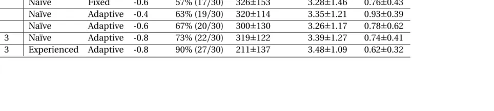
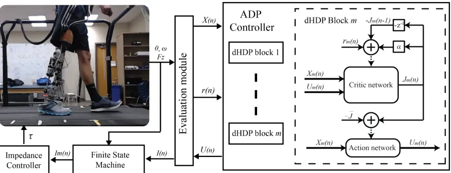
Figure 2.1 Human-prosthesis FS-IC control platform facilitated by OpenSim. One ADP controller is designed for each phase (m =1, 2, 3, 4) of the FSM to provide respective impedance parameter values[refer to (2.1)] for the OpenSim during each gait cyclen. . . 21 Figure 2.2 Red line: target knee profile. Blue line: simulated knee trajectory.
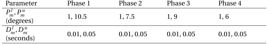
Vertical lines: transitions between gait phases, as determined by the FS-IC transition rules. . . 24 Figure 2.3 Left: initial knee angle profiles. Right: dHDP-tuned knee angle profiles
(light blue) in run 2 of scenario 3. . . 34
Figure 3.1 Block diagram of ADP-tuner, an automatic robotic knee control pa-rameter tuning scheme by dHDP with amputee in the loop. The learn-ing control system operates at three different time scales: 1) real-time impedance controller provides outputs at 100 Hz to regulate the joint torque; 2) the finite-state machine runs at the gait frequency (denoted by time indexg) with four phases per gait cycle; 3) the dHDP gener-ated control is updgener-atedIm,nevery few gaits (denoted by time indexn) to update the impedance parameters. The respective variables in the figure are defined and discussed in Sections II and III. The ADP-tuner consists of four dHDP blocks (m =1, 2, 3, 4) corresponding to four gait phases in the finite-state machine impedance controller. . . 47 Figure 3.2 Feature representation of near-normal knee kinematics during one
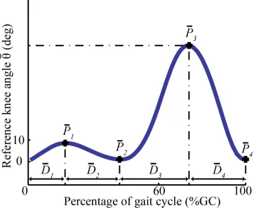
gait cycle was used as learning control target, where ¯Dmindicates the angle feature, and ¯Pm indicates the duration feature. The phase index is indicated bym=1, 2, 3, 4. The start at 0%, and the finish at 100% are the heel strike events, and 60% is approximate toe off time. . . 49 Figure 3.3 Comparison of knee kinematics by RMSE between pre-tuning and
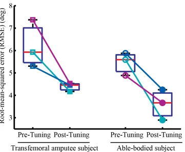
post-tuning across multiple testing sessions. The square markers represent the testing sessions from the TF subject, and circle markers represent the testing sessions from AB subject. Open marker repre-sents the pre-tuning condition, and closed marker reprerepre-sents the post-tuning condition. . . 65 Figure 3.4 Peak error comparison between pre-tuning and post-tuning
Figure 3.5 Duration error comparison between pre-tuning and post-tuning con-ditions of the TF subject (a) and the AB subject (b) for each phase. Each bar represents the mean error of three testing sessions, and the error bars denote one standard deviation from the mean. . . 66 Figure 3.6 Peak error and duration error during the four phases for a
representa-tive tuning procedure. (a) stance flexion phase, (b) stance extension phase, (c) swing flexion phase, and (d) swing extension phase. The red dots were times when the−1 reinforcement signals incurred, and the blue dots were times when the−0.8 reinforcement signals incurred. The horizontal blue areas, which centered at zero, indicate the tolerance ranges for each feature. The paired horizontal red lines indicate the allowed maximum and minimum exploration limits for each feature. . . 67 Figure 3.7 Impedance parameters of the four phases during a representative
tun-ing procedure. (a) stance flexion phase, (b) stance extension phase, (c) swing flexion phase, and (d) swing extension phase. The meanings of the red and blues dots are the same as in Fig. 3.6. . . 68 Figure 3.8 Learned ADP auto-tuner on-line evaluation results. (a) Trends of
angle error along tuning iterations. (b) Trends of duration error along tuning iterations. (c) Changing ˆJ values as learning proceeded. (d) RMSE along tuning iterations. . . 72
Figure 4.1 Feature representation of near-normal knee kinematics during one gait cycle was used as learning control target, where ¯Dmindicates the angle feature, and ¯Pm indicates the duration feature. The phase index is indicated bym=1, 2, 3, 4. The start at 0%, and the finish at 100% are the heel strike events, and 60% is approximate toe off time. . . 88 Figure 4.2 Framework of the human-in-the-loop auto-tuning procedure. (A and
Figure 4.3 The features of the prosthetic knee kinematics covered a wide range during the exploration for each subject. The stance flexion angle and stance extension angle during stance phase varied from 0 to 20 degrees and -8 to 10 degrees respectively. And the swing flexion angle and swing extension angle covered range of 45 to 60 degrees and -8 to 10 degrees respectively. . . 100 Figure 4.4 Stance time SI, step length SI, propulsion SI, and braking SI changed
significantly during the control parameter exploration for all six sub-jects. The mean and standard deviation of the iterations with maxi-mum and minimaxi-mum values are compared. Paired t-test reveal signifi-cant difference for all measurements (p<10−3). a) and b) The stance
time SI and step length SI covered a wide range relative to variances without control change (3% for stance time SI, 5% for step length SI). All subjects cannot generate perfect stance time symmetry, but some of them can generate perfect step length symmetry. c) and d) The impulse symmetry indexes also varied a wide range compared to their variance without control change (17% for propulsion SI, 23% for braking SI). Most of the subjects can generate perfect braking symmetry (SI equals to 0), while only one of the subject can generate perfect propulsion symmetry. . . 101 Figure 4.5 Correlation between inter-limb impulse and stance time symmetry
index. (a)-(c) are from 3 amputee subjects, and (d)-(f ) are from 3 able-bodied subjects. The stance time symmetry index is positive with longer stance time with intact limb, and vice versa. The inter-limb impulse was the net impulse of the transition impulse at transition from intact limb to prosthetic limb (summation of propulsive im-pulse of intact limb and braking imim-pulse of prosthetic limb in one gait cycle). And the impulse was normalized to body weight. More than 150 samples were recorded for each subject. Dots represent the averaged measurement pair from each iteration. Red line is the least squares fits results. . . 105 Figure 4.6 Block diagram of the prosthesis control parameters optimization for
CHAPTER 1:
Introduction
1.1
Background
1.1.1
Powered lower limb prostheses
Advanced powered lower limb prostheses have shown great potential to allow lower limb
am-putee fulfilling different locomotion tasks (e.g. level ground walking, stair ascend/descend,
ramp ascend/descend) more naturally[1–4]and efficiently[5–7]. Compared with passive
prostheses, these advanced powered prostheses share common features: 1) an active
ac-tuator that provides net power at the prosthetic joint, and 2) a controller that emulates
the behavior of biological joints. The prostheses control typically consists of a finite state
machine and a low-level controller to regulate the properties of the prosthetic joints, such
as impedance, within each walking gait phase. The prostheses control are flexible to
ac-commodate different locomotion mode for individual user through modifying the control
parameters, which also means the control parameters need to be customized for each
individual user for each locomotion mode.
In the last decades, many studies has been done to improve the mechanical design of the
powered knee prosthesis. Sup et al. designed a powered ankle-knee prosthesis with
motor-driven ball screw assembly through slider-crank linkage, and applied finite-state-based
impedance controller to restore walking and standing function[8]. Martinez-Villalpando
et al. designed a powered knee prosthesis with two series-elastic actuators in
agonist-antagonist arrangement with finite-state controller to restore level-ground walking[1].
con-trolled by finite-state controller with user intention detection[9]. Rouse et al. applied a
clutchable series-elastic actuator mechanical structure to improve the efficiency of powered
knee prosthesis, which is also controlled by finite-state impedance controller[10]. Lenzi et
al. designed a lightweight robotic knee prosthesis with a hybrid actuation system to provide
stair ambulation capability[11].
In addition, different control methods have been applied to extend the functions and
improve the performance of the powered knee prostheses. Many studies have applied
finite state machine controllers to restore different locomotion tasks and validate the
performance of powered knee prostheses[1, 8–10, 12]. Typically, the finite state machine
controller includes 12 to 15 individual control parameters to mimic the biological function
of the knee joint[4, 8, 12–15]. Lately, many variant forms of finite state controller have
been explored to further improve the performance and/or decrease the number of control
parameters. Hoover et al. applied direct myoelectric (EMG) control for powered knee
prosthesis control on stair ascent task. Transfemoral amputee showed robust and repeatable
performance through combining proportional myoelectric torque and a state-determined
knee impedance[16]. To improve the robustness of the controller, Gregg et al. introduced
virtual constraint control for powered knee prosthesis control, which used effective shape
as a virtual constraint during stance phase and PD control during swing phase[17]. Pfeifer
et al. proposed to define joint stiffness and moment requirements as functions of joint
angle, and incorporated the idea with a finite-state controller to improve the prosthetic
knee moment performance[18]. With intact-leg quasi-stiffness profiles of the knee and
ankle joint at different walking speeds, Lenzi et al. designed the speed-adaptive control of
powered ankle-knee prostheses with walking-speed estimation and finite-state machine
controller[19].
potential to restore natural gait under different locomotion tasks and improve the gait
efficiency for amputees. Many studies have shown that the powered knee prostheses allow
amputee generating gait kinematics that are relatively closer to healthy gait, compared
to walking with passive-elastic prostheses for over ground walking[1, 2], upslope walking
[3], stair ascent and stair descent [4]. Ledoux et al. investigated the metabolic effort of
transfemoral amputees for stair ascent with a powered prosthesis and a passive prosthesis,
and the results demonstrated that the oxygen consumption and stair ascent time decreased
when walking with powered prosthesis[5]. Wolf et al. demonstrated that knee power of
the intact limb significantly less during stair ascent when walking with a powered knee
prosthesis than when walking with a passive knee prosthesis[6]. Willimas et al. studied the
gait performance of transfemoral amputees when walking with different knee prostheses
(i.e. a OttoBock C-Leg and a powered knee prosthesis), and demonstrated that, when
walking with powered knee prosthesis, the hip range of motion symmetry between legs
improved, prosthetic knee power increased, and pelvis-torso twist coupling decreased[7].
To achieve the aforementioned benefits, the prostheses control need to be tuned for
each individual user so as to accommodate human variances in term of weight, physical
ability, etc.[1, 2, 4, 9, 11, 16, 17, 20]. For clinical usage, when the users’ physical condition
changed or their behavior changed after adapting to the device, their gait performance
will be deteriorated due to the unmatched control parameters. Therefore, they need to
re-visit the clinic to re-tune the control parameters to maintain the performance of the
prostheses. Currently, the tuning process, also called customization process, of the powered
1.1.2
Customization of powered knee prostheses
Traditionally, clinicians/experts manually and heuristically tune prosthesis control
param-eters for an individual amputee in the clinic/laboratory by adjusting 1 or 2 parameters
simultaneously while observing the amputee’s gait. The clinician/expert repeats these steps
until the prosthetic knee reaches a desired, subjective performance level. To alleviate the
customization effort for clinicians/experts, many studies has been done to provide insight
about the stiffness of knee joint, decrease the number of control parameters that need to
be tuned.
Some researchers tried to measure the biological knee stiffness so as to guide the
pros-theses control. Pfeifer et al. combined electromyography, kinetic, and kinematic
measure-ments to estimate muscle force and joint stiffness of intact limb at isometric conditions
[21]. Shamaei et al. characterized the quasi-stiffness, which is the slope of the line that fits
moment-angle graph, of the knee joint for the flexion and extension period during stance
[22]. Further, Misgeld et al. developed observer-based knee stiffness estimation approach
that can estimate the stiffness of knee joint in real-time during movement[23]. However,
these approaches can potentially provide good initial guess of the prosthetic knee joint
stiffness, but have not been validated in actual prostheses application.
Alternately, studies have been done to decrease the number of parameters requiring
tuning with different control methods. Simon et al. developed a few strategies to decrease
the number of parameters requiring tuning, including associating the joint impedance
with previous state, joint angle, and prosthesis load[24]. By introducing virtual constraint
control, Gregg et al. decreased the number of control parameters during stance phase from
6 impedance parameters to 4 PD gains[17].
ac-celerate the customization procedure of the powered knee prosthesis, but the remaining
control parameters still needs to be manually tuned. Considering the different locomotion
modes and the high dimension control parameters for each locomotion mode, the manual
tuning/customization procedure is still timing consuming and human-resources expensive,
which greatly hindered the usage of the powered knee prostheses and limited the benefits
of those advanced devices for lower limb amputees. Hence, how to customize this large
number of parameters for an individual user quickly and economically is the critical barrier
for the field of powered prosthesis control. The customization procedure is essentially an
optimization process to find the control parameters that can fulfill certain performance
criteria, such as normative knee kinematics, gait symmetry, etc.Therefore, we propose to optimize the high-dimensional control parameters of the powered knee prostheses au-tomatically through machine learning approach to alleviate/substitute manual tuning procedure.
1.2
Optimization of powered knee prostheses
1.2.1
Human-in-the-loop optimization
Many optimization approaches have been used to customize the control of the wearable
robotics (i.e. prostheses and exoskeleton) with human in the loop. These close-loop
ap-proaches apply different control parameters to the wearable robotic systems, monitor
the physiological measurements in real-time from the robotic-wearer system, and further
change the control parameters based on the physiological measurements. The real-time
measurements can accurately reflect the performance of the user with applied control
parameters. Using different optimization algorithms, the control parameters could be
Currently, human-in-the-loop optimization studies focus on optimizing exoskeleton
control for able-bodied subjects to minimize metabolic energetic cost. Koller et al.
devel-oped gradient descent method to optimize an onset time parameter, as percentage of the
gait cycle, of an ankle exoskeleton to enhance able-bodied persons’ gait efficiency[25].
Zhang et al. developed evolution strategy to optimize four control parameters of an ankle
exoskeleton, which represents the pattern of the ankle joint torque during stance phase, to
minimize the energy cost during walking for able-bodied people[26]. Ding et al. applied
Bayesian optimization to identify two control parameters of hip extension assistance, which
determined the shape of the force profile of the soft hip exosuit, to minimize the metabolic
rate[27]. However, it is hard to migrate these optimization methods to customize the
pow-ered knee prosthesis. One of the reasons is that those methods are difficult to scale up to a
high dimensional (≥5) parameter space. To minimize metabolic cost of able-bodied walk-ing is possible because it is widely accepted that a primary goal for able-bodied persons in
walking is energy minimization[28], and often the relationship between human metabolic
cost and walking condition (e.g. walking speed) follows U-shape functions. Unfortunately,
it is unknown whether this theory is applicable to human-prosthesis system where a human
and robotic limb was connected in series.
For the human-prosthesis optimization, Huang et al. designed a cyber expert system
using fuzzy logic to code the human expert’s (e.g. prosthetist’s) tuning decisions[29], and
applied the cyber expert system to tune the high dimension control parameters of an
ex-perimental knee prosthesis to approach normative knee kinematics. However, this requires
prior/expert knowledge of how to tune the parameters from clinicians/experts, whose
knowledge is subjective and might be biased by their experience.
The optimization of powered knee prostheses subjects to many challenges: 1) it is
prosthesis system has continuous state spaces and relative high dimension control
pa-rameters (≥12), 3) the human-prosthesis system has great uncertainty (e.g. unexpected disturbances) and high measurement noise. The reinforcement learning (RL), also called
adaptive/approximate dynamic programming(ADP), lends itself as an alternative solution
considering its widely application to optimal control problems of nonlinear dynamic
sys-tem[30–32]. Since we need to optimize the high dimension control parameters of powered
knee prostheses without any available human-prosthesis model, action-dependent
heuris-tic dynamic programming (ADHDP) stands out among the series of ADP designs due to its’
model free property (i.e. no need for dynamic model) and promising scalability[31, 33].
Within the branch of ADHDP, neural fitted Q with continuous actions (NFQCA)[34],
direct heuristic dynamic programming (direct HDP or dHDP)[35]have demonstrated the
learning capability in complex and realistic control problems in a on-line manner without
system dynamic model. Furthermore, dHDP and NFQCA (a batch variant of the dHDP[36])
designs have demonstrated their success with many applications of RL control for
con-tinuous state and control problems[36–43].We proposed to introduce the reinforcement learning/adaptive dynamic programming algorithms (dHDP and NFQCA) to automati-cally optimize the high dimension control parameters of the powered knee prostheses while amputee walking with the devices.
1.2.2
Optimization goal of powered knee prostheses
Clinically, people with unilateral lower limb amputation have been reported with
deterio-rated temporal-spatial gait symmetry, loading symmetry, and gait efficiency[44–49]. Lower
limb amputees tend to rely more on the intact side than prosthetic side, resulting longer
intact limb caused reduced prosthetic ground reaction force and impulse[46, 47], and
increased the intact limb loading[48]. This asymmetry gait and overuse of intact limb
could potentially be the causes of many secondary issues, such as back pain, intact knee
osteoarthritis, etc[50]. In addition, people with lower limb amputation present higher
energy expenditure for locomotion than able-bodied people[49].
The ‘super’ powered prostheses would be able to restore the gait symmetry and reduce
the energetic cost to normal level. But, currently, the optimization goals of powered knee
prostheses remain an open question for the field. In clinic/laboratory, experts manually and
iteratively tune the control parameters based on observation of the overall gait performance,
inspection of the prosthetic joint measurements, and the verbal feedback from the subjects.
From control point of view, high level gait performance (e.g. gait symmetry, center of mass
movement, metabolic cost) might be too complex and noisy to directly guide the
high-dimension control parameter tuning procedure, because they usually relies on both the
powered knee prosthesis and the amputee user’s intact joints. And currently, almost all
studies of the powered knee prostheses used normative knee kinematics as an indicator of
good performance.
For human-in-the-loop optimization, the optimization goal should be physiological
measurements that could be influenced by the control parameters. The prosthetic knee
kinematics are the most direct and straightforward measurements of performance of the
human-prosthesis system and determined by the human-prosthesis interaction, i.e. the
behavior of the human user and the control parameters of the prosthesis[8]. In addition,
the knee kinematics are more general across subjects’ physical condition compared to
prosthetic joint torque[51], which is quite different from the biological knee joint due to
the mechanical properties of the powered prostheses are different from intact limb[52].
four distinct features: maximum stance flexion angle, minimum stance extension angle,
maximum swing flexion angle, minimum swing extension angle. Meanwhile, those features
have direct connection with the function of the knee joint:
1. During stance phase, knee flexion at early stance was associated with the energy
absorption, and people increased knee flexion and extensor moments to absorb more
energy when walking speed increases[53]. At late stance, the knee joint re-extended
to generate energy.
2. During swing phase, the knee joint flexes for foot clearance, and then extend to get
ready for next heel strike.
For the first step to optimize the high dimension control parameters of the powered knee prosthesis, we defined the optimization goal as allowing amputee generate nor-mative knee kinematics while walking with the powered knee prosthesis. Further, we would like to investigate the influence of the prosthesis control on the gait symmetry to build up the knowledge for optimization of the gait symmetry.
1.3
Significance
The proposed study is a significant step towards advancing the intelligence of powered
knee prostheses. This study will demonstrate that machine learning methods can learn
complex tuning knowledge through interaction with the human-prosthesis system without
1) prior knowledge of the human tuning procedure, 2) expert/clinician intervention, and 3)
a dynamic model of the powered knee prosthesis. Meanwhile, this study will demonstrate
that the ADP method can tune the high dimensional control parameters of a powered
knee prosthesis for normative kinematics. With those foundations, the ADP method can
Furthermore, the ADP method could potentially lead to intelligent powered knee prostheses
that could adapt to changes in users’ physical environment. Moreover, the ADP method
could potentially be applied to solve the powered ankle prosthesis tuning problem.
The proposed study could change the clinical practice of prosthesis tuning. Currently,
for powered knee prostheses fitting, clinicians need special training from the prosthesis
company to learn how to change the control parameters. In the proposed study, the ADP
tuning algorithm will fill the knowledge gap between the control parameters and the
ob-servable prosthetic knee kinematics, which are more familiar to clinicians. This would
permit clinicians to focus on improving amputee gait performance through modifying the
target knee kinematics without knowledge of the control mechanism and how to change
the control parameters. This could potentially lower both the financial cost and the time
cost of the current fitting procedures for powered knee prostheses.
The proposed framework could serve as a tool to systematically study human walking
objectives. Little is known about the amputees’ objectives during walking and how the
powered prosthesis can better benefit the amputee user besides (or in addition to) enforcing
normative knee kinematics. With the ADP auto tuner proposed here, researchers could
modulate prosthetic knee kinematics systematically to study the relationship between
prosthetic knee joint kinematics and the human gait performance. Ultimately, knowledge of
the relationship between powered knee kinematics and global gait performance could assist
researchers in helping amputees achieve improved gait performance (e.g. gait symmetry,
1.4
Objective and Outline
The design and validation of adaptive dynamic programming algorithm was presented
in Chapter 2 to automatically tune the high-dimension impedance control parameters of
powered knee prosthesis to achieve normative knee kinematics with an OpenSim model. I
modified an OpenSim lower limb model to mimic human walking with a powered knee
prosthesis, and designed and implemented the gait phase-based ADP with reinforcement
learning algorithm for prostheses controller. With the simulation platform, I tested the
feasibility of the ADP auto tuning algorithm for prosthesis tuning and study the effects
of different factors, such as the reinforcement signal, on the performance of the ADP
algorithm.
In Chapter 3, we evaluated the performance of the adaptive dynamic programming
algorithm on tuning the impedance control parameters of powered knee prostheses for
individual users. I recruited one trans-femoral amputee subjects and one able-bodied
subject to validate the ADP algorithm. With each subject, I tested the ADP algorithm with 4
different initial impedance parameter conditions. Afterwards, I validated the improvement
of prosthetic knee kinematics by the root-mean-square error to the normative knee
kine-matics, the knowledge of the ADP algorithm by the observation and decision of the tuning
procedure.
In Chapter 4, I investigated the relationship between the prosthetic knee kinematics
and human-prosthesis gait symmetry through reinforcement learning based auto-tuner.
The knee kinematics were supposed to influenced the human-prosthesis gait symmetry.
However, due to human behavior difference and human-prosthesis setup difference, the
influence of the knee kinematics on the human-prosthesis symmetry might be inconsistent.
prosthetic knee kinematics and gait symmetry. I recruited six subjects (3 unilateral
trans-femoral amputee and 3 able-bodied subjects) to walk with our experimental powered knee
prosthesis on treadmill, during which the reinforcement learning based auto-tuner
ex-plored the control parameters so as to generate varied, but safe prosthetic knee kinematics.
The ground reaction force and knee kinematics were recorded to get gait symmetry index,
impulse, and features of prosthetic knee kinematics. Correlation between knee kinematics
and prosthetic impulses and correlation between the inter-limb impulse measurements
References
[1] E. C. Martinez-Villalpando and H. Herr, “Agonist-antagonist active knee prosthesis: a preliminary study in level-ground walking,”Journal of rehabilitation research and development, vol. 46, pp. 361–373, 5 2009.
[2] F. Sup, H. A. Varol, J. Mitchell, T. J. Withrow, and M. Goldfarb, “Self-contained powered knee and ankle prosthesis: Initial evaluation on a transfemoral amputee,” in2009 IEEE International Conference on Rehabilitation Robotics, ICORR 2009, pp. 638–644, 2009.
[3] F. Sup, H. A. Varol, and M. Goldfarb, “Upslope walking with a powered knee and ankle prosthesis: Initial results with an amputee subject,” IEEE Transactions on Neural Systems and Rehabilitation Engineering, vol. 19, pp. 71–78, 2 2011.
[4] B. E. Lawson, H. A. Varol, A. Huff, E. Erdemir, and M. Goldfarb, “Control of stair ascent and descent with a powered transfemoral prosthesis,”IEEE Transactions on Neural Systems and Rehabilitation Engineering, vol. 21, pp. 466–473, 5 2013.
[5] E. D. Ledoux, S. Member, and M. Goldfarb, “Control and Evaluation of a Powered Transfemoral Prosthesis for Stair Ascent,”IEEE Transactions on Neural Systems and Rehabilitation Engineering, vol. 25, pp. 917–924, 7 2017.
[6] E. J. Wolf, V. Q. Everding, A. L. Linberg, B. L. Schnall, J. M. Czerniecki, and J. M. Gambel, “Assessment of transfemoral amputees using C-Leg and Power Knee for ascending and
descending inclines and steps,”The Journal of Rehabilitation Research and Develop-ment, vol. 49, p. 831, 8 2012.
[7] M. R. Williams, S. D’Andrea, and H. M. Herr, “Impact on gait biomechanics of using an active variable impedance prosthetic knee,”Journal of NeuroEngineering and Rehabilitation, vol. 13, no. 1, pp. 1–11, 2016.
[9] L. Ambrozic, M. Gorsic, J. Geeroms, L. Flynn, R. Molino Lova, R. Kamnik, M. Munih, and N. Vitiello, “CYBERLEGs: A user-oriented robotic transfemoral prosthesis with whole-body awareness control,”IEEE Robotics and Automation Magazine, vol. 21, pp. 82–93, 12 2014.
[10] E. J. Rouse, L. M. Mooney, and H. Herr, “Clutchable series-elastic actuator: Implications for prosthetic knee design,”The International Journal of Robotics Research, vol. 33, pp. 1611–1625, 10 2014.
[11] T. Lenzi, M. Cempini, L. Hargrove, and T. Kuiken, “Design, development, and testing of a lightweight hybrid robotic knee prosthesis,”The International Journal of Robotics Research, p. 027836491878599, 2018.
[12] M. Liu, F. Zhang, P. Datseris, and H. Huang, “Improving Finite State Impedance Con-trol of Active-Transfemoral Prosthesis Using Dempster-Shafer Based State Transition Rules,”Journal of Intelligent & Robotic Systems, vol. 76, pp. 461–474, 12 2014.
[13] E. J. Rouse, L. J. Hargrove, E. J. Perreault, and T. a. Kuiken, “Estimation of human ankle impedance during the stance phase of walking,”IEEE Transactions on Neural Systems and Rehabilitation Engineering, vol. 22, pp. 870–878, 7 2014.
[14] A. Brandt, M. Liu, and H. Huang, “Does the Impedance of Above-knee Powered Pros-theses Need to Adjusted for Load-carrying Conditions ?,” in38th Annual International Conference of the IEEE Engineering in Medicine and Biology Society, (Orlando, FL, USA), 2016.
[15] F. Sup, H. Varol, J. Mitchell, T. Withrow, and M. Goldfarb, “Design and control of an active elctrical knee and ankle prosthesis,”Proceedings of the 2nd Biennial IEEE/ RAS-EMBS International Conference on Biomedical Robotics and Biomechatronics, Scotts-dale, AZ, USA, pp. 523–528, 2008.
[17] R. D. Gregg and J. W. Sensinger, “Towards biomimetic virtual constraint control of a powered prosthetic leg,”IEEE Transactions on Control Systems Technology, vol. 22, no. 1, pp. 246–254, 2014.
[18] S. Pfeifer, A. Pagel, R. Riener, and H. Vallery, “Actuator with angle-dependent elasticity for biomimetic transfemoral prostheses,”IEEE/ASME Transactions on Mechatronics, vol. 20, pp. 1384–1394, 6 2015.
[19] T. Lenzi, L. Hargrove, and J. Sensinger, “Speed-adaptation mechanism: Robotic pros-theses can actively regulate joint torque,”IEEE Robotics and Automation Magazine, vol. 21, no. 4, pp. 94–107, 2014.
[20] L. J. Hargrove, A. J. Young, A. M. Simon, N. P. Fey, R. D. Lipschutz, S. B. Finucane, E. G. Halsne, K. A. Ingraham, and T. A. Kuiken, “Intuitive control of a powered prosthetic leg during ambulation: A randomized clinical trial,”JAMA - Journal of the American Medical Association, vol. 313, no. 22, pp. 2244–2252, 2015.
[21] S. Pfeifer, H. Vallery, M. Hardegger, R. Riener, and E. J. Perreault, “Model-based es-timation of knee stiffness,”IEEE Transactions on Biomedical Engineering, vol. 59, pp. 2604–2612, 9 2012.
[22] K. Shamaei, G. S. Sawicki, and A. M. Dollar, “Estimation of Quasi-Stiffness of the Human Knee in the Stance Phase of Walking,”PLoS ONE, vol. 8, p. e59993, 3 2013.
[23] B. J. Misgeld, M. Lüken, R. Riener, and S. Leonhardt, “Observer-Based Human Knee Stiffness Estimation,”IEEE Transactions on Biomedical Engineering, vol. 64, no. 5, pp. 1033–1044, 2017.
[24] A. M. Simon, K. a. Ingraham, N. P. Fey, S. B. Finucane, R. D. Lipschutz, A. J. Young, and L. J. Hargrove, “Configuring a powered knee and ankle prosthesis for transfemoral amputees within five specific ambulation modes,”PLoS ONE, vol. 9, p. e99387, 6 2014.
[26] J. Zhang, P. Fiers, K. A. Witte, R. W. Jackson, K. L. Poggensee, C. G. Atkeson, and S. H. Collins, “Human-in-the-loop optimization of exoskeleton assistance during walking,”
Science, vol. 356, pp. 1280–1284, 6 2017.
[27] Y. Ding, M. Kim, S. Kuindersma, and C. J. Walsh, “Human-in-the-loop optimization of hip assistance with a soft exosuit during walking,”Science Robotics, vol. 3, p. eaar5438, 2 2018.
[28] R. M. N. Alexander, “Energetics and optimization of human walking and running: The 2000 Raymond Pearl Memorial Lecture,”American Journal of Human Biology, vol. 14, no. 5, pp. 641–648, 2002.
[29] T.-w. P. Huang, K. A. Shorter, P. G. Adamczyk, and A. D. Kuo, “Mechanical and ener-getic consequences of reduced ankle plantar-flexion in human walking,”Journal of Experimental Biology, vol. 218, no. 22, pp. 3541–3550, 2015.
[30] D. P. Bertsekas and J. N. Tsitsiklis,Neuro-Dynamic Programming. Belmont, MA: Athena Scientific, 1996.
[31] J. Si, A. G. Barto, W. B. Powell, and D. Wunsch,Handbook of learning and approximate dynamic programming. New Jersey: John Wiley & Sons, 2004.
[32] W. B. Powell,Approximate dynamic programming: solving the curses of dimensionality. New Jersey: John Wiley & Sons, 2nd ed., 2011.
[33] D. V. Prokhorov and D. C. Wunsch, “Adaptive critic designs,”IEEE Transactions on Neural Networks, vol. 8, pp. 997–1007, 9 1997.
[34] M. Riedmiller, “Neural fitted Q iteration - First experiences with a data efficient neural Reinforcement Learning method,” in16th Eur. Conf. Mach. Learn., (Porto, Portugal), pp. 317–328, Springer, 2005.
[35] J. Si and Y.-t. Wang, “On-Line Learning Control by Association and Reinforcement,”
[36] R. Hafner and M. Riedmiller, “Reinforcement learning in feedback control : Challenges and benchmarks from technical process control,”Machine Learning, vol. 84, pp. 137– 169, 7 2011.
[37] M. Riedmiller, M. Montemerlo, and H. Dahlkamp, “Learning to drive a real car in 20 minutes,” inthe Frontiers in the Convergence of Bioscience and Information Tech-nologies, (Jeju, Korea), pp. 645–650, Springer, 2007.
[38] M. Riedmiller, T. Gabel, R. Hafner, and S. Lange, “Reinforcement learning for robot soccer,”Autonomous Robots, vol. 27, pp. 55–73, 7 2009.
[39] R. Enns and J. Si, “Helicopter Trimming and Tracking Control Using Direct Neural Dynamic Programming,”IEEE transactions on neural networks, vol. 14, pp. 929–939, 7 2003.
[40] R. Enns and J. Si, “Helicopter flight-control reconfiguration for main rotor actuator failures,”Journal of guidance, control, and dynamics, vol. 26, pp. 572–584, 7 2003.
[41] C. Lu, J. Si, and X. Xie, “Direct Heuristic Dynamic Programming for Damping Oscilla-tions in a Large Power System,”IEEE Transactions on Systems, Man, and Cybernetics, Part B: Cybernetics, vol. 38, pp. 1008–1013, 8 2008.
[42] L. Yang, J. Si, K. S. Tsakalis, and A. A. Rodriguez, “Direct heuristic dynamic program-ming for nonlinear tracking control with filtered tracking error,”IEEE Transactions on Systems, Man, and Cybernetics, Part B: Cybernetics, vol. 39, pp. 1617–1622, 12 2009.
[43] W. Guo, F. Liu, J. Si, D. He, R. Harley, and S. Mei, “Online Supplementary ADP Learning Controller Design and Application to Power System Frequency Control With Large-Scale Wind Energy Integration,”IEEE Transactions on Neural Networks and Learning Systems, vol. 27, pp. 1748 – 1761, 3 2016.
[45] E. Isakov, O. Keren, and N. Benjuya, “Trans-tibial amputee gait: Time-distance pa-rameters and EMG activity,”Prosthetics and Orthotics International, vol. 24, no. 3, pp. 216–220, 2000.
[46] P. G. Adamczyk and A. D. Kuo, “Mechanisms of Gait Asymmetry Due to Push-Off Defi-ciency in Unilateral Amputees,”IEEE transactions on neural systems and rehabilitation engineering, vol. 23, pp. 776–785, 9 2015.
[47] M. Schaarschmidt, S. W. Lipfert, C. Meier-Gratz, H. C. Scholle, and A. Seyfarth, “Func-tional gait asymmetry of unilateral transfemoral amputees,”Human Movement Sci-ence, vol. 31, no. 4, pp. 907–917, 2012.
[48] L. Nolan and A. Lees, “The functional demands on the intact limb during walking for ac-tive trans-femoral and trans-tibial amputees,”Prosthetics and Orthotics International, vol. 24, no. 2, pp. 117–125, 2000.
[49] H. L. Jarvis, A. N. Bennett, M. Twiste, R. D. Phillip, J. Etherington, and R. Baker, “Tempo-ral Spatial and Metabolic Measures of Walking in Highly Functional Individuals With Lower Limb Amputations,”Archives of Physical Medicine and Rehabilitation, vol. 98, no. 7, pp. 1389–1399, 2017.
[50] R. Gailey, “Review of secondary physical conditions associated with lower-limb ampu-tation and long-term prosthesis use,”Journal of Rehabilitation Research and Develop-ment, vol. 45, no. 1, pp. 15–30, 2008.
[51] M. P. Kadaba, H. K. H. Ramakrishnan, and M. E. M. Wootten, “Measurement of lower extremity kinematics during level walking,”Journal of Orthopaedic Research, vol. 8, pp. 383–392, 5 1990.
[52] F. Sup, A. Bohara, and M. Goldfarb, “Design and Control of a Powered Transfemoral Prosthesis,”The International Journal of Robotics Research, vol. 27, pp. 263–273, 2 2008.
CHAPTER 2:
A New Powered Lower Limb Prosthesis Control Framework Based on
Adap-tive Dynamic Programming
Yue Wen, Jennie Si, Xiang Gao, Stephanie Huang, Helen Huang
As published in IEEE Transaction on Neural Network and Learning System
2.1
Abstract
This study presents a novel application of adaptive dynamic programming (ADP) for
opti-mal adaptive control of powered lower limb prostheses, a type of wearable robots to assist
the motor function of limb amputees. Current control of these robotic devices typically
relies on finite state impedance control (FS-IC), which lacks adaptability to the user’s
phys-ical condition. As a result, joint impedance settings are often customized manually and
heuristically in clinics, which greatly hinder the wide use of these advanced medical devices.
This simulation study aimed at demonstrating the feasibility of ADP for automatic tuning
of the twelve knee joint impedance parameters during a complete gait cycle to achieve
balanced walking. Given that accurate models of human walking dynamics are difficult
to obtain, the model-free ADP control algorithms were considered. First, direct heuristic
dynamic programming (dHDP) was applied to the control problem and its performance
was evaluated on OpenSim, an often-used dynamic walking simulator. For the comparison
purposes, we selected another established ADP algorithm, the neural fitted Q with
con-tinuous action (NFQCA). In both cases, ADP controllers learned to control the right knee
joint and achieved balanced walking, but dHDP outperformed NFQCA in this application
2.2
Introduction
Adaptive dynamic programming (ADP) is a class of learning- and approximation-based
methods for optimal adaptive control of nonlinear dynamic systems. It combines ideas
from diverse fields including reinforcement learning and machine learning, optimal
con-trol, adaptive concon-trol, and function approximation. In recent years, it has emerged as a
powerful alternative to classic optimal control, especially for complex nonlinear systems,
due to its demonstrated scalability for large systems and flexibility and capability of
learn-ing from data measurements[1, 2]. Additionally, an important class of ADP algorithms
can be implemented without a fully identified system dynamics model. This attribute is
especially useful in applications such as the human-prosthesis control problem studied in
this paper. Human body dynamics vary from person to person; even for a single person,
a full, accurate mathematical description of human walking dynamics is impossible to
acquire. This presents a great challenge and also an exciting opportunity for the ADP or
controls community at large.
Most ADP controls reported in literature were tested on standard benchmark problems
such as single or double inverted pendulums, significantly simplified linear flight models,
and simplified robot arm models. Real demonstrations of ADP controls applied to complex
systems were only available in a handful of cases[3–7]. Furthermore, only a subset of these
cases are capable of model-free learning, namely least square policy iteration (LSPI), neural
fitted Q iteration, neural fitted Q with continuous action (NFQCA), and direct heuristic
dynamic programming (dHDP) and its variants. Among those model-free ADP algorithms,
dHDP and NFQCA stand out because they have been applied to multiple large and complex
dynamic system control problems[3, 4, 6, 8–10]. Thus, they are natural candidates to be
the feasibility of dHDP using simulation studies, it is noteworthy that learning performance
guarantees such as boundedness, stability, and convergence results have recently provided
important theoretical insight on model-free ADP such as dHDP[3, 11–14].
ADP has been used in bipedal robot controls and simulations[15], but our powered
prosthetic leg control (i.e. wearable robot control) is fundamentally different. First, a bipedal
robot is mechanical in nature and its model can be obtained in a mathematical form. Its
control can be completely manipulated by the algorithm designer. On the other hand,
obtaining a model for human-prosthesis control is nearly impossible, and the designer
can only manipulate one or two joints in a prosthesis. All other joints are dominated by
the human wearer. Second, the control law for bipedal robots is not restricted by complex
biomechanics that inherently govern human walking. The human-prosthesis system has
to cope with co-adaptation influenced by human motor control principles.
Figure 2.1Human-prosthesis FS-IC control platform facilitated by OpenSim. One ADP controller is designed for each phase (m=1, 2, 3, 4) of the FSM to provide respective impedance parameter values[refer to (2.1)]for the OpenSim during each gait cyclen.
great promise to augment human movement in able-bodied persons or individuals with
physical disabilities[16], optimal adaptive control of these advanced devices remains a
challenge. Yet, it is much needed[17]. Variations across or within human subjects call for
adaptive control to personalize wearable devices. Since these assistive devices are to enable
or restore motor functions of the users, optimal performance is desired. Given its adaptive
and optimal control nature, ADP algorithms are among the most promising approaches to
this class of challenging problems. As such, this study is the first to address these challenges
and to demonstrate the potential of ADP in personalizing control parameters adaptively
and optimally. The results may transform wearable robot control to better support the
motor function in lower limb amputees.
In powered lower limb prosthetics, finite state impedance control (FS-IC) is the most
utilized approach to intrinsic prosthesis control, which is based on mechanical
measure-ments in the prosthesis[18]. Automatic control parameter tuning, however, is not available
in commercial devices, nor are existing ideas satisfactory. An untested concept is to use
direct estimation of joint impedance via biomechanical measurements and models of the
unimpaired leg in able-bodied subjects during walking[19, 20]. Another method is to define
prosthesis control by finding the correlation between joint control torque or impedance
and intrinsic measurements (e.g. center of pressure[21], prosthetic joint motion[22]) in a
specific gait phase. Similar to the previous approach, the correlation has only been defined
by data collected from able-bodied persons. Whether or not the correlation still holds in
lower limb amputees is unclear. A somewhat related idea to what we are proposing here is
the cyber expert system[17]that mimics human expert decisions to tune the impedance
control parameters and maximize the amputees’ performance. This approach, however,
depends heavily on the knowledge and experience of the human experts involved. Putting
users of powered lower limb prosthesis.
2.3
The human-prostheses control platform
Our prosthesis control platform (Fig. 2.1, left) consists of 1) a simulated
human-prosthesis model implemented by the freeware simulation package OpenSim[23]and 2)
a FS-IC realized in MATLAB. The ADP controller, or the action network output (Fig. 2.1,
right), is used to update of the impedance controller coefficients as in (2.6) to achieve
adaptive control of the powered prosthetic knee while optimizing the gait performance of
the human-prosthesis system.
A simulator, namely OpenSim, of human bipedal walking with a prosthesis was used in
this feasibility study in place of an amputee wearing a prosthetic knee to generate walking
patterns. This simulator has been validated in previous studies[24]and well accepted in
the field of biomechanics. This simulation model was composed of a rigid level platform
for the ground and five rigid-body segments for the human body. The rigid-body segments
were linked using one degree-of-freedom pin joints. The pelvis segment was linked to
the ground platform using a free joint, which allows for free motion between the body
and the ground. Model settings such as segment length, mass, and inertial parameters
were provided in the lower-limb OpenSim model[23]. To simulate unilateral above-knee
amputee walking, we applied a fixed set of prescribed motions for the left and right hip
joints and the left knee joint to generate intact, human-controlled joint motion according
to a well-established, normative data set[25]. The right knee was assigned as the prosthetic
knee and was controlled by FS-IC and ADP controller.
The FS-IC determines the driving torque of the controlled prosthetic knee joint. Four
Figure 2.2Red line: target knee profile. Blue line: simulated knee trajectory. Vertical lines: transi-tions between gait phases, as determined by the FS-IC transition rules.
left): stance flexion as Phase 1, stance extension as Phase 2, swing flexion as Phase 3, and
swing extension as Phase 4. The phase transitions were defined based on gait events (i.e.
heel contact and toe-off ) and knee motions[26, 27]and were detected according to vertical
ground reaction force (GRF) of both legs (Fz_L,Fz_R), prosthetic knee angle (θ), and angular velocity (ω). In each phase (m=1, 2, 3, 4) of the FSM, the impedance controller was given a set of three impedance parameters during the nth gait,
Im,n= (Km,n,Bm,n,θem,n) (2.1)
including stiffness (K), damping (B), and equilibrium position (θe). Consequently, the prosthetic knee torque (T) for OpenSim was generated according to
For each FSM phase m, there was an ADP controller (Fig. 2.1, right), which produced
the outputUm,n for each gait cycle n used to update the impedance parameterIm,nin (2.1). Therefore, twelve impedance parameters (In: 4×3) were used to simulate a gait in OpenSim where the prosthetic knee (i.e. the right knee) was controlled by FS-IC with impedance
settingIm,n.
To assess the feasibility of ADP for prosthetic control, during each gait cycle n for
each phase m, we set the target prosthesis knee performance asPmt andDmt representing target peak knee angle (in degree) and time duration (in second), respectively (Fig. 2.2).
Correspondingly for the controlled knee performance obtained from OpenSim, we used
Pm,n andDm,n to denote the peak knee angle and time duration, respectively.
Let∆Pm,n and∆Dm,ndenote the peak value error and duration time error, respectively:
∆Pm,n=Pm,n−Pmt, ∆Dm,n=Dm,n−Dmt.
(2.3)
Let∆Pm0,n and∆Dm0 ,ndenote the change rate of∆Pm,nand∆Dm,n, respectively
∆Pm0,n=Pm,n−Pm,n−1,
∆Dm0,n=Dm,n−Dm,n−1.
(2.4)
We then define the four state variables usingXm,n∈R4for themth ADP control block [corresponding to Phasemin the FSM in Fig. 2.1 (left)], during thenth gait cycle
Xm,n= (∆Pm,n,∆Dm,n,∆P 0 m,n,∆D
0
m,n). (2.5)
2.4
ADP based Impedance Control
Each ADP control block corresponded with one of the four FSM phases (m =1, 2, 3, 4). When dHDP[28]was employed, each ADP block had one action neural network (ANN) and
a critic neural network (CNN). The state variables wereXm,n, and the output of an ANN wasUm,n, which was used in the update of the impedance parameterIm,n as follows for each FSM phasemand gait cyclen:
Im,(n+1)=Im,n+βm,n∗Um,n, (2.6)
whereβm,nis a 3×1 controller gain, as discussed below; the symbol∗denotes component-wise multiplication. Refer to Fig. 2.1, each of the four ADP controllers was designed using
the same principle of solving for optimal controlUm,nas an output from the action network, from minimizing the critic approximation errorec
m,n:
emc,n=αJm,n−[Jm,n−1−rm,n], (2.7)
where Jm,nis the total cost-to-go,rm,n is the instantaneous cost for FSM phasem and gait cyclen, andαis the discount factor for the infinite-horizon problem (0< α <1).
To computeUm,n in (2.6) from the ADP controller, we need to train the critic and action networks as follows. The CNN weights were updated in order to minimize the squared error
of the critic approximation error, i.e.
Emc,n=1
2(e c m,n)
The ANN weights were updated in order to minimize the error between the desired
ultimate objectiveuc and the approximated total cost-to-goJm,n, i.e.
Ema,n=1
2(Jm,n−uc)
2. (2.9)
In our implementation, as in[28], the discount factorαin (2.7) was selected as 0.95, and
uc was set to 0, respectively.
The CNN and ANN weight training was carried out through backpropagation to
mini-mize the errors in (2.8) and (2.9) using the same procedures and learning rates as in[28].
Next, we describe the instantaneous costrm,n. LetPl
m andP
u
m denote the lower and upper bound of peak value error, respectively.D l m
andDu
m denote the lower and upper bound of duration time error, respectively (Table 2.1).
Table 2.1Upper bound and lower bound of peak error and duration error
Parameter Phase 1 Phase 2 Phase 3 Phase 4
Pl m,P
u m
(degrees) 1, 10.5 1, 7.5 1, 9 1, 6
Dl m,D
u m
(seconds) 0.01, 0.05 0.01, 0.05 0.01, 0.05 0.01, 0.05
1) The instantaneous costrm,n associated with failure is considered as:
rm,n=−1, i f |∆Pm,n|>Pmu o r |∆Dm,n|>Dmu. (2.10)
2) Else, ifPl
m<|∆Pm,n|<P u m orD
l
m <|∆Dm,n|<D u
penalty scoreS−
m,n:
rm,n= r
s, ifSm−,n>4
0, else
(2.11)
where the penalty score is
Sm−,n=SmP−,n+SmD,−n, (2.12)
andrs is a design parameter. In our results evaluation, we used differentrs values,−0.4, −0.6, and−0.8, withrs =−0.8 providing noticeable improvement in learning.
In (2.12), the peak value penalty scoreSP−
m,n and duration time penalty scoreS D−
m,nwere
computed according to,
SmP−,n=SmP−,n+2 i f ∆Pm,n∗ n X
i=n−5
∆Pm0,i>0
SmD,−n=SmD,−n+4 i f ∆Dm,n∗ n X
i=n−5
∆Dm0 ,i>0.
(2.13)
In addition,SP−
m,n was set to 0 if∆Pm,n∗ Pn
i=n−5∆P
0
m,i≤0 andS D−
m,n was set to 0 if∆Dm,n∗ Pn
i=n−5∆D
0 m,i≤0.
Note that key to the above considerations described by (2.11)-(2.13) was that an
inter-mediate reinforcementrs was assigned if learning resulted in increased absolute peak value error and/or absolute duration time error measured every 5 gait steps.
reward scoreSP+
m,n and the duration time reward scoreS D+
m,n. Specifically,
SmP+,n=SmP+,n+2 i f ∆Pm,n∗ n X
i=n−5
∆Pm0,i<0
SmD,+n=SmD,+n+4 i f ∆Dm,n∗ n X
i=n−5
∆Dm0 ,i<0.
(2.14)
In addtion,SP+
m,n was set to 0 if∆Pm,n∗ Pn
i=n−5∆P
0
m,i≥0 andS D+
m,nwas set to 0 if∆Dm,n∗ Pn
i=n−5∆D
0 m,i≥0.
Then define the reward score as
Sm+,n=SmP+,n+SmD,+n. (2.15)
The control gainβm,n in (2.6) was then determined according to the follow two
condi-tions.
Condition 1: Sm+,n>2, and either the peak value error or duration time error was within the respective lower and upper bounds.
Condition 2:Both the peak value error and duration time error were below the respective lower bound, and the gait cycle numbern was greater than 50.
If Condition 1 holds, then
βm,n+1=1.2βm,n. (2.16)
If Condition 2 holds, then
βm,n+1=
1
andβm,n remained unchanged for all other conditions. Alsoβm,n was no smaller than
0.5βm,0. Note that key to the above considerations described by (2.14)-(2.17) was that if
learning resulted in decreased absolute peak value error and/or absolute duration time
error measured every 5 gait steps, we amplified the control gain in (2.16) to make adaptation
go faster. But when both peak error and duration error were within the lower bounds, we
toned down the control gain (2.17) as we approached a stabilized controller.
In Table 2.1, the upper and lower bounds that define the acceptable range of system
states were selected based on realistic conditions of balanced walking without stumbling
or falling. Specifically, we used the upper bounds of 1.5 standard deviations above the knee
kinematic peak values observed in each phase[29]. These choices were not the tipping point
of instability but rather were quite conservative. The lower bounds were selected based on
experimental observations associated with normative walking patterns. For the penalty
score and reward score, since the duration time change slowly, we assigned a value of 4 in
(2.13) and (2.14), twice as much as the peak error change to cause a sub-reinforcement as
in (2.11) to take effect.
2.5
Implementation
In our simulation studies, a gait cycle (n) was a basic time unit for ADP to make an update to the impedance values in (2.6) or (2.18) for dHDP and NFQCA, respectively. Controller
was designed to reduce the peak value error and duration time error given in (2.3) as shown
in Fig. 2.2 for each gait cycle. In our simulations, we prescribed the target profile of the right
knee through tuning OpenSim to reach desired natural walking patterns. As such, we were
![Figure 2.1 Human-prosthesis FS-IC control platform facilitated by OpenSim. One ADP controllervaluesis designed for each phase (m = 1,2,3,4) of the FSM to provide respective impedance parameter [refer to (2.1)] for the OpenSim during each gait cycle n.](https://thumb-us.123doks.com/thumbv2/123dok_us/1237823.1156323/34.612.92.542.382.550/prosthesis-platform-facilitated-controllervaluesis-respective-impedance-parameter-opensim.webp)