R E S E A R C H
Open Access
Markov mode-multiplexing mode in
OFDM outphasing transmitters
Pedro L. Carro
*, Paloma Garcia-Ducar, Jesus de Mingo and Antonio Valdovinos
Abstract
Outphasing transmitters have been explored to study the trade-off between linearity and efficiency. The outphasing technique enhances efficiency by operating two amplifiers at lower output amplitudes, using two constant envelope signals. Their major drawback is the inherent sensitivity to gain and phase imbalances between the two amplifier branches. Another important issue is related to the degradation of efficiency, especially in isolated combiners. This paper presents a Statistical Markov-Chain Mode-Multiplexing (MM) transmitter which combines features of the MM and Reverse MM-LINC. Commercial analog devices and a digital platform for signal processing purposes are used to test the performance with an orthogonal frequency multiplexing modulation (OFDM), which is one of the most used modulation schemes in wireless communication systems.
Keywords: PAPR, OFDM, Outphasing
1 Introduction
Radio frequency power amplifiers (PAs) are the most critical components in the design of spectral and power efficient wireless transmitters. Many transmitted signals in the new standards, such as long-term evolution (LTE), and the future 5G multicarrier-based modulation schemes such as Filtered Band Multicarrier (FBMC) and Gener-alized Frequency Division Multiplexing (GFDM) have a high peak-to-average power ratio (PAPR) caused by com-plex modulation schemes. The use of high PAPR signals requires a large enough back-off in the power ampli-fier operating to satisfy the stringent linearity require-ment, but this region shows a very low PA efficiency. Recent trends in efficient and linear PA research are mainly focusing on the use of two-branch amplifier sys-tems and moving away from the classical single-ended amplifier topology combined with the use of digital pre-distortion techniques. Among these dual-branch systems, the most popular are the Doherty amplifier, the enve-lope elimination and restoration (EER) techniques, the linear amplification with nonlinear components (LINC), and the modified implementation of the LINC (MILC technique) [1–3].
*Correspondence:plcarro@unizar.es
Department of Electronic Engineering and Communications, Aragon Institute of Engineering Research (I3A), University of Zaragoza, status=Mariano Esquillor, , 50018 Zaragoza, Spain
This paper presents a complete design and experimen-tal implementation of a new Mode-Multiplexing LINC technique [4,5] in order to enhance the efficiency with a reduced spectral regrowth. The paper is outlined as fol-lows. In Section2, we introduce the previous mode multi-plexing methods applied in the context of the LINC. The novel Markov mode multiplexing method is explained in Section 3. The simulations, which have been accom-plished to analyze the proposed technique, are shown in Section4. The proposed algorithm is validated by means of an experimental setup and the main results are dis-cussed in Section5. Finally, some conclusions about this work are provided in Section6.
2 Mode-multiplexed LINC methods
There are some issues which decrease the overall per-formance in a LINC transmitter implementation, namely the power gain and phase imbalance between the two RF paths. These are typically due to PAs, mixers, path length differences, quadrature modulators errors, quantization noise, and sampling rate error [6–9]. A LINC scheme which is implemented with an isolated combiner shows an efficiency which is the product of those correspond-ing to both PA and combiner [2, 10, 11]. Although PA efficiency is maximized, the whole performance is dra-matically reduced in a LINC structure if the combiner
efficiency is taken into account. Therefore, some tech-niques, like the Mode-Multiplexing method (MM-LINC), have been proposed either to improve combiner efficiency or linearity (Reverse Mode, RM-LINC) [4].
Figure 1 shows a schematic diagram of the Mode-Multiplexing LINC structure (MM-LINC). The source signals(n)(we uses(n) = s(t)|t=n·Tm, beingTmthe sam-pling period to describe its discrete version) is split into two constant envelope signals of a LINC transmitter by a Signal Component Separator block (SCS).
The MM-LINC and the RM-LINC technique are applied at the signal component separator stage. In a clas-sical implementation, the constant envelope signals are computed by means of
s1(n) s2(n)
=
1 je(n) 1 −je(n)
s(n) /2 s(n) /2
(1)
whereje(n)is a signal which is in quadrature to the source signal,s(n)=c(n)ejρ(n), and it is evaluated as
e(n)=
c2 max
|s(n)|2 −1 0<c(n) <cmax (2)
wherecmaxis the maximum of the signal envelopec(n). If the LINC decomposition is expressed in matrix form,
sLINC(n)=(n)s(n) (3)
the MM-LINC and the RM-LINC are easily introduced substituting the matrixby
MM−LINC=
⎧ ⎪ ⎪ ⎨ ⎪ ⎪ ⎩
1 je(n) 1 −je(n)
|s(n)|< γ
1 0 0 1
|s(n)| ≥γ
(4)
The MM-LINC switches between the so-called outphas-ing (constant envelope, here denoted by “O”) and balanced modes (original envelope with 3-dB backoff, denoted by “B”), shown in Fig. 1 as a state diagram. The MM-LINC decomposition improves the MM-LINC transmitter effi-ciency because the outphasing angle is reduced compared to the standard LINC solution. The reverse mode is obtained by inverting the inequalities in (4), achieving a better linearization instead of an efficiency improve-ment. The threshold γ must be optimized for every desired transmitted waveform, and thus, the method per-formance depends on the signal probability density func-tion. Authors propose a novel switching method (Markov mode-multiplexing) which allows to transmit any particu-lar envelope value in certain time step as outphasing mode but as a balanced mode later.
3 Markov chain MM-LINC technique 3.1 Algorithm principles
The MM-LINC structure is modified through the signal component separation block, which is proposed to be
sMARKOV−MM−LINC(n)=(n)s(n) (5)
where thematrix is driven through a Markov chain and is defined as
(n)=
⎧ ⎪ ⎪ ⎨ ⎪ ⎪ ⎩
1 je(n) 1 −je(n)
π(n)=0
1 0 0 1
π (n)=1
(6)
whereπ(n)is the Markov state. The sequence of binary-valued random samplesπ(0),π(1),. . . π(n) can be easily generated in a digital platform (DSP or FPGA) or can be offline created and stored in a RAM or ROM if desired to reduce the computational cost [12]. In addition, it should fulfill the so-called Markov property [13], and each binary value, i.e., the state value, controls the transmitting mode (“OUTPHASING (O)”, “BALANCED (B)”).
Figure2 shows the architecture corresponding to the novel policy in comparison to the MM-LINC. The sig-nal component separator for both schemes carries out the decomposition
s1,2=(1−α(n)) s(n)
2
1±je(n)+α(n)s(n)
2 (7)
whereαis a binary sequence which controls the statisti-cal properties of the PA input signals, and consequently the trade-off between efficiency and linearity. The MM-LINC sequence is based on the input samples (“1,” if the instantaneous envelope is greater than the threshold, “0” otherwise), and in our proposal, it is based on the mathematical properties of a Markov process.
The new switching policy is described by using the values of the conditional probabilities:
Pπ(n+1)=B/π(n)=O=a
Pπ(n+1)=O/π(n)=B=b (8) whereaandbare values specified by the designer. These are the probabilities of going from state BALANCED to OUTPHASING (or the opposite), in one time step. Besides, the sum of all the probabilities leaving a state must be one. Under this lossless chain assumption, the random state is modeled with the aid of a transition probability matrix which is given by
M=
1−a a
b 1−b
(9)
Furthermore, we study two magnitudes so that the effects ofaandbcan be investigated and the operative principles can be properly understood:
(i) Percentage of outphasing or balanced samples: the greater the number of LINC-transmitted samples, the higher the PA efficiency and the lower the isolated com-biner efficiency. Those are estimated by means of the steady state probabilities, which are computed using (9) and
P(π =0)+P(π =1)=PO+PB=1 (10)
wherePOis the probability of a sample of being transmit-ted in outphasing mode andPBof the balanced mode.
a
b
Fig. 3PAPR and statistics parameters.aInput signal PAPR in terms of the policy parameters from closed-form expressions.bExample of pdfs for specific policy parameters
According to Markov theory,
[PO PB]=[PO PB]
1−a a
b 1−b
(11)
Solving (10) with (11), PB=
a
a+b PO= b
a+b (12)
(ii) The averaged time of being in outphasing (bal-anced) mode before changing to balanced (outphas-ing) mode: This property is related to how many samples are consecutively transmitted in the same mode (neglect-ing instantaneous envelope values). It quantifies the cor-relation properties of the signal and the switching rate between modes. According to Markov chain theory, the number of average samples for each state (NO, NB) is computed as
NO=
1
P(π(n+1)=B/π(n)=O) = 1 a
NB=
1
P(π(n+1)=O/π(n)=B) = 1
b (13)
The importance of these equations will be addressed with the simulations and with analysis of the theoretical PAPR. Theory and results will be focused on OFDM-like modulations due to the widespread use in actual wireless communication systems, but the technique is applicable to other modulation formats such as WCDMA. Markov LINC reduces the PAPR of the decomposed signal in comparison to the mode multiplexing method, and conse-quently, there will be a noticeable difference between both with high PAPR waveforms.
3.2 PAPR theorical performance
In order to show that the proposed algorithm outperforms the existing multiplexing methods in OFDM, we present a novel theoretical analysis of the PAPR not only for the
Markov multiplexed architecture but also for the MM-LINC. The PAPR of the transmitted signal,snis defined as [14,15]
PAPR=10 logmax|sn| 2
E|sn|2 dB (14)
whereE|sn|2is its averaged power. As far as a generic OFDM signal is concerned, it is assumed that the asymp-totic probability distribution (pdf ) follows a Rayleigh statistics since the inphase and quadrature components approximate to Gaussian processes,
f|s|(ρ)= 2
Rρe
−ρ2/R
R=2σ2 ρ >0 (15)
beingσ the inphase or quadrature variance.
On the other hand, LINC waveform envelopes are con-stant regardless the input signal values. Thus, it is easy to write the envelope statistics taking into account that LINC signals have an envelope amplitude of valuecmax/2 as
f|sn|(ρ)=δ(ρ−cmax/2) (16)
beingδthe Dirac distribution. Notice that in the case of the classical LINC, PAPR=1.
The terms in (14) can be evaluated in both multiplex-ing schemes by means of a proper envelope statistics closed-form expression. Let F be the probability func-tion corresponding to the original input signal. Integrating (15), we obtain
F(α)=P(|s|< α)=
α
0
f|s|(ρ)dρ (17)
Table 1Input envelope statistical values and PAPR
Bandwidth cmax E[ρ] Var[ρ] PAPR (dB)
1.4 MHz 0.1096 0.01974 1.19·10−4 13.73
Table 2Multiplexing-Mode LINC theoretical and real PAPR values
Bandwidth Policy Real PAPR (dB) Pred. PAPR (dB)
1.4 MHz Reverse MM 3.3487 3.2575
Markov 2.9479 2.83018
5 MHz Reverse MM 3.369 3.3111
Markov 2.95 2.6734
FOFDM(α)=1−e−α
2/R
. (18)
3.2.1 MM-LINC PAPR
In the MM-LINC, the modes are switched using the γ threshold. Thus, the probability distribution is computed in the balanced mode by constraining the envelope distri-bution toγ, which leads to
F|s|/B(ρ)=Fs|/B(ρ||s|< γ )=
= P(|s|< ρ,|s|< γ ) P(|s|< γ ) =
P(|s|<ρ)
P(|s|<γ ) if ρ < γ 1 ρ > γ
(19)
Therefore, the probability density function should be
f|s|/B(ρ)= fS(ρ) Fs(γ )
u(γ−ρ) (20)
beingu(x)the Heaviside function. Finally, it is important to realize that the envelope is transmitted in the balanced mode with a 3 dB backoff. Using (15), (18), and (20) and a change of variable, it is found that
g|s|/B(ρ)=fs|/B(2ρ)2=
8ρe−4ρ2/R R1−e−γ2/Ru
γ
2 −ρ
(21)
The MM-LINC pdf is obtained applying the total prob-ability theorem with the conditional probprob-ability in the LINC mode in (16)
f|s|(ρ)=g|s|/B(ρ)P(|s| ≤γ )+f|s|/O(ρ) (1−P(|s| ≤γ ) (22)
Using the results from (16), (18), and (21),
f|s|(ρ)= 8ρe −4ρ2/R
R u
γ
2 −ρ
+δρ−cmax 2
e−γ2/R
(23)
If some samples are transmitted in outphasing mode, which is reasonable if the thresholdγ is properly selected, the numerator in (14) comes from the LINC constant envelope property, which yields to
max(|s|)= cmax
2 (24)
The denominator in (14) is computed using (23), as sum-marized in (35) in theAppendix. Finally, the closed-form PAPR expression in a MM-LINC scheme is
PAPR= cmax
2
R−e−γ2/RR+γ2+cmax2e−γ2/R (25) 3.2.2 Markov-multiplexed LINC PAPR
The novel Markov scheme PAPR estimation is analogous to the MM-LINC mode with certain differences such as the pdf in the case of the balanced mode and the probabili-ties of each mode, which are now those in (12). In addition, the maximum envelope is limited in the balanced state to cmax/2 instead ofγ, which is usually less thancmax/2. This stems from the fact that the switching policy is precisely independent from the signal amplitude and consequently
gs|B(ρ)=
8ρe−4ρ2/R R1−e−cmax2/Ru
cmax
2 −ρ
(26)
The conditional probability corresponding to the out-phasing mode still remains. Thus,
a
b
a
b
Fig. 5Markov simulation elements.aAM-AM Cree PA-measured and PM-identified model.b5 MHz Markov-LINC ACPR Performance in terms of transition probabilities
f|s|(ρ)=g|s|/B(ρ)PB+f|s|/O(ρ)P0 (27)
Replacing (12), (16), and (26) in (27),
f|s|(ρ)=
8ρe−4ρ2/R R1−e−cmax2/Ru
cmax
2 −ρ
a
a+b
+δρ− cmax 2
b
a+b (28)
The PAPR numerator isc2max/4 in the Markov mode, and the averaged power is estimated in theAppendixin (37). According to those results,
PAPR= cmax
2
R− cmax2 ecmax2/R−1
a
a+b+cmax2a+bb
(29)
The PAPR Eqs. (25) and (29) may forecast suitable values forγ and the relationa/bin order to fix a specified PAPR after estimating the input original OFDM signal statisti-cal moments. Two practistatisti-cal waveforms test the proposed equation validity in this work, a QPSK OFDM downlink
signal with 1.4 and 5 MHz bandwidth. The decomposition process is accomplished by means of the Matlab platform. Equations (25) and (29) are studied under threshold variations, (γ), and the steady-state probabilityτ = PB. According to Fig.3a, both methods can achieve PAPR val-ues between 0 dB (fully LINC mode) and the PAPR of the original signal. However, the Markov decomposed sig-nal PAPR is lower for a wider range of a and b values and increases quickly when τ approaches the complete balanced state. As expected, both policies agree in the limiting cases (LINC and balanced limits).
Table1shows their statistical theoretical and estimated values with selected fixed parameters (γ =E[(|s(n)|] and a=b=0.01). The prediction (Table2) agrees with those numerically calculated, but there is a small difference in the Markov case. This is due to fact that the estimated value is a single realization of the process, whereas (29) computes averaged values.
Figure 3bshows the probability density functions not only of the OFDM signal envelopes, which are well approximated using the Rayleigh distribution, but also of
a
b
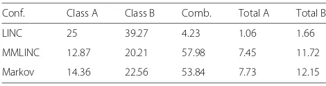
Table 3Estimated efficiency bounds (%) OFDM 1 MHz bandwidth
Conf. Class A Class B Comb. Total A Total B
LINC 25 39.27 4.23 1.06 1.66
MMLINC 12.87 20.21 57.98 7.45 11.72
Markov 14.36 22.56 53.84 7.73 12.15
the classical multiplexing mode and the Markov mode envelopes. Their pdfs have strong peaks in the cmax/2 envelope value, which are clearly outphased LINC sam-ples. According to Fig. 3b, there are strong differences in the balance mode statistics which leads to different performance in terms of efficiency and linearity.
4 Simulation Analysis
The importance of the Markov chain parametersaandb has been shown in previous sections. On the one hand, PAPR can be selected according to the percentage of out-phased signal samples. On the other hand, this allows us to properly set the ratioa/b but not to fix numerical values foraandb. Distortion analysis can be helpful in order to finally choose suitable values which aim at obtain-ing good performance in terms of linearity and efficiency. Markov LINC simulations are carried out to study the per-formance and to compare to the MM-LINC and classical LINC. Firstly, a PA model is extracted from real measure-ments using a polynomial model (PM) with an OFDM signal source. Secondly, an ACPR analysis is addressed using the PA models to draw some conclusions abouta andb independently. Finally, the LINC structure is eval-uated in an ideal scenario (both branches do not have imbalances).
Figures4aand5ashow the measurement and the simple model corresponding to a real power amplifier. Poly-nomial models are a very popular class of behavioral power amplifier mathematical representations for wide-band applications and or high-power amplifiers and are shown to be a good characterization of nonlinear PAs [16–18]. If the baseband input and output are x(t), y(t) respectively, φp is a basis function with terms in the form of|x(t)|px(t),αpare complex coefficients,N is the nonlineary order, the PM:
y(n)=
In this work, the real modeled PA is the CREE CGH40006P, which has 1-dB compression around 29.9 dBm and is measured around 2.6 GHz using multi-carrier modulation with two different signal bandwidths, 1.4 and 5 MHz. Finally, the PM model has been trained up to order 7.
Transition probabilities are the key parameters which may be analyzed to minimize spectral regrowth. Some Monte Carlo simulations have been carried out to study their effects on ACPR and efficiency. Figures 4band5b show that better efficiencies are achieved when the tran-sition probabilitiesaandbare relatively close. Intuitively, if combiner and PA efficiencies would increase/decrease at the same rate, then a 50% would be the optimal value in terms of efficiency and distortion. The effi-ciency rate depends on the bias of the PAs and is dif-ferent from that of the combiner. Thus, the trade-off solution is not exactly at this point but close. As a con-clusion, some optimization algorithm should be carried to choose the accurate proportion between outphas-ing and balanced samples in order to fulfill a standard specification.
In addition, the higher values of transition probabilities, the faster the modes switch (NB,NO, are smaller) due to the time variability of the signals. The Markov sequence multiplies the samples, andaandbmust fulfill the sam-pling theorem. Therefore, the signal bandwidth plays an important role so that the transition probabilities do not cause aliasing in the signal component separation process. Figure 6 shows the simulation results obtained for a LINC structure in three cases, LINC, MM-LINC, and Markov LINC. The signal sources are the previous OFDM signals and are decomposed using the three schemes keeping the same input power. The MM-LINC thresh-old and transition probabilities are set using the PAPR and ACPR studies (γ = 0.18, a = b = 0.01) just to check if the proposed technique works. These values have been chosen so that the output power with both multiplexing schemes were similar in order to have an efficiency which is comparable. Alternatively, those val-ues could have been chosen to provide similar ACPR and then verify if the Markov technique provides bet-ter efficiency. Nevertheless, a proper optimization algo-rithm should be investigated or a utility function should be defined in order to choose the best trade-off accord-ing to the needs and requirements of a specific wireless scenario.
As expected, the Markov MM-LINC outperforms the standard mode multiplexing method because its signals have a better PAPR, leading to identical output power but less adjacent channel interference.
Table 4Estimated efficiency bounds (%) OFDM 5 MHz bandwidth
Conf Class A Class B Comb. Total A Total B
LINC 25 39.27 8.07 2.02 3.17
MMLINC 13.07 20.53 62.03 8.11 12.73
a
b
Fig. 7Experimental setup.aHardware implementation.bEquivalent black-box diagram corresponding to experimental test
Furthermore, efficiency bounds (showed in Tables3and4) have been estimated in both cases, using results from [10,11,14] under the hypothesis that the amplifier could be either class A biased or class B and with an isolated combiner. Actual values will be experimentally evaluated, but this shows that with the proposed values, the Markov method may lead to comparable efficiency values with a better ACPR behavior. The use of class B amplifiers could improve the efficiency but mode multiplexing schemes would be more sensitive to nonlinear effects.
5 Experimental evaluation 5.1 Implementation
Three mode-multiplexing algorithms have been tested on a LINC prototype to verify the real improvement and to find out if the trends predicted through simulations are accurate.
The complete experimental test bench is shown in Fig.7atogether with an equivalent block diagram includ-ing the real RF elements (Fig. 7b). The digital devel-opment platform used for the implementation of signal
component separator, digital signal processes, and the dig-ital I/Q modulator and demodulator consists of a main board (ZedBoard featuring Zynq 7020 All-Programmable SoC) connected to a PC, which controls a high-speed analog module with an integrated RF agile transceiver, the AD-FMCOMMS2-EBZ. It comprises a RF 2 × 2 transceiver with integrated 12-bit DACs and ADCs and has tunable channel bandwidth (from 200 kHz to 56 MHz) and RX gain control. The output signals of the DACs are preamplified and upconverted to a RF frequency of 2. 6 GHz. Finally, two power stages (a ZHL-4240 Minicir-cuits driver and a CGH400006P power amplifier) amplify both signals. The operating input power levels ensure that the driver is working linearly in back-off with the tested OFDM signals. Both branch outputs are com-bined by means of a power combiner (ZN2PD2-50-S+). The experimental evaluation begins with a calibration process, estimating the imbalance in magnitude and phase for each branch of the LINC transmitter. The imbal-ance correction algorithm uses the feedback loop and the RX AD-FMCOMMS2-EBZ input, and only two complex
a
b
Table 5Experimental LINC and mode-multiplexing results BW = 1.4 MHz
BW = 1.4 MHZ Pout (dBm) ACPR (dBc)P(DC,1) P(DC,2) Eff % FoM EVM %
LINC 26.3 29.3 13.32 12.35 1.66 1 2.47
MM-LINC 27.1 18.9 7.84 7.5 3.34 2.01 4.1
Markov 29.1 30.3 10.33 9.07 4.16 2.51 8.7
coefficients (thus, it is only accurate in a narrowband context and not applicable to wideband waveforms). The transmitted signals,ˆs1(n) andˆs2(n) are a corrected ver-sion in amplitudekiand phaseφiof the outphasing signals s1(n)ands2(n)through two complex coefficients
ˆ
s1(n) = k1ejφ1s1(n) ˆ
s2(n) = k2ejφ2s2(n) (31)
Those coefficients are computed by minimizing the ACPR using the Nelder-Mead algorithm which avoids to compute derivatives and can be adaptively performed. Therefore, the ACPR is a function f of the correction coefficients,
ACPR(y)=f(k1,φ1,k2,φ2) (32)
and the optimal solution is
k1opt,φ1opt,k2opt,φ2opt
=arg min ACPRy (33) wherey(n)is an attenuated version at the combiner out-put. Once they are compensated, the signals correspond-ing to the different signal separation component methods are transmitted.
It must be pointed out that simulations do not include either memory effects or imbalances in the whole RF chain; hence, simulated and experimental figures are not directly comparable. Simulations are used in this case for designing the algorithms and the real setup is used for confirming the proposed approach.
In order to ensure that linearity is achieved without decreasing efficiency, we propose to use a figure of merit based on DC power (PDC) and output power (Pout), which are measured using the power supply and a spectrum ana-lyzer (EXA N9010A). The total LINC efficiency (PA and combiner) can be evaluated as
ηLINC=
Pout PDC,1+PDC,2
(34)
where subscripts 1 and 2 denote the DC power used by each power amplifier. This expression is also valid in the case of the mode-multiplexed policies. Therefore, the metric
takes into account the improvement or degradation in efficiency.
5.2 Results
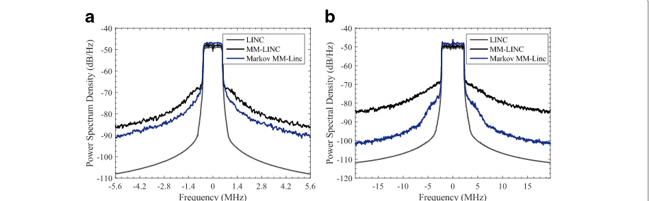
The experimental setup has been tested with the same simulated OFDM signals and a sampling frequency of 61.44 MHz. Figure8shows the power spectral density of the output transmitter signal in a standard LINC, a MM-LINC, and our proposed method. From a qualitative point of view, the standard LINC achieves good ACPR with the lowest output power as Tables5and6show. Better effi-ciency is obtained with a MM-LINC policy, because the output power is increased and DC power is decreased. However, the enhancement in output power is achieved at the same time that nonlinearity effects are increased. ACPR is increased compared to the standard LINC. The novel approach improves global efficiency as well and may provide the maximum output power compared to the other methods (2 dB for the 1.4 MHz signals and 0.9 dB for 5 MHz), with a higher architecture efficiency than the standard LINC. However, like in the MM-LINC policy, the EVM is increased in comparison to the stan-dard LINC. Furthermore, the ACPR is the same than the standard LINC or even is improved 2.9 dB, and the spec-tral regrowth is less severe in the Markov policy if it is compared to the MM-LINC scheme.
Although impairments are not studied in simulations, experimental results show their effects on the 5 MHz OFDM signal. It should require a more robust memory mismatch correction algorithm to improve out-of-band cancellation, and in contrast, Markov MM-LINC wave-forms seem to be less sensitive to RF chain imbalances, as the ACPR is better than in the standard LINC. The Markov-outphased signals do not have such a great signal bandwidth compared to the LINC signals, and therefore, impairments due to memory effects are small in com-parison with the standard LINC and easier out-of band cancellation can be carried out. To sum up, the proposed method can comparatively achieve similar results than the MM-LINC method but with better ACPR, which is one of the characteristics of the reverse MM-LINC.
6 Conclusion
In this work, a novel mode multiplexing method for LINC transmitters is presented, implemented, and ver-ified. A mathematical analysis of the PAPR proves that the new policy behaves better in terms of spectral
Table 6Experimental LINC and mode-multiplexing results BW = 5 MHz
BW = 5 MHz Pout (dBm) ACPR (dBc) P(DC,1) P(DC,2) Eff % FoM EVM %
LINC 28.1 31.9 11.12 11.48 2.86 1 7.05
MM-LINC 28.3 31.4 6.44 6.92 5.06 1.77 9.28
regrowth compared to other proposed multiplexing poli-cies, which has been verified by means of simulation. The experimental LINC transmitter has been imple-mented and tested with OFDM signals, obtaining good performance with low complexity. Experimental results demonstrate that it is possible to reduce the ACPR up to 4.5 dB in a system with a multicarrier modulation without decreasing the output mean power, compared to standard MM methods, and improving efficiency by approximately 2 compared to the classical LINC technique.
Appendix
According to (14), PAPR derivation requires to compute the quantity
Pav=E|sn|2=
ρ2f
|s|(ρ)dρ (36)
The MM-LINC PAPR uses the density given in (23). Then
The Markov-multiplexed LINC PAPR uses the density given in (28). Then
ACPR: Adjacent channel power ratio; ADC: Analog digital converter; DAC: Digital analog converter; DSP: Digital signal processor; EER: Envelope elimination and restoration; FBMC: Filtered band multicarrier; FPGA: Field
programmable gate array; GFDM: Generalized frequency division multiplexing; LINC: Linear amplification with non-linear components; LTE: Long-term evolution; MILC: Modified implementation of LINC; MM-LINC: Mode-multiplexing LINC; OFDM: Orthogonal frequency Mode-multiplexing modulation; PA: Power amplifier; PAPR: Peak-to-average power ratio; PC : Personal computer; PDF: Probability density function; QPSK: Quadrature phase-shift keying; RAM: Random access memory; RF: Randiofrequency; RM-LINC: Reverse mode LINC; ROM: Read-only memory; SCS: Signal component separator
Funding
This work was supported by the spanish Government (Project
TEC2014-58341-C4-2-R from MICINN and FEDER) and the Aragón Government and FSE (GCM T97).
Authors’ contributions
PLC contributed to the measurements, result analysis, and article writing. PG-D contributed to the result analysis and article writing. JdeM contributed to the result analysis and article writing. AV contributed to the article writing. All authors read and approved the final manuscript.
Competing interests
The authors declare that they have no competing interests.
Publisher’s Note
Springer Nature remains neutral with regard to jurisdictional claims in published maps and institutional affiliations.
Received: 31 May 2017 Accepted: 22 January 2018
References
1. PM Lavrador, TR Cunha, PM Cabral, JC Pedro, The linearity efficiency compromise. IEEE Microw. Mag.11(5), 44–58 (2010)
2. A Birafane, M El-Asmar, AB Kouki, M Helaoui, FM Ghannouchy, Analyzing LINC systems. IEEE Microw. Mag.11(5), 59–71 (2010)
3. B Kim, J Moon, I Kim, Efficiently Amplified. IEEE Microw. Mag.11(5), 87–99 (2010)
4. M Helaoui, FM Ghannouchi, Linearization of power amplifiers using the reverse MM-LINC technique. IEEE Trans. Circuits Syst. II, Exp. Briefs.57(1), 6–10 (2010)
5. M Helaoui, S Boumaiza, FM Ghannouchi, AB Kouki, A Ghazel, A new mode-multiplexing LINC architecture to boost the efficiency of WiMAX up-link transmitters. IEEE Trans. Microw. Theory Techniques.55(2), 248–253 (2007) 6. P Garcia-Ducar, A Ortega, J de Mingo, A Valdovinos, Nonlinear distortion
cancellation using LINC transmitters in OFDM system. IEEE Trans. Broadcast.51(1), 84–93 (2005)
7. P Garcia-Ducar, J de Mingo, PL Carro, A Valdovinos, Design and experimental evaluation of a LINC transmitter for OFDM systems. IEEE Trans. Wirel. Commun.9(10), 2983–2987 (2010)
8. T Hwanq, K Azadet, RS Wilson, J Lin, Linearization and imbalance correction techniques for broadband outphasing power amplifiers. IEEE Trans. Microw. Theory Tech.63(7), 248–253 (2015)
9. AF Aref, TM Hone, R Negra, A study of the impact of delay mismatch on linearity of outphasing transmitters. IEEE Trans. Circ. Syst. I.62(1), 254–262 (2015)
10. FH Raab, Efficiency of outphasing RF power-amplifier systems. IEEE Trans. Commun.33(10), 1094–1099 (1985)
11. T Hwanq, K Azadet, RS Wilson, J Lin, On the linearity and efficiency of outphasing microwave amplifiers. IEEE Trans. Microw. Theory Tech.52(7), 1702–1708 (2004)
12. PL Gilabert, A Cesari, G Montoro, E Bertrand, J Dilhac, Multi-lookup table FPGA implementation of an adaptive digital predistorter for linearizing RF power amplifiers with memory effects. IEEE Trans. Microw. Theory Tech.
56(2), 372–384 (2008)
13. H Yang, M Alouini, Markov chains and performance comparison of switched diversity systems. IEEE Trans. Commun.52(7), 1113–1125 (2004) 14. H Ochiai, H imai, On the distribution of the peak-to-average power ratio
in OFDM signals. IEEE Trans. Commun.49(2), 282–289 (2001) 15. H Ochiai, An analysis of band-limited communication systems from
amplifier efficiency and distortion perspective. IEEE Trans. Commun.
16. DR Morgan, Z Ma, J Kim, MG Zierdt, J Pastalan, A generalized memory polynomial model for digital predistortion of RF power amplifiers. IEEE Trans. Microw. Theory Tech.54(10), 3852–3860 (2006)
17. K Hyunchul, JS Kenney, Behavioral modeling of nonlinear RF power amplifiers considering memory effects. IEEE Trans. Microw. Theory Tech.
51(12), 2495–2504 (2003)