Interaction of Alfven waves with a turbulent layer
V. Pilipenko1, E. Fedorov2, and M. J. Engebretson3
1Space Research Institute, 84/32 Profsojuznaya, Moscow 117997, Russia 2Institute of the Physics of the Earth, 10 B. Gruzinskaya, Moscow 123995, Russia
3Augsburg College, 2211 Riverside Ave., Minneapolis, MN 55454
(Received March 6, 2008; Revised June 6, 2008; Accepted June 23, 2008; Online published October 15, 2008)
We consider the interaction of Alfven waves with a resistive turbulent layer with anomalous conductivity. High-frequency turbulence causes the occurrence of both field-aligned and transverse resistivity. The correct dispersion relationship for Alfven waves in a turbulent medium with anisotropic conductivities has been derived. Alfven waves may partially reflect from a resistive layer, be absorbed in it, or be transmitted through it. When field-aligned resistivity dominates, the relative effectiveness of these processes critically depends on the wave transverse scale. For a thin layer as compared with the wave field-aligned length, the characteristic parameter that controls the effectiveness of the wave interaction with a layer is the resistive Alfven scaleλA, determined by the field-aligned resistance and Alfven velocity above the layer. Comparison of energy losses estimated from analytical relationships for a “thin” layer and from numerical calculations for a finite width layer shows that the thin layer approximation provides a reasonable estimate over a wide range of wave scales, not only very small. Estimation of the effective damping scale of the Pc1 waves in a turbulent cusp shows that the cusp proper cannot be a conduit of Pc1 wave energy from the magnetosheath to the ground. The “thin” layer model has been applied to the interpretation of the results of early studies of transient ULF wave (Pi2 pulsations) damping during substorm onset, which showed that the damping rate increased for accompanying magnetic bays stronger than∼100 nT. Our estimates confirm that this additional damping can be caused by the occurrence of anomalous transverse resistance when magnetospheric current exceeds the threshold necessary for the excitation of high-frequency plasma turbulence.
Key words:Alfven waves, ULF pulsations, anomalous resistivity, plasma turbulence.
1.
Introduction
Alfven waves play an important role in dynamic pro-cesses in space plasma by transporting without geometric attenuation non-stationary field-aligned currents to consid-erable distances. Space plasma is often turbulent, so scat-tering of particles by turbulent noise becomes more efficient than Coulomb collisions. Such anomalous collisions of par-ticles with turbulent noise result in the occurrence of finite anomalous plasma resistivity (Galeev and Sagdeev, 1973; Liperovsky and Pudovkin, 1983) and formation of turbulent layers (TL) in a space plasma.
The problem considered here is just one aspect of the more fundamental problem of MHD wave propagation through a turbulent plasma. This latter, still not resolved problem is of key importance for near-Earth space physics, in particular for penetration of ULF waves through the mag-netosheath or auroral plasma, propagation of ULF bursts and transients along the magnetotail, etc.
For the problem of energy transfer in space the interac-tion of Alfven waves with a region of turbulent plasma with finite conductivity due to anomalous collisions is of great importance. The basic notions about Alfven wave inter-action with a turbulent layer (TL) with anomalous
field-Copyright cThe Society of Geomagnetism and Earth, Planetary and Space Sci-ences (SGEPSS); The Seismological Society of Japan; The Volcanological Society of Japan; The Geodetic Society of Japan; The Japanese Society for Planetary Sci-ences; TERRAPUB.
aligned resistance were formulated by Lysak and Dum (1983), who showed that waves can partially penetrate a layer, be absorbed in it, and reflect from it. The relative rate of these processes turned out to be dependent on the transverse wave scale. Later on this model was augmented by Trakhtenhertz and Feldstein (1985), who indicated that the occurrence of anomalous collisions should modify not only the field-aligned conductivity, but transverse (Peder-sen) conductivity as well, and substantially enhance the wave absorption in a TL.
Quite often, e.g. at auroral latitudes, the high-frequency turbulence is confined in a narrow region, where the thresh-old for current instability is minimal (Kindel and Kennel, 1971). The width of such a layer with anomalous resistivity might be small as compared with the field-aligned scale of low-frequency Alfven waves. Therefore, for the description of wave-layer interaction in such a case the thin layer ap-proximation may be used. This apap-proximation enables one to obtain simpler analytical relationships and to reveal the physical parameters that control this interaction. The prob-lem of Alfven wave interaction with a TL has much in com-mon with the problem of Alfven wave transmission though a layer with a field-aligned potential drop. The first mech-anism is caused by local resistivity due to anomalous colli-sions (Lysak and Carlson, 1981), whereas the latter mecha-nism is related to the non-resistive potential drop caused by mirror forces in a magnetic flux tube (Lyons, 1980; Vogt
and Haerendel, 1998). The nonlocal dissipation associ-ated with a field-aligned potential drop provides a scale-dependent coupling between the magnetosphere and iono-sphere. The magnetospheric flow profile may undergo sub-stantial redistribution during its evolution as a direct con-sequence of the field-aligned potential drop (Lotko et al., 1987). The studies of Lyons (1980), Vogt and Haerendel (1998), and Vogt (2002) revealed the key spatial parameters of such a coupling mechanism: the resistive scaleλPand λA, determined by the field-aligned conductance of a flux tube, Pedersen conductance of the ionosphere, and Alfven velocity of the magnetosphere. Though the mechanisms of non-resistive field-aligned potential drop and anomalous resistance are physically different, there is a mathematical similarity between these models. Therefore, in this paper we apply for the description of the Alfven wave interac-tion with a TL with anomalous longitudinal and transverse conductivities an approach similar to the one which has been applied for the consideration of Alfven wave interac-tion with a plasma layer with non-local Ohm’s law for a field-aligned current (Fedorovet al., 2001). The theoretical model developed will be applied to the consideration of the role of Alfven wave damping in turbulent regions that occur in the near-Earth space environment.
2.
Model of Alfven Wave Interaction with a TL
We consider interaction of Alfven waves with a flat TL with widthh and complex transverseσ⊥ and field-aligned σconductivities. The real parts of these conductivities are caused by the occurrence of effective frequencies of elec-tron, νe, and ion, νi, collective collisions with turbulent noise. It is assumed that microturbulence is supported by external sources, and is not created by an Alfven wave it-self. Otherwise, the wave interaction with a self-generated anomalous resistance layer may be accompanied by a num-ber of specific effects, e.g. limitation of the field-aligned current transmitted by a wave (Mazuret al., 2007).
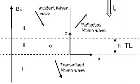
The model considered here is depicted in Fig. 1. An external straight magnetic field B0 is normal to the layer, and coincides with theZ-axis of an orthogonal coordinate system{x, y, z}. The planez=0 is the interface between the TL (n = 2) and lower semi-space (n = 1), whereas
the planez =h is the interface with the upper semi-space (n = 3). In each plasma layer (n = 1,2,3) the Alfven
Incident Alfven wave
h
TL
z
x
I
j0 0
B
II
III Reflected Alfven wave
Transmitted Alfven wave
Fig. 1. A sketch of the model of Alfven wave interaction with a turbulent layer (TL).
velocityVAnand wave conductanceAn =(μ0VAn)−1 are
constant.
2.1 Alfven waves in a resistive medium
Wave disturbances are presented as a sum of harmonics
∝exp(−iωt+i k⊥x), wherek⊥is the transverse wave num-ber. From Maxwell’s equations and Ohm’s lawj= ˆσEthe equations for Alfven waves in a medium with transverse σ⊥(ω)and parallel (field-aligned)σ(ω) complex
conduc-tivities follow. The possible coupling with the fast compres-sional mode due to the Hall conductance may be noticeable only for waves with sufficiently large transverse scales, be-yond the scales considered here (see estimates in Yagovaet al.(1999)). In this case Ohm’s law becomes
j⊥=σ⊥E⊥, j=σE (1)
Maxwell’s equations reduce to
∂z
Ex
By
= ˆT
Ex
By
, Tˆ =
0 iω−k⊥2/μ0σ −μ0σ⊥ 0
(2) In a homogeneous medium the coefficients of (2) are coordinate-independent and a dispersion equation can be derived as follows
det
ˆ
T−i k1
=0 (3)
where 1 is the unit 2× 2 matrix, and k = kz is the
field-aligned component of the wave numberk. From the dispersion equation (3) we obtain
iωμ0= k2
σ⊥(ω)+ k2
⊥
σ(ω) (4)
Equation (4) makes sense only if the frequency dependence of both conductivities is explicitly indicated.
In the case of resistive MHD one has
j⊥=σ0(E⊥+v×B0) , j=σ0E (5)
wherevis the plasma velocity. The linearized momentum equation of the MHD system gives
v⊥= iμ0V
2 A
ωB02 (j⊥×B0) (6)
whereVAis the Alfven velocity. Substitution of (6) into (5) provides the possibility to deduce an effective conductivity tensorσ (ω)ˆ as follows
σ−1
⊥ (ω)=σ0−1− μ0VA2
iω , σ=σ0 (7)
In an medium with isotropic conductivityσ0 from (4) and (7) the widely used dispersion equation for Alfven waves in a resistive medium follows (Tikhonchuk and Bychenkov, 1995; Senatorov, 1996)
ω2−
k2VA2+k2+k2⊥ iω
μ0σ0 =
0 (8)
ions, and plasmons (neutral quasi-particles). We consider neutral quasi-particles as motionless, though at very low frequencies a dragging of plasmons by oscillating ions is possible (Liperovsky and Martjanov, 1973). The transverse conductivity of such a medium is composed of electron and ion conductivities σ⊥ = σ⊥(e) +σ⊥(i). Rather complicated relationships for the conductivity tensor can be reduced for low-frequency waves (ωi) to the following
σ⊥(ω)σP− iω
μ0V˜A2
, σ(ω)−1μ0λ2e(νe−iω) (9)
The complex transverse conductivityσ⊥is composed of the contributions from the static Pedersen conductivityσP and polarization current. HereV˜2
A =VA2 the Alfven velocity modified by collisions, λe = c/ωpeis the plasma electron inertial scale, and ωpe = N e2/meε0 is the plasma frequency. Further on, for simplicity we neglect the distinction betweenVAandV˜A. Commonly, the contribution of electron inertia in field-aligned conductivity can be omitted, that is,
σσ0=ε0ω2peνe−1=
μ0λ2eνe −1
(10)
Substitution of (9) into (4) results in the generalized disper-sion equation for Alfven waves in a turbulent medium
k2=1+k2⊥λ2e kA2 +iωμ0σP
Equation (11) coincides with the equation from Lysak and Dum (1983) in the limiting caseσP → 0. The gas of plas-mons is assumed to be like neutral particles upon collisions with electrons and ions in a weakly-collisional plasma. The static field-aligned conductivity (10) is provided by electron collisions, whereas the Pedersen conductivity is supported by ions and electrons, and is determined by the formula
σP= control the frozen-in conditions for electrons and ions, and eandiare their cyclotron frequencies.
Here we introduce the frequencies
ν1=μ0VA2σP= Substituting (13) into (11) transforms the dispersion equa-tion to the following form
k2
The wave resistance of the resistive TL is determined by the following relationship:
ZA=A−1= − i k
σ⊥ (15)
In the ideal MHD approximation, when σP → 0 and
|σ| → ∞, so ν1 → 0, ν2 → 0, λe → 0, and the
dispersion equation (14) gives k = kA = ω/VA and ZA = A−1 = μ0VA. Such a medium may be character-ized by the plasma dielectric permeabilityε⊥ = (c/VA)2. The transverse conductivity is determined by the polariza-tion current σ⊥ = −iω/μ0VA2, whereas the field-aligned resistance vanishes.
In the quasi-static case, when ω ν1ν2/(ν1+ν2) ≤ (ν1 +ν2)/4, the first and the second terms in the right-hand side of (14) may be neglected, so this equation de-scribes the attenuation of an electromagnetic field in an anisotropically-conductive medium with the damping scale
κ=Imk
We introduce the effective skin-depths, δ and δP, deter-mined by the field-aligned and transverse conductivities, correspondingly:
When transverse wave numbers and frequencies are not very low, that isk⊥ (δPδkA)−1andkAδP−1, orν1 ν2 andν1 ω, the generalized dispersion equation (14) reduces to the following
k2=1+k⊥2λ2ekA2
This equation, with account for (13), may be written as follows
1+k⊥2λ2eω2−k2VA2+k2⊥ iω
μ0σ0
=0 (18)
The dispersion equation obtained is somewhat different from the commonly used (8). The longitudinal wave num-ber may be found from the following relationship stemming from (14) wave spatial decay upon propagation can be estimated from the following relationship, comprising both field-aligned and transverse resistances These conditions may be written in the alternative form for the strongly magnetized electrons and ions, i.e.re1 and ri1, andk⊥λe1, as followsνi+(me/mi)νeω, and k2
⊥λ2eνeω.
Further we will see that the critical transverse scales of Alfven wave interaction with TL are much larger thanλe, so the correction due to electron inertia may be neglected,
2.2 Alfven waves in a multi-layered system
The field-aligned componentsk of wave vectors in the layers k1, k2, and k3 are determined by relevant disper-sion equations. In the upper and bottom semi-planesk1 = ω/VA1, andk3 =ω/VA3, whereas the wave number in the TL,k2, is determined by (14) for an Alfven wave in a resis-tive medium.
In each of the homogeneous layers the solution of Eq. (2) may be presented in the following form:
By= B1e−i k1z
HereRandR2are the coefficients of wave reflection from the upper and lower TL boundary, correspondingly, andB1, B2, andB3are amplitude coefficients.
Each of the plasma semi-spaces (n = 1,3) has a wave resistance ZAn = A−n1 = ±μ0Ex±/By±, where the±sign
corresponds to upward/downward propagating waves. The continuity of the tangential component of the wave electric and magnetic fields at the interface between the layers (z=
0) results in the boundary condition
Ex= −μ−01ZA1By (22)
Substitution of (21) into (22) provides a known expression for the coefficient of Alfven wave reflection from a bound-ary between two plasma layers
R2=
ZA2−ZA1 ZA2+ZA1
(23)
However, in a multi-layered system a similar formula does not work at the interfacez=hand should be modified. 2.3 Wave reflection from a finite-width layer
The surface input impedance Zin at the upper boundary of the resistive layer (z=h) is determined by the recurrent equations which coupleZinand the impedance at the lower boundary (z=0) as follows
The coefficient R of the Alfven wave reflection from the TL is related to the surface impedance Zin by the known relation
R= ZA3−Zin ZA3+Zin
(25)
Substituting (24) into (25) we get
R= A1−A3+
Now we find the coefficient of wave transmission through the layer. From the continuity of magnetic field atz=hand
z=0 it follows that
Combining (27), the transmission coefficient T = B1/B3 can be found. Substituting in (27) the relationships (23) and (25) for the reflection coefficients R2 and R, we get after simple algebra
2.4 Wave reflection from a thin layer
We define a TL as an “optically thin” (or just thin) layer when |k2h| 1. This condition can be more explicitly expressed in two cases. For large transverse wave numbers, satisfying the inequality (ν1 +ν2) ω, from (11) the approximate relation (16) follows. Then, the condition of a thin layer has the form
|k⊥λP| 1 (30)
Here we have introduced the dissipative scale λP =
σσ⊥2h = |Q⊥2|, where Q = h/σ0 is the field-aligned integrated resistance of the layer.
When transverse wave numbers are so small thatν2ν1 andν2 ω, the condition of the thin layer approximation is somewhat different. In this case the wave dispersion equation in a TL givesk22 iωμ0σ⊥. For low-frequency waves withω ν1 we haveσ⊥ σP. As a result, a TL may be considered as “thin” when
hδP (31)
In this limit of large-scale disturbances (k⊥→0) the reflec-tion and transmission coefficients are weakly dependent on the transverse wave numbers, and are as follows
RR0 =
Here we have introduced the normalized Alfven conduc-tances
When the condition (30) of the thin layer approximation is valid, the coefficient of wave reflection from a layer (26) reduces to the following
qm=
In (33) the dimensionless transverse wave number k⊥ = k⊥λAhas been introduced.
The parameter λA = (A3Q)1/2 is determined by the altitude-integrated field-aligned resistance Q and the Alfven velocity above the TL. According to its physical sense, this parameter is the transverse scale when the field-aligned column resistance matches the Alfven wave resis-tanceA−1. The previously introduced parameter, the resis-tive lengthλP, is the transverse wave scale when the scale of wave penetration into a TL with conductivityσmatches the layer widthh. As one will see further, the key parame-ter of the Alfven wave inparame-teraction with a thin TL is the ratio betweenλAand the wave transverse scale, namelyk⊥λA. At the same time, the ratio between the parameterλP and k⊥−1 more adequately characterizes the wave dissipation in a thin TL. These two parameters,λPandλA, were first in-troduced as the resistive scale (Lyons, 1980) and transient length scale (Vogt and Haerendel, 1998; Vogt, 2002) of magnetosphere-ionosphere coupling, in studies of the math-ematically similar problem of the Alfven wave interaction with the non-resistive potential drop region.
From (33) it follows that if the Alfven wave transverse scalek−⊥1matches the critical value
L∗⊥=λA Alfven wave resistanceA3, and the reflection coefficient from a thin TL vanishes, R = 0. Thus, the dependence
Rk⊥(33) should change sign at the criticalk∗⊥=1/L∗⊥. Now we find the coefficient of the wave transmission through a thin layer. Decomposing cos(k2h) andG(k2h) into Taylor series, and neglecting in (29) terms of the order of(k2h)3, we obtain
2.5 Alfven wave energy losses in a TL
Let S(i), S(r), and S(t) be densities of the energy fluxes carried by incident, reflected, and transmitted waves, re-spectively. The energy losses of Alfven waves in a resistive layer are determined as follows
J=S(i)−S(r)−S(t) (38)
The energy flux densities in incident, reflected, and trans-mitted Alfven waves may be presented via the amplitude of Alfven waves in the magnetosphereB3as follows
S(i)= VA3
The energy lossαin a TL, normalized to the energy flux of incident waves, can be found from (38) and (39)
α= J
S(i) =1− |R| 2−VA1
VA3|
T|2 (40)
2.5.1 Finite-width TL In a finite-width TL with thicknesshthe energy absorption rate comprises two terms
q⊥andq, where
From (21) we have
Ex = −
whereB2andB3are related by (27). Substituting (42) into (41), and taking into account (40), we obtain the relation-ship for the normalized energy loss due to the transverse and field-aligned conductivities, as follows
α⊥= q⊥ relationship for K can be transformed, using (26), into the following
2.5.2 Thin TL In the thin layer approximation modi-fied expressions for coefficientsI1,2(k2h)andK(k2h)may be found in Fedorovet al.(2007). Using them, from (43) it is possible to find the “transverse” and “field-aligned” en-ergy losses in the thin layer approximation
Coefficientsα⊥0andα0in (47) determine the energy losses for waves with large scales, when k⊥ → 0, and are as follows
α⊥0=
4PA3
|T|2
, α0= 42
A1
|T|2
(49)
3.
Numerical and Analytical Estimates
Here we provide the results of both numerical calcula-tions with the exact formula and estimates using the thin layer approximation for several models, based on published parameters of near-Earth space and turbulence.
3.1 Models of a TL
To validate the significance of the effects considered here we provide numerical results for some models of anomalous conductivity presented in the literature. To highlight the ef-fect of anomalous resistance in a layer, we make the Alfven velocity the same at all altitudes. This way we exclude an additional wave reflection atVAjumps.
The effective frequency of particle-plasmon collisions in general is a function of the turbulence spectral powerWand plasma parameters. Estimating this frequency is a difficult problem, which should be solved separately for each partic-ular turbulence type. Precise estimates demand knowledge of turbulence type, its spatial spectra, dominating non-linear saturation mechanism, etc. Many of these parameters are not easily observable, so the estimates provided in the lit-erature vary over a wide range. Assuming that collision frequencies are known from the solution of a relevant ki-netic problem, one may use the developed relationships to validate the Alfven wave transmission through a particular TL. For that, one has to replace in the plasma conductivities (10) and (12) the frequencies of collision of charged parti-cles with neutrals by the collective particle-plasmon colli-sion frequencies.
For ion-acoustic turbulence an estimate of the maximal collision frequencies has been shown (Liperovsky and Pu-dovkin, 1983) to be
νeωpe(W/nT), νiωpi(W/nT)2 (50) whereW/nT is the ratio between the energy densities of turbulent noise and background plasma. However, the ion-acoustic turbulence can exist in a highly non-isothermal plasma only when Te Ti. In other situations the elec-trostatic ion-cyclotron instability dominates. This instabil-ity saturates at a level which provides νe = (0.2−1)i (Ionson, 1976; Hudsonet al., 1978).
The interaction of Alfven waves (periodT =100 s) with a TL has been calculated for several models with differ-ent types of turbulence. The parameters of the background plasma have been chosen to correspond to typical values in the auroral cavity of the upper ionosphere: N =103cm−3, B = 1.45·103 nT. These values correspond to Alfven velocities VA1 = VA2 = 103 km/s, and wave conduc-tanceA=0.8 Ohm−1. Characteristic frequencies in such plasma are ωpe 1.79·106 s−1, ωpi 4.17·104 s−1, e2.55·105s−1, andi1.39·102s−1. The electron inertial scale isλe170 m.
To validate the thin layer approximation we have made calculations for two model layers with parameters adapted from (Trakhtenhertz and Feldstein, 1985):
TF-1: h = 30 km, νe = 103 s−1,νi =
√
me/miνe = 23 s−1;
TF-2: h = 100 km,νe = 102s−1,νi =
√
me/miνe = 2.3 s−1.
For the TF-1 and TF-2 models the anomalous field-aligned conductivities σ0 = 2.8 × 10⁻²Ohm−1 · m−1 and 2.8×10⁻¹Ohm−1·m−1, resistances Q = h/σ
106Ohm·m2and 0.35×10⁶Ohm·m2, respectively. The Pedersen conductivityσP = 1.8·10−5Ohm−1·m−1 and 0.19 ·10−5Ohm−1 ·m−1, Pedersen conductances
P = 0.55 Ohm−1 and 0.19 Ohm−1, the Alfven resistive scales λA0.9 km and 0.5 km, dissipative scalesλP0.76 km and 0.26 km, respectively.
Further, the absorption of Alfven waves in a TL has been calculated for two characteristic types of high-frequency plasma turbulence:
Model S: A layer with ion-acoustic turbulence. Anoma-lous collision frequencies are estimated from the relation-ship of weak turbulence theory (50) assuming W/nT
10−3, andh =103km. A feature of this model is a strong contrast (∼4·104) between the electronν
eand ionνi colli-sion frequencies.
Model C: A layer with ion-cyclotron turbulence. Anomalous collision frequencies are estimated as νe 0.7i,νi=0.1νe, andh =103km. In this model the elec-tron and ion collision frequencies differ by only an order of magnitude.
3.2 Reflection and transmission coefficients
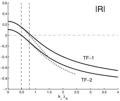
The dependence of the reflection coefficient R on nor-malized transverse wave numberk⊥λAwith account of both conductivities is shown in Fig. 2. Here and further the cal-culations made with the exact formula are denoted by solid lines, and calculations in the thin layer approximation are shown by dotted lines. The model code is indicated near appropriate curves.
The most prominent feature of the reflection coefficient is the change of its sign at certaink⊥ ∼0.2–0.8, depending on the model. The vertical dashed lines denote the valuesk⊥∗ =
Fig. 2. The dependence of the reflection coefficient Ron normalized transverse wave number k⊥λA with account of both transverse and
Fig. 3. The scale dependence of the transmission coefficientT(k⊥λA)
according to exact (solid lines) and approximate (dashed lines) relation-ships for the TF-1 and TF-2 models.
1/L∗⊥ which correspond to critical scales when R should change sign in the thin layer approximation according to (36). For the models TF-1 and TF-2 the conditionL∗⊥≥λP is valid, and the relationship (36) gives a correct estimate of such criticalk⊥. Large-scale Alfven waves (k⊥→0) reflect from a resistive layer as from a conductor R >0, whereas small-scale waves (k⊥ → ∞) reflect as from an insulator, that is R → −1 whenk⊥ λ−P1. Thus, both large-scale and small-scale waves effectively reflect from a TL.
Figure 3 shows the dependence of the transmission co-efficient T on k⊥λA. The coefficient T decreases mono-tonically with increase ofk⊥ fromT0 atk⊥ = 0, and
fur-ther approaches exponentially 0 as k⊥λP → ∞. Indeed, from (29) for largek⊥λP the asymptotic estimate follows T 4(P/A3)(k⊥λP)−1exp(−k⊥λP). Thus, at largek⊥
the energy of incident waves nearly totally converts into the energy of reflected waves.
The comparison of calculation results in the thin layer approximation (dotted lines in Figs. 2–3) and with the com-plete formula for a finite width layer (solid lines) shows that the approximation works well at scalesk⊥λA ≤1 for both models.
3.3 Energy losses in a TL
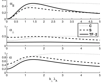
The dependence of energy losses in a layer with anoma-lous conductivity on the transverse wave number for mod-els TF-2, S, and C is shown in Fig. 4. Separate energy losses due to field-aligned α and transverse α⊥ conduc-tivities have been calculated from (43). The total energy lossesαhave been calculated using formula (40), in which the exact coefficients of reflection and transmission are de-termined from (26, 29), and the coefficients in the thin layer approximation are derived from (33, 37).
For all TL models considered the energy losses are max-imal at wave scalesk⊥ ∼ λ−A1. The part of energy losses α⊥k⊥due to transverse resistance weakly depends on the wave scale (middle panel in Fig. 4). In contrast, the part αk⊥reaches peak values atk⊥ 1.4 (upper panel in
Fig. 4). This peak is responsible for the maximum occur-rence in the dependence of total energy losses on wave num-bersαk⊥(bottom panel).
Fig. 4. Dependence of energy losses due to the field-alignedα, transverse α⊥, and totalαTL resistance on the normalized transverse wave number
k⊥for the TF-2, S, and C models.
Thus, wave energy losses are determined by the trans-verse resistance for large-scale disturbances, k⊥λA 1. For small-scale disturbancesk⊥λA 1 both mechanisms contribute at a similar rate. For intermediate wave scales,
k⊥ ∼ λ−A1, the energy losses are mostly determined by the field-aligned resistance.
4.
Geophysical Consequences
4.1 Pc1 waves in the vicinity of the dayside cusp Many studies have proposed the cusp region as a likely source of some of the Pc1-2 waves observed at high lati-tudes on the ground. Intense broadband wave activity in the Pc1-2 band is often reported by low- and mid-altitude satellites (e.g., Erlandsonet al., 1988). Polar satellite ob-servations (Leet al., 2001) showed that narrowband waves at frequencies ∼0.2–3 Hz are a permanent feature in the vicinity of the polar cusp. These waves have been found in the magnetosphere adjacent to the cusp (both poleward and equatorward of the cusp) and in the cusp itself. The occurrence of waves is coincident with the magnetic field depression associated with enhanced plasma density indi-cating the entry of the magnetosheath plasma into the cusp, which suggests that the waves are generated in this region by the precipitating magnetosheath plasma. The polariza-tion and propagapolariza-tion angles of the waves are highly vari-able, whereas energy flux is mostly guided along the back-ground magnetic field. The wave frequencies are generally controlled by the localB0strength, which strongly suggests that these waves are generated locally and absorbed in the near vicinity of the generation region.
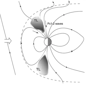
parti-Fig. 5. Sketch of possible Pc1-2 wave propagation paths in the vicinity of the cusp. The cusp proper has been depicted as a TL.
cle observations from the Polar satellite and from ground magnetometers that confirm the presence of the “mantle” waves and characterize the ion distributions associated with them. In-situ particle observations appear to confirm the generation mechanism suggested by Dyrudet al. (1997), that cusp particles mirroring at low altitudes and then trav-eling outward in the plasma mantle poleward of the cusp are the source of the free energy for these waves. The Po-lar particle data showed upward ion fluxes coincident with each mantle wave intensification, and in association with a downward Poynting vector. In contrast, the Poynting vector associated with the intense, broadband ULF activity in the cusp shows mixed direction. This is consistent with the ap-parent lack of a “cusp signature” in ground magnetometer observations in the Pc1-2 frequency range.
The inability of Pc1-2 waves to propagate through the cusp region may be related to enhanced wave absorption in highly turbulent cusp plasma, as illustrated in Fig. 5. Obser-vations on OGO-5 (Frederickset al., 1973) showed that the low altitude cusp (altitudes from 1Reto 3.2Re) is filled with intense (E 9×10⁻²V/m) high-frequency electrostatic turbulence. The mechanism of this turbulence is proba-bly ion-acoustic or Bunemann instabilities driven by intense field-aligned current (typically, j2×10−5A/m2) inside the cusp. This turbulence should provide anomalous sionless resistivity, where the frequency of effective colli-sions of electrons with electrostatic modes can be estimated from (50). For the above parameters, the collisionless re-sistivity in the low-altitude cusp isρ 8 Ohm·m, which produces a field-aligned potential drop at a distance along a field lineS 1.3×10⁷m of as much as j
ρS
2 kV.
For qualitative estimates the relationship (20) from the theory of Alfven wave propagation via a turbulent infi-nite homogeneous medium can be applied. To model the mid-altitude cusp we assume the following plasma and wave parameters: f = 1 Hz, VA = 103 km/s with N = 103 cm−1 and B
0 = 1.4 ×10³ nT. The corre-sponding characteristic plasma frequencies and scales are e 2.6 ×10⁵ s−1, ωpe 1.8 ×10⁶ s−1, and λe 170 m. The measured anomalous field-aligned resistivity
ρ0=8 Ohm−1·m−1should correspond to an electron col-lision frequencyνe=ρ0/
μ0λ2e
2.3·102s−1. Assum-ing that anomalous collisions are similar to charged parti-cle collisions with neutral partiparti-cles, one may suppose that νi=
√
me/miνe5.3 s−1. From these estimates it follows that σP 4.3 ×10⁻⁶ Ohm−1·m−1, andδP 240 km. The expected spatial damping rate isκ 0.25·10−2km−1, andkA/κ 2.5, thus indicating that the amplitude of such waves should decrease by a factor ofein a distance of about 0.4 wavelengths. The damping owing to field-aligned re-sistance is small, kA/κ 104, for transverse wave scales k−⊥1∼102km, and the main contribution is provided by the transverse resistivity.
Our model thus predicts that the occurrence of electro-static turbulence in the cusp causes substantial damping of Alfven waves in the cusp, consistent with the Pc1-2 obser-vational studies reviewed above. Surely, alternative wave absorption mechanisms also might be operative in the cusp region, such as Landau damping due to the resonant wave-particle interaction in the high beta plasma of the cusp, but their consideration is beyond the topic of this paper. These mechanisms may be especially important when the damp-ing due to the anomalous resistance become ineffective, e.g. for a large transverse wave scales.
4.2 Observations of nonlinear damping of Pi2 pulsa-tions
According to the traditional point of view, Pi2 pul-sations are transient oscillatory processes stimulated by substorm onset. Therefore, Pi2 waveforms are com-monly modeled with a linear damped oscillatory function
∝exp(−γt)cos(ωt + ϕ), where the frequency ω is the eigenfrequency of field line oscillations, and the damping rate γ is determined by the dissipation in the night side ionosphere. However, “classical” oscillations of this kind are very rare, and may be observed at low or middle lati-tudes only. At auroral latilati-tudes, Pi2 bursts have complicated waveforms indicating that they are composed of contribu-tions from several nearly simultaneous sources.
We’d like to notice that linear damping as predicted by modeling an exponential function is very rarely observed. Among the large variety of observed wave forms the fol-lowing kind may be selected—a rapid damping of the in-tense part of a signal and a slower damping of the weaker part of a signal. Examples of such non-linear Pi2 damping detected on the IMAGE array on Sep. 25, 2001 are shown in Fig. 6. This example shows that small-amplitude Pi2 damp gradually, while the intense Pi2 pulse damps much faster, right after the first excursion. By and large, this kind of a signal looks like the stalling of an oscillatory process un-der large amplitude conditions. In other words, the mag-netospheric Alfven resonator (MAR) turns out to be highly over-damped under large amplitude Pi2 conditions.
Fig. 6. Examples of Pi2 signals (Hcomponent) with a sudden drop of amplitude, recorded at Kilpisjarvi, a station of the IMAGE array, on 10/01/2001 (day 275), 20–23 UT: raw data (left panel), and band-filtered 7–25 mHz magnetogram (right-hand panel).
magnetic disturbances the Pi2 damping rate acquired an ad-ditional componentγ∗, such thatγ →γ+γ∗. It was sup-posed that this additional non-linear damping mechanism is related to the onset of plasma turbulence and anomalous collisions, when magnetospheric field-aligned currents ex-ceed thresholds necessary for the excitation of anomalous resistance (Shalimov and Liperovsky, 1988). Here is a sim-ple estimate to justify this assumption.
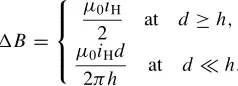
Using a schematic model of an auroral electrojet driven by field-aligned currents at its boundaries (Swift, 1981), one can relate the magnitude of a ground magnetic disturbance B to the value of a field-aligned magnetospheric current. The ground magnetic disturbance is produced by a band of Hall current with surface densityiHand widthd located at altitudehabove the ground is as follows
B=
⎧ ⎪ ⎨ ⎪ ⎩
μ0iH
2 at d ≥h, μ0iHd
2πh at d h.
(51)
Above a highly-conductive Earth’s crust these values are to be doubled. The ionospheric current is related to the field-aligned current above the ionosphere by the current continuity condition. Taking into account a scale factor
B(m)/B(i)owing to altitude variations of the flux tube cross-section, we obtain an estimate of the magnetospheric field-aligned current density
j(m)= B
(m)
B(i) P H
iH
d (52)
Using 51 for auroral electrojet with d = 10 km, h =
102 km, and
H/P = 10/π, we obtain for altitude
∼2RE(B(m)/B(i)0.1) for a magnetic disturbance 102nT above a highly-conductive crust the estimate of the magne-tospheric current j(m) 7.5×10⁻⁶A/m2. This estimated value is about the critical current magnitude necessary for the excitation of ion-acoustic or ion-cyclotron instabilities in the upper ionosphere (assumingN =103cm−3). 4.3 Estimate of theQ-factor of the MAR with TL
Let us augment the TL model considered in Section 2 above (Fig. 1) by the occurrence of the ionosphere in the plane z = −h1 with Pedersen conductanceIP. Then, at z= −h1we have a boundary condition for Alfven waves
Ex= −(μ0IP)−1By (53)
Re-calculating the impedance from the ionospheric layer (z = −h1+0) to the bottom boundary of TL (z =0−0) we obtain the boundary condition:
Ex= −(μ01)−1By 1=A1 IP−
itank1h1 1−iIPtank1h1
(54) whereIP =IP/A1is the normalized ionospheric con-ductance.
Substitution in (22) instead of the wave conductanceA1 the1 from (54), results in the coefficient of Alfven wave reflection from the combined system TL+ionosphere
R= 1−A3+
⊥2+Sk22h2
G
1+A3+
⊥2−Sk22h2
G (55)
When TL are absent, the relation (55) reduces to the known formula for the coefficient of Alfven wave reflection from the ionosphere (Scholer, 1970; Maltsev, 1977)
RI =
IP−1 IP+1
(56)
Now we use these results for the consideration of a MAR with symmetric thin TLs above the northern and southern ionospheres. Let an Alfven impulse with amplitudeb0 im-pinge on one of the ionospheres, as illustrated in Fig. 7. Upon interaction with this ionosphere a part of impulse en-ergy, T b0, transmits through the ionosphere, and a part, b1 = Rb0, is reflected. After a second interaction with the conjugate ionosphere the relevant parts are R2b
0 and T R2b
0, etc. The resulting damping rate andQ-factor of the MAR with a TL can be estimated as
γ = −2πω ln|R|2 Q= ω
2γ = − π
2 ln|R| (57)
whereRis determined by (55).
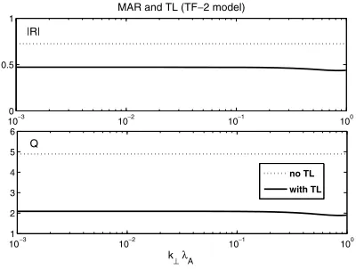
Figure 8 shows a comparison of the results of numer-ical calculations of the coefficient of reflection from the ionosphere (dashed line) and from the TL +ionosphere system (solid line). The chosen parameters of TL corre-spond to TF-2 model,IP =5.0 Ohm−1,VA =103km/s, h1 = 1600 km, N = 109 m−3,ω = 2π/100 s−1. Under these parametersλA0.5 km.
Fig. 7. Schematic illustration of the Alfven wave interaction with a TL+ionosphere system.
Fig. 8. Results of numerical modeling of the MAR with a TL: (a) coefficient of reflection from the ionosphere (dashed line) and from a TL+ionosphere system (solid line); (b)Q-factor of the MAR without a TL (dashed line) and with a TL (solid line).
quality Q are shown in Fig. 8. The reflection coefficient of Alfven field line oscillations between conjugate iono-spheres drops from∼0.7 to ∼0.5 (Fig. 8(a)). The plot in Fig. 8(b) shows that the Q-factor of the MAR even with a thin TL (solid line) is more than 2 times less than without it (dotted line):∼5 and∼2. Upon growth ofk⊥the Q-factor decreases until a minimal value is reached atk⊥∼λ−A1, and then increases under further growth ofk⊥thanks to high re-flection of small scale waves (this interval is of no interest for further consideration and is not shown in the figure).
Transverse scales of typical Pi2 pulsations as observed on the ground are much larger thanλA. Therefore, damping of these oscillations is determined by the large-scale limit of dissipation on transverse resistance (49). Small-scale disturbances which may accompany Pi2 bursts are expected to be absorbed by the TL.
Thus, the occurrence of a TL with anomalous conduc-tivity indeed results in a substantial increase of the Pi2 damping rate. However, the damping mechanism is differ-ent from the mechanisms proposed in earlier studies, and caused not by a field-aligned, but by transverse, anomalous resistance.
4.3.1 Decay of quasi-static field-aligned currents Turbulence can result not only in additional absorption of
Alfven waves, but it can cause the divergence of quasi-static field-aligned currents. This effect destroys the electromag-netic coupling between the magnetosphere and ionosphere at small scales. From (16) it is possible to estimate the char-acteristic scale of current decrease due to divergence caused by static conductivity in a turbulent medium
za⊥σ0/σP (58)
This relationship indicates that small-scale currents with a transverse scalea⊥ will be totally screened by a TL with thicknessh> z. For example, for TF-2 model parameters (σ0 = 2.9 ×10⁻¹ and σP = 1.9 × 10⁻⁶), a TL with thickness∼103 km causes substantial attenuation of field-aligned current structure with transverse scale<2.5 km.
5.
Discussion and Conclusion
Satellite observations have confirmed that densities of currents transported by Alfven waves in the magnetosphere are sufficient for excitation of anomalous resistance and auroral form activation (Pilipenkoet al., 1999; Rankinet al., 1999; Keilinget al., 2002; Streltsov and Lotko, 2003).
Earlier theoretical estimates of plane Alfven wave damp-ing (e.g., Liperovsky and Martjanov, 1973) were made un-der the assumption that anomalous resistance is evenly dis-tributed along a flux tube. However, satellite observations show that turbulence is concentrated in a narrow layer above the auroral ionosphere (Fejer and Kelley, 1980). Alfven waves impinging on a TL with anomalous resistivity can partially reflect from it, be absorbed, and be transmitted through it. Considerations made in this paper extend the results of earlier works by Lysak and Dum (1983), and Trakhtenhertz and Feldstein (1985). When field-aligned re-sistivity dominates the relative effectiveness of these pro-cesses strongly depends on the wave transverse scale. A TL totally screens small-scale disturbances, and only weakly absorbs large-scale disturbances.
wave interaction with a layer is the Alfven resistive scale λA. It is necessary to mention that the mechanisms of the influence on Alfven waves from the non-resistive potential drop (Vogt and Haerendel, 1998; Fedorovet al., 2001) and from the anomalous resistivity, considered in this paper, are physically different. However, from the mathematical point of view, the reflection from the combined ionosphere-AAR system is formally very similar to those from the ionosphere-TL system with field-aligned resistivity. Surely, transverse conductivity does not occur in the AAR models, but it is of primary importance for the TL model considered here.
The analytical results obtained here may be applied to the description of the Alfven wave interaction either with a thin TL, when the field-aligned wave scale L is much larger than the TL width, L h (Section 2.4), or in the local approximation, when L h (Section 2.1). In the intermediate case, when L ∼h, the model developed cannot be directly applied and a field-aligned dependence of the wave field and TL parameters is to be considered, which could be done only numerically.
Comparison of energy losses estimated from simplified analytical relationships for a thin layer, and numerically calculated from complete formulas for a finite width layer, has shown that the thin layer approximation gives reason-able estimates for all transverse wave scales, except very small. Estimation of the effective damping scale in a turbu-lent cusp shows that the cusp proper cannot be a conduit of Pc1-2 wave energy from the magnetosheath to the ground. This model also shows that the occurrence of anomalous transverse resistance when magnetospheric current exceeds the threshold necessary for the excitation of high-frequency plasma turbulence provides an additional non-linear damp-ing rate of transient Pi2 pulsations.
At the auroral latitudes the convective plasma flow in the presence of a feedback between the magnetospheric distur-bances and distortions of the ionospheric conductance can result in the instability of such system (Pokhotelovet al., 2001; Lysak and Yoshikawa, 2006). In such situation a TL plays an important role providing an electron acceler-ation by anomalous E. The necessary coupling between the magnetosphere and ionosphere for the feedback insta-bility is performed by small-scale Alfven waves. How-ever, the occurrence of TL providing an additional wave absorption and damping at small transverse sales (namely, atL⊥≤λA) can decouple the magnetospheric disturbances from the ionosphere. This effect, though it can influence significantly the development of feedback instability, has not been taken into account yet in the auroral physics.
Acknowledgments. This research is supported by NSF grant ATM-0305483 to Augsburg College (VAP, MJE) and INTAS grant 05-1000008-7978 (ENF). Stimulating discussions with V. Vovchenko and S. Shalimov, and comments of A. Yoshikawa and another reviewer are appreciated.
References
Barsukov, V. M. and M. I. Pudovkin, Field-aligned conductivity and pul-sation parameters,Geomagn. Aeronomy,10, 569–570, 1970.
Dyrud, L. P., M. J. Engebretson, J. L. Posch, W. J. Hughes, H. Fukunishi, R. L. Arnoldy, P. T. Newell, and R. B. Horne, Ground observations and possible source regions of two types of Pc1-2 micropulsations at very
high latitudes,J. Geophys. Res.,102, 27011–27028, 1997.
Engebretson, M. J., T. G. Onsager, D. E. Rowland, R. E. Denton, J. L. Posch, C. T. Russell, P. J. Chi, R. L. Arnoldy, B. J. Anderson, and H. Fukunishi, On the source of Pc1-2 waves in the plasma mantle,J. Geophys. Res.,110, A06201, doi:10.1029/2004JA010515, 2005. Erlandson, R. E., L. J. Zanetti, and T. A. Potemra, Observations of
elec-tromagnetic ion cyclotron waves and hot plasma in the polar cusp, Geo-phys. Res. Lett.,15, 421–424, 1988.
Fedorov, E., V. Pilipenko, and M. J. Engebretson, ULF wave damping in the auroral acceleration region,J. Geophys. Res.,106, 6203–6212, 2001. Fedorov, E., V. Pilipenko, and V. V. Vovchenko, Interaction of Alfven waves with a resistive layer,Geomagn. Aeronomy,47, 606–615, 2007. Fejer, B. G. and M. C. Kelley, Ionospheric irregularities,Rev. Geophys.
Space Phys.,18, 401, 1980.
Fredricks, R. W., F. L. Scarf, and C. T. Russell, Field-aligned currents, plasma waves, and anomalous resistivity in the disturbed polar cusp,J. Geophys. Res.,78, 2133–2141, 1973.
Galeev, A. A. and R. Z. Sagdeev, Nonlinear plasma theory, inReviews of Plasma Physics, edited by M. A. Leontovich,N7, 3–145, 1973. Gudkova, V. A., L. M. Zeleny, and V. A. Liperovsky, About dynamics of
field-aligned currents in the magnetosphere,Geomagn. Aeronomy,13, 318–324, 1973.
Gudkova, V. A., V. M. Barsukov, L. M. Zeleny, A. V. Volosevich, G. A. Loginov, and V. A. Liperovsky, Turbulence in the magnetospheric plasma and damping of Pi2 variations,Geomagn. Aeronomy,14, 764– 766, 1974.
Hudson, M. K., R. L. Lysak, and F. S. Moser, Magnetic field-aligned potential drops due to electrostatic ion-cyclotron turbulence,Geophys. Res. Lett.,5, 143–146, 1978.
Ionson, J. A., Anomalous resistivity from electrostatic ion cyclotron turbu-lence,Phys. Lett.,58A, 105–107, 1976.
Keiling, A., J. R. Wygant, C. Cattell, W. Peria, G. Parks, M. Temerin, F. S. Mozer, C. T. Russell, and C. A. Kletzing, Correlation of Alfven wave Poynting flux in the plasma sheet at 4–7REwith ionospheric electron energy flux,J. Geophys. Res.,107, 1132, doi:10.1029/2001JA900140, 2002.
Kindel, J. M. and C. F. Kennel, Topside current instabilities,J. Geophys. Res.,76, 3055–3078, 1971.
Le, G., X. Blanco-Cano, C. T. Russell, X.-W. Zhou, F. Mozer, K. J. Trat-tner, S. A. Fuselier, and B. J. Anderson, Electromagnetic ion cyclotron waves in the high altitude cusp: Polar observations,J. Geophys. Res., 106, 19067–19080, 2001.
Liperovsky, V. A. and S. A. Martjanov, About damping of hydromagnetic waves in a turbulent plasma,Geomagn. Aeronomy,13, 311–317, 1973. Liperovsky, V. A. and M. I. Pudovkin, Anomalous resistivity and double
layers in magnetospheric plasma, Moscow, Nauka, p. 181, 1983 (in Russian).
Lotko, W., B. U. ¨O. Sonnerup, and R. L. Lysak, Nonsteady boundary layer flow including ionospheric drag and parallel electric fields,J. Geophys. Res.,92, 8635, 1987.
Lyons, L. R., Generation of large-scale regions of auroral currents, electric potentials, and precipitation by the divergence of the convection electric field,J. Geophys. Res.,85, 17–24, 1980.
Lysak, L. R. and C. W. Carlson, Effect of microscopic turbulence on magnetosphere-ionosphere coupling,Geophys. Res. Lett.,8, 269–272, 1981.
Lysak, R. L. and C. T. Dum, Dynamics of magnetosphere-ionosphere coupling including turbulent transport,J. Geophys. Res.,88, 365–380, 1983.
Lysak, R. L. and A. Yoshikawa, Resonant cavities and waveguides in the ionosphere and atmosphere, inMagnetospheric ULF Waves: Synthesis and New Directions,Geophys. Monogr. Ser., edited by K. Takahashi, P. J. Chi, R. E. Denton, and R. L. Lysak,169, 289–306, AGU, Washington, D.C., 2006.
Maltsev, Yu. P., Boundary conditions for Alfven waves on the ionosphere,
Geomagn. Aeronomy,17, 1008–1011, 1977.
Mazur, N., E. Fedorov, V. Pilipenko, and A. Leonovich, Interaction of Alfven front with the plasma anomalous resistance layer,J. Plasma Phys.,73, 241–256, 2007.
Pilipenko, V., S. Shalimov, E. Fedorov, M. Engebretson, and W. Hughes, Coupling between field-aligned current impulses and Pi1 noise bursts,
J. Geophys. Res.,104, 17419–17430, 1999.
Pokhotelov, O. A., V. Khruschev, M. Parrot, S. Senchenkov, and V. P. Pavlenko, Ionospheric Alfven resonator revisited: Feedback instability,
J. Geophys. Res.,106, 25813–25824, 2001.
nonlinear dispersive field line resonances,Geophys. Res. Lett.,26, 663– 666, 1999.
Senatorov, V. A., Solution of the wave Alfven equation with account for finite conductivity and viscosity,Geomagn. Aeronomy,36, 164–165, 1996.
Shalimov, S. L. and V. A. Liperovsky, About saturation of turbulent energy density in field-aligned currents,Space Res.,26, 247–255, 1988. Scholer, M., On the motion of artificial ion clouds in the magnetosphere,
Planet. Space Sci.,18, 977, 1970.
Streltsov, A. V. and W. Lotko, Reflection and absorption of Alfvenic power in the low-altitude magnetosphere,J. Geophys. Res.,108, 8016, doi:10.1029/2002JA009425, 2003.
Swift, D. W., Mechanism for auroral precipitation: A review,Rev. Geo-phys. Space Phys.,19, 185–212, 1981.
Tikhonchuk, V. T. and V. Y. Bychenkov, Effect of anomalous resistivity on
MHD wave damping,J. Geophys. Res.,100, 9535–9538, 1995. Trakhtengertz, V. Yu. and A. Ya. Feldstein, About dissipation of Alfven
waves in the layer with anomalous resistance,Geomagn. Aeronomy,25, 334–336, 1985.
Vogt, J., Alfven wave coupling in the auroral current circuit,Surv. Geo-phys.,23, 335–377, 2002.
Vogt, J. and G. Haerendel, Reflection and transmission of Alfven waves at the auroral acceleration region,Geophys. Res. Lett.,25, 277, 1998. Yagova, N., V. Pilipenko, E. Fedorov, M. Vellante, and K. Yumoto,
In-fluence of ionospheric conductivity on mid-latitude Pc3-4 pulsations,
Earth Planets Space,51, 129–138, 1999.